


Important Links
Product Page
Store Page
Assembly Instructions
Bill of Materials
Schematic
Capacitor and Resistor Lookup Guide
Welcome to the 4093 NAND Synth Assembly Instructions – let’s get started!
BOM Layout

NAND Synth Kit
The first step in any successful electronics project is to make sure that you have all of the parts necessary to complete the circuit.
Check your kit against the BOM. If you are missing a part, we’ll send it to you free of charge.
Attention: Changes may occur after the Assembly Instructions are created and the photos may not reflect those changes. Always use the BOM to verify the placement of components.
PCB-Mounted Components

Begin by locating the component identifiers for R1, R2, R3, R4, and R5. Insert the resistors and solder all components onto the PCB.

Next solder the IC socket to the PCB and insert the 4093 IC, aligning the notch in the socket/IC with the corresponding marking on the silkscreen.

Our next step will be to insert all capacitors through the PCB and solder into place. Align the stripe/shorter lead on the the 2.2μF and 100μF capacitors with the negative via on the silkscreen. The 0.1μF capacitors are not polarized and may be inserted in any orientation.
Wired Components
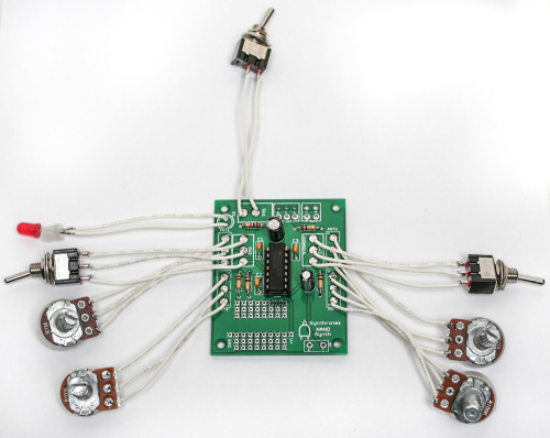
The next major step in our project assembly will be the wired components. Attach wires to all of the potentiometers, switches, and jacks beforehand. This will save time and the construction of the circuit will be much simpler.
Solder the leads connected to the leftmost and rightmost contacts on the potentiometers to terminals 1 and 3, respectively. See the photo below for reference orientation:

When installing the pot, some pots come with nubs near the shaft that may get in the way of installing the circuit into a case. Check for a nub and clip as necessary.

Don’t forget to cut the nubs on the potentiometers as necessary.
Next solder the leads running from the SPDT and SPST switches to the appropriate terminals on the PCB.

Attach wire leads to the LED, optionally inserting the plastic LED mount of the legs of the LED prior to soldering. Solder the LED leads to the terminals on the PCB – connect the wire running from the leg closest to the flat edge of the LED to the corresponding contact as indicated on the silkscreen.
Proceed to solder the leads running from the output jack to the ‘T’ and ‘S’ contacts on the PCB – see the photo below for reference:
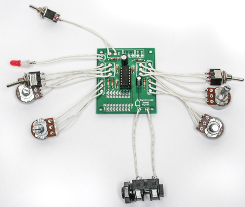
See the following photo if you are installing an 1/8″ jack:
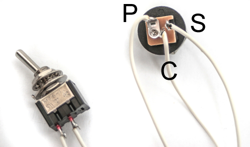
Next insert the wire leads connected to the DC jack through the strain relief holes in the PCB and solder into place.
The P, C, and S terminals on the PCB correspond to the following contacts on the DC jack:
Optional: install the 9v battery clip by inserting the leads through the strain relief holes – connect the red lead to the positive (+) contact and the black lead to the negative (-) contact. If you do not want to install the 9V DC jack and only install the 9V battery clip, short the S and C pins for the 9V DC Jack as shown in the photo below:
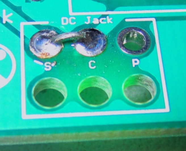
Short these contacts to get the circuit to work without the 9V DC Jack
Completed Project
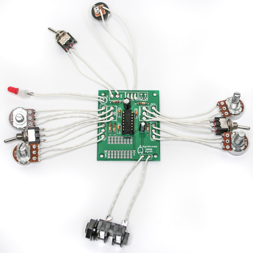
Congratulations, your NAND Synth circuit is complete! Connect your circuit to a power source and amplifier to test if it’s operational. If not, go back through the steps in these instructions and look for any mistakes. When you have a fully functional circuit, check out the mods section below for ways to modify your circuit. Have fun with your hand-made NAND Synth!
Mods
CV Input
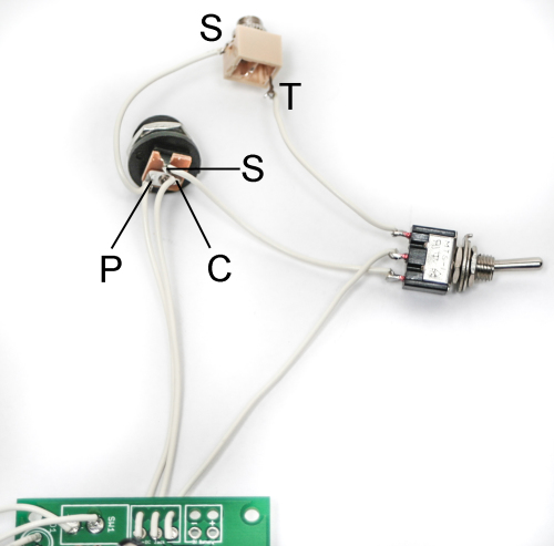
This mod allows you to use an external control voltage signal to alter the NAND Synth’s output pitch. The additional mono jack, SPDT switch, and wire necessary to perform this mod are included in all retail kits and specified in the BOM. Begin by building up the NAND according to the instructions, but omit the DC jack.
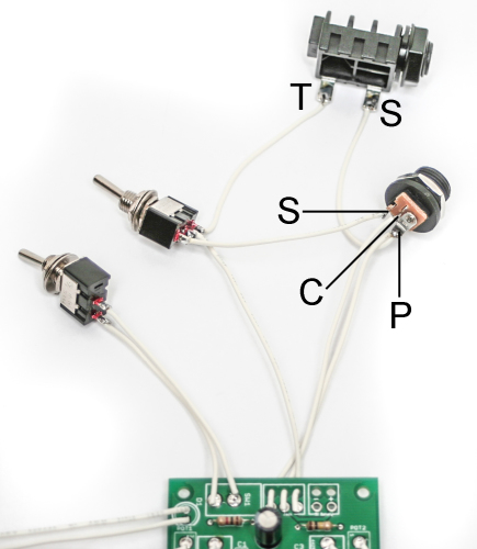
Solder wire between the tip contact of the mono jack jack and one of the two outer solder lugs on the SPDT switch. Connect the other outer lug to the ‘S’ contact on the DC jack, and the middle lug to the ‘S’ contact on the PCB. Solder wire leads from the mono jack sleeve contact and ‘P’ contact on the PCB to the ‘P’ contact on the PCB. Finally, connect a wired lead from the ‘C’ contact on the DC jack to the ‘C’ contact on the PCB.
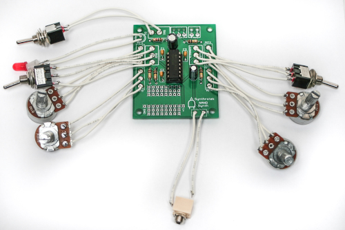
The DC jack, additional mono jack, and SPDT switch should be wired similarly to this reference photo:
See the following photo if you are using an 1/8″ jack:
Alright, you’re finished! Now go grab your sequencer and start making some noise!
Dive Bomb
This mod allows you to momentarily cut the power off to the circuit, resulting in an an awesome-sounding Dive Bomb effect. It’s a simple mod and only requires a SPDT switch and some wire. For maximum playability, we suggest using a momentary pushbutton SPDT switch.
These instructions use the 9V battery source for these instructions. If you choose to use this mod with both jacks, you will need a separate pushbutton switch for each power source. Because of the PCB layout, this mod is only able to be used with one power source.
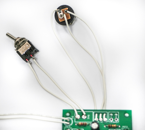
Locate the red wire of the 9V Battery Jack, clip it halfway down the length of the wire, and strip the ends (if you are using the DC Jack instead, cut the wire connected to the DC Jack through-hole labeled ‘S’).
Attach two long wires to the stripped leads and solder.
Next, find the COM (common) and N.C. (normally closed) connections on the switch. Connect the newly-attached wires from the 9V battery adapter to these solder lug positions on the switch (it does not matter where each goes).
That’s all there is to it! Now your NAND Synth circuit is capable of Dive Bombing like a guitarist!
Note: The length of the Dive Bomb can also be shortened or lengthened depending on the capacitor value used. More on this coming soon!
What capacitor do I change to change the dive bomb length?
awesome litte project that works well i just got the pcb boards as i had lots of parts that were order by mistake so decided to order the boards on ebay were here like here in 9 days and i am in the uk so this was a great service from the start other boards too Atari Punk Console ,Arbiter Fuzz Face Clone ,8 Step Sequencer facebook page http://www.facebook.com/home.php#!/analogsynthprojects
I am having a hard time getting the nand to respond to CV input.
I am using a Midi to CV converter as found here:
http://www.acxsynth.com/midi2cv/midi2cvfr.htm
it puts out 4 voices (1v per octave range) and 4 gates/triggers, along with a Din24 time sync.
any information about the CV input of this thing (voltage, polarity, etc) would be appreciated.
Hi Jeremy, sorry for the delay, I lost an employee and it looks like the comments were not regularly updated. As for the Nand Synth, there is not really a specific voltage to note spec. The Nand is rather powered by the CV in lieu of the DC power, so there has to be a switch to bypass the the 9V DC to the CV input. It sounds neat and you can tune it in to make fun noise, but making a specific note by some standard will not work. Please email us at synthroteksales@gmail.com for any future support requests. I am trying to catch up on the comments. Sorry again
Hi I’m ordering components for my chaos nand board and was wondering if the SPDT switches were on-on switches. Also can’t find a potentiometer that is called a 100 Kohms Audio,could only find linear or logarithmic.
Can you help?
Thanks,Paul
Hi, the SPDT switches are On/On switches. And for the pot, Audio pots are logarithmic pots. We just call them audio because for volume control you need logarithmic pots for a linear control of the volume.
Hi. The BOM specifies 3 x SPDT switches & 1 x SPST, but the board and the assembly instructions only show three switches in total – am I missing something?
Hello John,
If you scroll down on the Assembly Instructions you’ll notice a MOD section. The extra SPDT is for that mod. Hope that helps!
Hi just wondering if you can use a midi to cv converter and trigger the nand with PC midi sequencer software? Thanks,Paul
How can I make the CV in mod function on the chaos NAND work with only useing the 9 V battery “only” configuration. I really hope to make this synth work on battery power only. Thanks.
Hi Paul, did we never get back to you on this? At any rate, any CV should work
Micky, it is helpful to have the DC Jack switch in the circuit to help keep the battery isolated from incoming CV voltage. Can you wire it up as shown in the instructions, but just not use the DC jack for power?
Hi there, is this PCB through hole or surface mount? I love your guys kits they rule! ! !
It’s through-hole. Thanks for the love!
I finished building my Chaos NAND module but I have found that the volume on this module is far lower than that of the APC as well as the optical theremin (both of which I have built myself). Is there any solution that you know of that may help increase volume output?
Hey Craig,
I know if you use the CV input on the NAND, the volume level is going to be dependent on the input level, and how hot it is.
I’m going to bring back the first question from Marc. Which cap should you replace to lengthen the dive bomb time? I’m guessing C6 but I’d like to be sure about it. Will be ordering a bunch of PCB’s soon.
Yes, i’m pretty sure it would be C6, though we haven’t messed with it in house, yet. A larger cap would take longer to discharge.
Thanks.
I can confirm that c6 is indeed the cap you swap.
How do you recommend wiring up the cv function if I’m only powering using dc jack wired to battery + and – ?
Hey There,
I would start by wiring the tip of the jack to one of the outside legs of your SPDT switch. Then solder the Sleeve connection to the – connection of the DC Jack, or any other ground connection. Next, solder the + from the DC jack to the other outside pin of the SPDT switch. Now solder the middle pin of the SPDT to the + spot on the PCB. The Final step is to solder the – on the DC jack to the – spot on the PCB. Soldered this way, you can either take power from the DC jack or the CV Jack, depending on which way you have the switch set.
Best regards,
-Patrick at Synthrotek
Thanks for the hints on how to wire the cv input mod. I forgot how to wire up and LED on the older revision of this 4093 synth.
Can I add extra LED’s to the board? If so, how? Thanks
Hey Newwy,
If you’re looking to add more LEDs to D1 on the board, then it should be a simple process. Adding more LEDs in parallel like that will the split up the current going through each LED, causing them to be less bright. So I would suggest also changing out R5 to a lower value to allow more current to run through the LEDs to ground. Changing R5 will control how bright or dark the LED is. Blue and green draw more current than red LEDs so that is also something to consider.
Have fun!
-Zach
@Steve Harmon
Cheers Zach, I will look into that. I’m bit of a noob but have done a couple of small, basic electronic kits, including a basic Atari Punk buster drone…lol.
This NAND looks fun. I wanted to get a nice enclosure and put a few extra LED’s on it…just to bling it up a bit…ha.
Would I use a junction box to add the extra wires to D1?
Thanks again for your advice.
What can you do with the +v and gnd area. I got it all assembled just fine just curious what else I can do with it.
Hello,
The empty solder pads are for modding, there’s nothing specific for them, they just break out the power and ground so you are able to mess with the circuit if you want to.
Best,
-Patrick at Synthrotek
Hey hey. I’m currently building this and having a blast. Any chance that there is some information on what size to drill the pilot holes for the switches and jacks? Keep up the great work.
Cheers!
Good evening! I have a question regarding volume. I purchased both the Astro noise and 4093 quad nand pcb’s, have them assembled and both are working great. My only problem is the output volume is too low. I know it’s not my amplifier (I built it from scratch, puts out plenty of sound). What can I do to up the output volume?? The problem is especially prevalent on the 4093 quad nand. I’ve already tried lowering the pot value attached to the volume, it helped a little bit. Thank you!
I’m response to my own question and another above mine, there is a fantastic way to increase the output volume, on the volume pot 4 use a 10k pot instead, and in R4 I found a 2.2k resistor puts out the audio power I was looking for.
Your instructions do not include which pots go where. After spending an afternoon trying to put this together, i now have a tone generator with a functioning on/off, one pot that controls pitch, and a few extra pots and switches that do nothing but kill audio.
Hey Travis,
I think you might have become a little too excited to get your NAND going and missed the very first step, as the very beginning of these instructions we have directions to verify placement with the BOM, which is a link at the top of this page. Assembly instructions are there to make sure you get the proper order of things, but in DIY world, the Bill of Materials is always your best friend.
Feel free to shoot us an e-mail with photos of the top and bottom of your build to store@synthrotek.com and we’ll try and get you sorted and jamming!
-Michael
Hi, can’t get this to work. All I get is a high pitched whine, which is only altered by the volume control. No other controls have any effect. I have checked it against your BOM and instructions. Could it be the IC is defective? Any help would be appreciated. Thanks, Robert Shave
Hey Robert,
Haven’t seen a defective 4093 since getting into electronics, so I’d be more inclined to suspect solder joint quality since you’ve already verified all parts and orientation against the documentation. If you’d like to send some photos of the top, bottom, and wiring of your project to store@synthrotek.com, I’d be happy to give it a look and do some annotations on anything suspicious.
Thanks,
Michael
HI Michael, I found I had caused a short and I think it had damaged the IC. Sorted it and put a new IC in and its fine now. One other little problem at the moment is when connecting to a sequencer, I only get a tone which I cannot change. Any ideas? Thanks again Robert