


This product has been discontinued.
Important Links
Assembly Instructions
Bill of Materials
Schematic
Capacitor and Resistor Lookup Guide
LoFi Audio Amplifier Assembly Instructions
Welcome to the LoFi Audio Amplifier Assembly Instructions! This build is fairly simple and straightforward, so let’s get started!
BOM Layout

The first step in any successful electronics project is to make sure that you have all of the parts to construct the circuit. Check your kit parts against the BOM Listed Above
If you’re missing anything, we’ll send it to you free of charge
Alright, now that we have everything we need, let’s get started assembling the LoFi Amplifier circuit.
PCB Components
IC/Resistor
 Orient the PCB so that it matches the picture above. Insert the IC into the PCB at the IC1 position. You may have to gently squeeze the leads of the IC inward in order to get it to fit onto the PCB. Be careful!
There is only one resistor for this circuit Insert it into the PCB and solder both the IC and resistor to the PCB.
Capacitors

There are five capacitors for this circuit. C1 and C2 are 10μF non-polar ceramic capacitors. You do not have to worry about which lead goes into which hole with non-polar components. If you want to use polarized electrolytic capacitors (like C5) in your circuit, take care to identify the positive lead and insert it into the square through-hole with a a’+’ next to it.
C3 is a 0.1μF ceramic capacitor and C4 is a 0.05μF ceramic capacitor. Just like C1 and C2, you don’t have to worry about polarity with these components. Just place them into their through-holes and the circuit will work fine.
C5 is a fairly large 220μF electrolytic capacitor. Take note of the black band on C5 in the picture above. The lead that is closest to this band is the negative lead. If the capacitor is new, the longer lead will be the positive lead. On the PCB, insert the positive lead into the square through-hole marked with a ‘+’. Insert the negative lead into the circle through-hole.
That’s all of the on-board components. We’re halfway done!
Wired Components
Volume Potentiometer/9V Battery Jack

We’ll start with the 9V battery jack. Insert the red wire into the PCB through-hole marked ‘+’ and the black wire into the through-hole marked ‘-‘. That’s it.
The volume potentiometer is a little bit more involved.

On the PCB, the silkscreen identifier for POT1 has numbers near the outer through-holes. These correspond to the potentiometer’s solder lugs.

When you are attaching the potentiometer to the PCB, make sure the right wires go to the right through-holes based off the above picture.
DC Jack

The DC jack, when wired properly, allows you to keep a 9V battery connected to your circuit while only using the power from a wall wart. Your battery will not be drained, which is a good thing considering how expensive 9V batteries can be. When you unplug from the DC Jack, the 9V battery will kick into action and power the circuit.
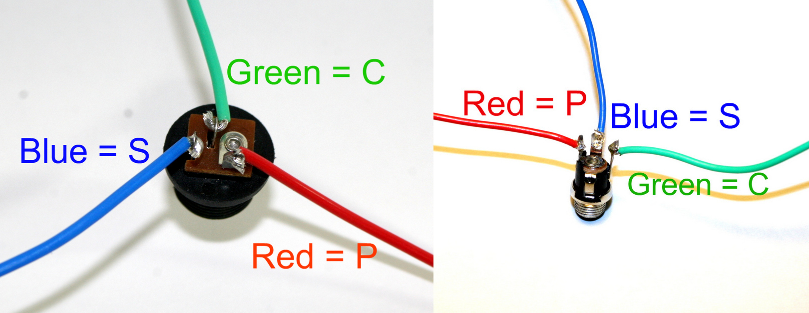
DC Jack Pinout
Solder three wires to the DC Jack’s solder lugs and connect them to the PCB at their corresponding ‘DC Jack’ through-holes.
If you do not want to install the 9V DC jack and only install the 9V battery clip you will have to short the S and C pins for the 9V DC Jack like shown in the picture below*.
* Your PCB may not look exactly like the photo, that is ok. What is important is that you short the same pins as shown in the photo.
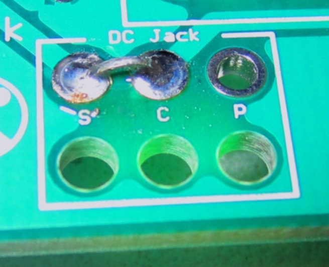
Short these contacts to get the circuit to work without the 9V DC Jack
Audio Jack/Speaker

One of the best features about this LoFi Amplifier is that it will not draw power unless something is plugged into the input. We accomplish this by using a stereo jack. When you insert a mono plug into the stereo jack, the circuit is completed and the signal will be amplified.
If you are not familiar with stereo jacks, here’s a picture to help you identify the connections:

There is a solder lug under the top connection. This will not be used in the circuit.
On the PCB at the ‘IN’ connection, there are three letters that correspond to the stereo jack connections: ‘T’ for Tip, ‘R’ for Ring, and ‘S’ for sleeve. Connect the stereo jack to the PCB with wire.
The last component to be added to our circuit is the 8Ω speaker. At the ‘OUT’ PCB position, there are two through-holes. Connect one wire from a solder lug on the speaker to the PCB and repeat for the other. It does not matter which hole goes where, as speakers aren’t polar components.
Congratulations, you’ve finished building the LoFi Amplifier circuit!
Speakers ARE polar components! We called it “phase” in sound. If you connect your speaker the wrong way it will sound out of phase. It means that it will depress his membrane instead of moving it forward… Although not so dramatic with this kind of speaker! 😉
Quite right
so i purchased this kit not to long ago, never got it to work and now i’m trying to diagnose what’s the problem. my kit included all polar capacitors except for C3 and C4, those are inserted the proper polarity but when i plug in the kit i just get this horrible loud tone, then if i turn the pot it gets really crunchy but doesn’t control the volume. do i have a deffective kit?
I have a continuous tone omitting from my speaker whenever anything is plugged into the input. It sounds like the Atari Punk unit sounds. I reversed the speaker wires to see if that was the issue but it is not. Any advice? Everything seems to be correct and in top shape.
I am working on this right now for you guys, should have an answer tomorrow. Any photos?
unfortunately I do not own a camera :\ I could work on it, but I do not know how soon I could get that to you. My capacitors I received were kind of hard to differentiate (aside from the c5). I got 3 blue and 1 Yellow. 2 of them had long leads and 2 had short.
You can check your capacitor values here:
http://www.synthrotek.com/wp-content/uploads/2012/08/Capacitor-Codes.pdf
Using the chart, it looks like I had two of them in the wrong holes. I think I ended up destroying the board while trying to switch them out with some desoldering damage control :\ so frustrating. I guess I’ll have to order a new kit when I get the money.
Andy! and others… the caps may be wrong, BUT I think I got a bad batch of LM386 Ic’s… still checking…more to come. I will replace anyones kits or IC’s (if your kit is in good order). Just email us, but give me until the middle of next week to figure it out.