


Important Links
Product Page
Store Page
Assembly Instructions
Bill of Materials
Schematic
Capacitor and Resistor Lookup Guide
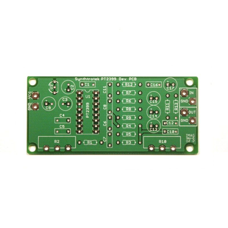 PT2399 Dev Delay PCB |
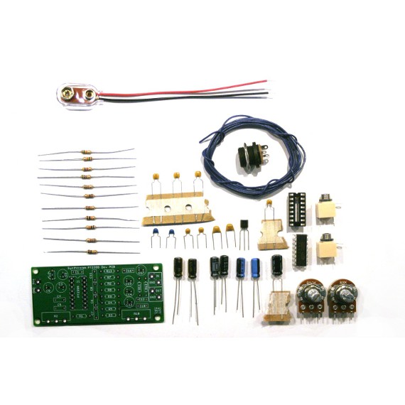 PT2399 Dev Delay Kit |
The PT2399 Delay Dev Kit is a great way to get started experimenting with the PT2399 Echo Processor IC!
Features:
- Based off of Princeton’s PT2399 Echo Application Circuit (straight off the datasheet), this PCB gives you the exact set-up recommended by the manufacturer. Engineers and hobbyists alike can use this basic design to modify it for their own purposes The PT2399 Echo Processor IC is a very versatile circuit with adjustable input/output filtering, delay length, wet/dry mix, and a lot of unexplored potential!
- On-board 5V regulator allows for multiple powering options and interfacing with digital circuits. Use a 9V battery, 9-18V AC Adapter, or connect it to your a DC central power supply (such as Eurorack ribbon cable power supplies).
- 2 potentiometer placement positions adhere to the datasheet schematic, allowing for direct control over how much delay is present in the output signal. Delay length is variable from fast slapback echo to long dub-style repeats to noisy long repeat madness! Mix allows you to set the wet/dry portions of the signal.
- The PT2399 Echo IC was designed to mimic old-school analog BBD delay with modern digital sampling technology. Repeats degrade at higher delay lengths. Shorter “echoes” result in a very natural well-filtered reproduction of your synth/guitar tone.
- PCBs are designed here at Synthrotek. PCB silkscreen, through-hole components with careful on-board placement, and wire-tension relief holes were designed with the DIYer in mind!
- PCB Dimensions: 3.125″ x 1.375″
- Great for synths and guitars! Easy to configure and mod your circuit for a greater delay range, delay length modulation, and a lot more!
Check it out in action:
where can I find schematics for the mod shown on the 3rd video? the one with the yamaha nand. thanks!
Hello,
we don’t have any schematics on that mod, but the assembly instructions page has the how to on getting the feedback mod.
Best regards,
-Patrick
Hi. What is the max delay time?
Hi, Andy
The PT2399 chip has a range of ~30ms – 1.13 seconds. Beyond that time, the sample rate reduces for some pretty neat glitchy effects.
-Michael
What would daisy chaining a couple of these things together sound like?
Never tried it, but it would probably be pretty cool!
I am having problems with your boards not wanting to take solder. I’ve bought the 4093 board, the APC x2, 2 of the dev delay boards, the passive ring modulator, the optical theramin and a cosmic echo. I have cleaned them with alcohol, and I’ve even tried steal wool. Used more than plenty of flux and have had problems with all of them taking solder. It’s not every pad.
I’m not new at soldering as I’ve had jlcpcb make some boards for me and haven’t had any problems with them.
Am I missing something?
I recommend using a soldering iron with a base station if you aren’t already, that does help. Adafruit has a great soldering guide too, check it out here:
https://learn.adafruit.com/adafruit-guide-excellent-soldering?view=all
I have a soldering station. I have become quite proficient with it. If all of the pads on the boards weren’t accepting solder, I would blame my skill but it’s maybe 2 or 3 pads on each of them that refuse to take solder. As I said, I have cleaned them and I have tried several different temperature settings, different types of solder, different types of fluxes, different ways of cleaning and I have read different techniques of troubleshooting. I have done everything possible to get these things to take solder. I don’t have problems with boards from any where else that I have purchased from. I’m at wit’s end, because I have several boards that I can’t finish because of 1 or 2 pads won’t take solder.
They might be pads connected to the ground plane, which makes them more difficult, especially if they have been worked on a bit. It can help to heat up the boards a little bit before soldering them. Also, clip the lead that you are trying to solder, leaving a little bit to connect with the iron. While soldering it in place, gently scrape the tip of the iron back and forth a bit. Let me know if that works!