


Important Links
Product Page
Store Page
Assembly Instructions
Bill of Materials
Schematic
Capacitor and Resistor Lookup Guide
Welcome to Synthrotek Passive A/B Switch Assembly Instructions!
This step-by-step guide will take you through the whole circuit-building process.
Component Layout
The first step in any successful DIY electronics project is to make sure that you have all of the parts and know their reference ID for proper board placement. Check the contents of your kit against the BOM before you begin. If you’re missing anything, send us an email and we’ll get it out to you ASAP.

Components
Assembly
Attention: Changes may occur after the Assembly Instructions are created and the photos may not reflect those changes. Always use the BOM to verify the placement of components.
Resistors

Resistors w/ PCB
You’ll need a 1k resistor for R1, and a 1M resistor for R2, R3, and R4
LED’s

Wiring LED’s
If your planning on using bezels make sure to slide the plastic LED cup over the leads before soldering. Next, bend the leads into small loops, push the wire through, and solder. It helps to make hooks with your wire and twist it around the leads.

LED Placement
The flat side of the LED is negative and the rounded side is positive. Make sure to match up the flat side of the LED with the flat side of the diagram on the board. Also, if you use electrical tape around the wires as shown in the picture: First slide it between both wires, then wrap it around. Take caution to keep the negative and positive leads seperate.
Input and Output Jacks

Audio Jacks
Wire the jacks exactly as they are shown in the picture… : )
Power Supplies

9v Adapter and Battery Clip
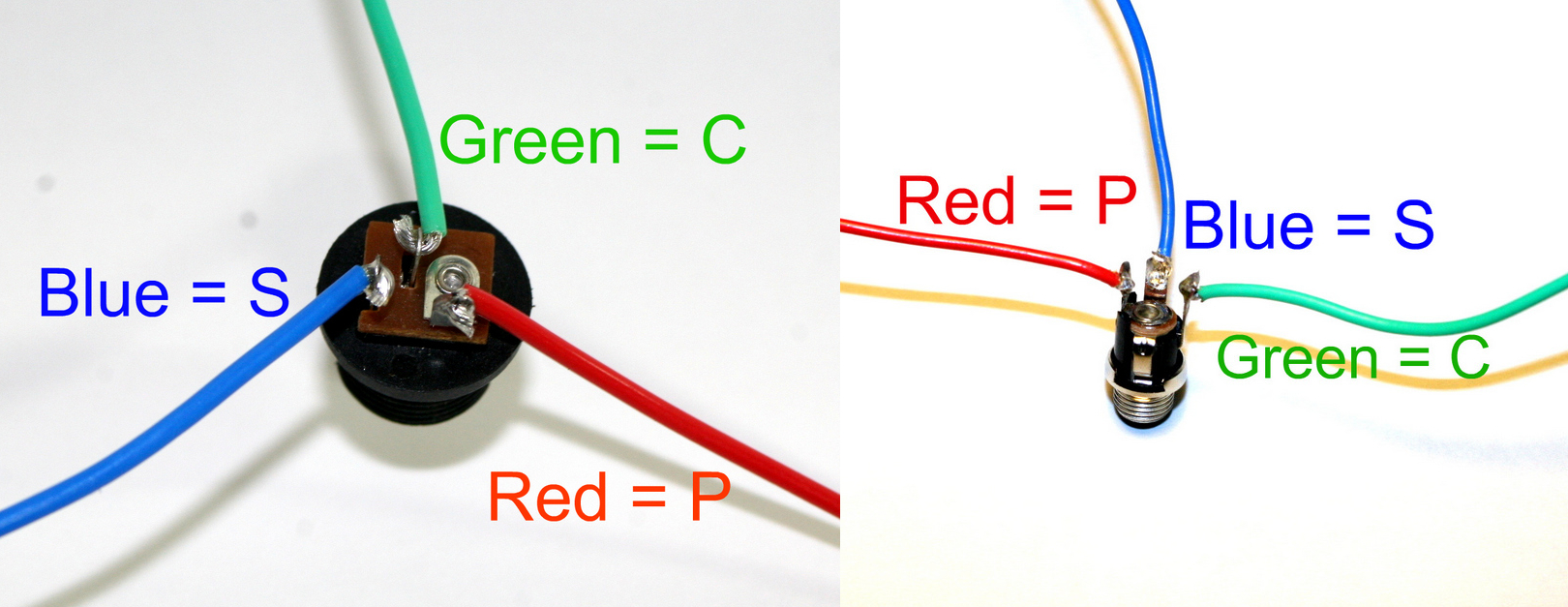
DC Jack Pinout
Again, use the picture as a reference. The fat solder lug on the DC jack is the pin. Match it up with P on the board. The small solder lug in the middle is the (c) connect and the small solder lug on the side is the (s) sleeve.
If you do not want to install the 9V DC jack and only install the 9V battery clip you will have to short the S and C pins for the 9V DC Jack like shown in the picture below*.
* Your PCB may not look exactly like the photo, that is ok. What is important is that you short the same pins as shown in the photo.
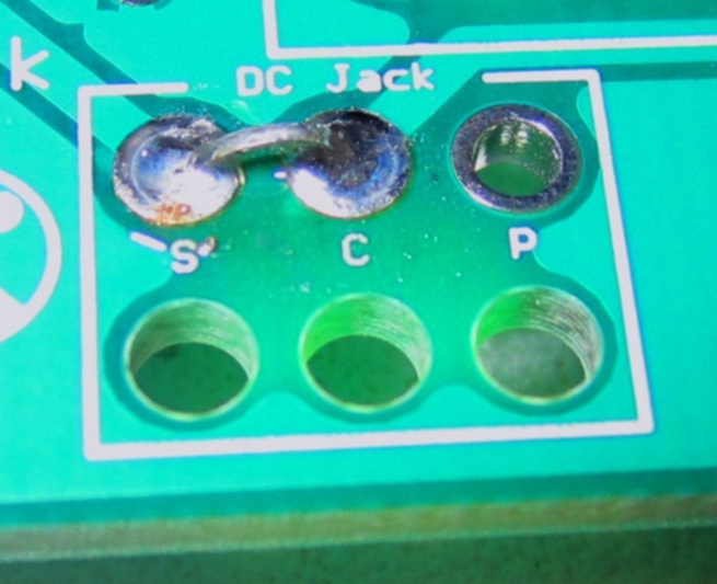
Short these contacts to get the circuit to work without the 9V DC Jack
Stomp Switch

3PDT Stomp Switch

Stomp Switch Wiring
This code will save your life!
Use the picture as a reference to match up the switch to the board. Pay close attention beacuse it’s not fun to redo, unless you love soldering as much as us! In the picture the solid blue side of the switch is facing up.
Finished Circuit!

Complete Passive A/B Switch
NICE!