


Important Links
Store Page
Assembly Instructions
Bill of Materials
Schematic
Capacitor and Resistor Lookup Guide
Optical Theremin Assembly Instructions
Welcome to the Optical Theremin Assembly Instructions! If you’re new to circuit-building, this is a great kit because it’s easy to build and it makes some crazy sounds. Let’s get started!
BOM Layout

Match your kit with this picture to make sure you have all the parts.
If any components are missing, please let us know!
Assembly
Attention: Changes may occur after the Assembly Instructions are created and the photos may not reflect those changes. Always use the BOM to verify the placement of components.
IC Socket, Capacitors, and Resistors

Solder in the IC socket. Line up the half-moon notch with the notch on the PCB.
C1 and C2 are .1uF ceramic capacitors. R2 is a 1M resistor.
Ceramic capacitors and resistors are non-polar so don’t worry about negative or positive leads.
Power Supplies

Black is negative, Red is positive

Wire up the DC jack as shown. P=Pin S=Sleeve C=Connect
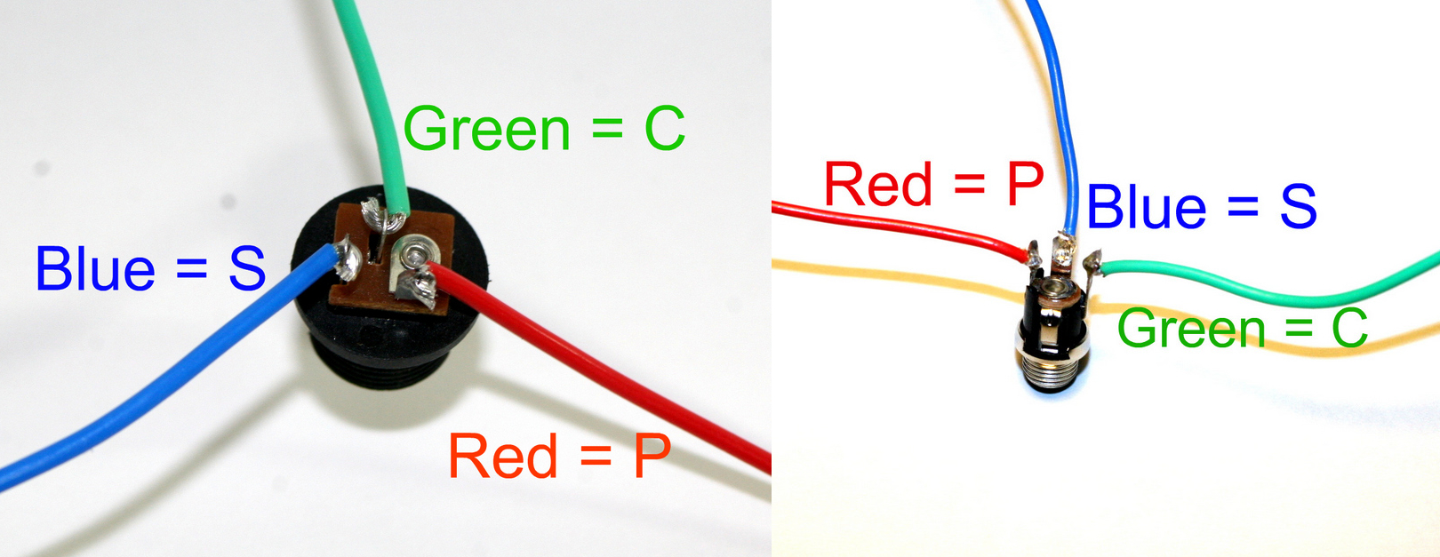
DC Jack Pinout
If you do not want to install the 9V DC jack and only install the 9V battery clip you will have to short the S and C pins for the 9V DC Jack like shown in the picture below*.
* Your PCB may not look exactly like the photo, that is ok. What is important is that you short the same pins as shown in the photo.
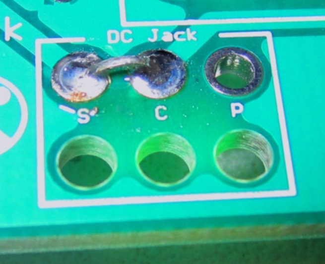
Short these contacts to get the circuit to work without the 9V DC Jack
Potentiometers


Use the pictures above.
The B1k pot will be wired on pins 1 and 2. The B1M pot will be wired on pins 2 and 3.
Don’t worry about the extra pins on the potentiometers.
Wire the pots to the PCB… R4=B1k R5=B1M
When installing the pot, some pots come with nubs near the shaft that may get in the way of installing the circuit into a case. Check for a nub and clip as necessary.

Don’t forget to cut the nubs on the potentiometers as necessary.
On/Off Switch

Wire as shown in the picture above.
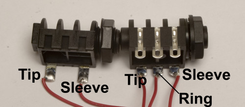
Mono Jack

Wire as shown in the picture above. S=Sleeve (ground) T=Tip
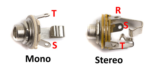
If you are using 1/4″ jacks, please use the diagrams below to wire them in properly.
Optical Resistors

R3 and R1 are the optical resistors. Wire them up in any way you choose!
Complete

Congrats! Note that if you are using an AC adapter, it needs to be 9v center NEGATIVE.
[…] Optical Theremin Assembly Instructions […]
[…] Optical Theremin Assembly Instructions […]
Hi! Getting ready to build this and super stoked. I’m new to electronics and had some questions. I was thinking about putting a DPDT switch at the out put and wiring in a small speaker or buzzer. I was thinking it would be cool for playing when there is no amp or traveling etc. also I was wondering how difficult it would be to add a cv out for use with my atari punk console.
Cheers!
Hello,
The switch speaker idea is a good one, and totally possible. But the circuit has no way of modding a cv output from it, unfortunately.
Best,
-Patrick
Thanks!
@Patrick Kelly
Hello, I’m also completely new to electronics and the instructions say “Short these contacts to get the circuit to work without the 9V DC Jack”. Does this mean that by shorting these contacts I lose the option to use a 9V DC adapter as supply? I’d like to keep both options working (battery and adapter). Thanks.
Hey Lucy,
You are correct, if you short the contacts, you loose the 9v DC jack as a power option. If you are wanting to keep both options, you can just solder both up normally as per the instructions, and you can just use one or the other. Hope this has helped,
-Patrick
What size knobs go on the pots? And (forgive my ignorance), is it possible to wire the Theremin output to the existing output jack on an electric guitar, or will this fry something? Thanks.
Roger,
We use Davies Clone knobs, witha 9mm shaft diameter. I would not recommend wiring any two outputs together, especially without circuitry to protect the two things being hooked together.
Best,
-Patrick
hi, i recently order this I seem to be missing many of the wires? I’m not sure I this is correct or not
also, i’m not sure how I’m supposed to connect the wires to the jacks, the switches, or the potentiometers. Sorry if I’m asking a lot of questions. But this is my first time working with electronics.
Hey Jorge,
If you ordered a kit, we send a small spool of wire (about 5ft) with them, so you would need to cut that into the smaller pieces that are needed. As for the proper wiring, just follow the pictures above, as they show the proper orientation. Also, this bit of text from the instructions says where to solder each pot:
Use the pictures above.
The A100k pot will be wired on pins 1 and 2. The B1M pot will be wired on pins 2 and 3.
Don’t worry about the extra pins on the potentiometers.
Wire the pots to the PCB… R4=A100k R5=B1M
When installing the pot, some pots come with nubs near the shaft that may get in the way of installing the circuit into a case. Check for a nub and clip as necessary.
Best Regards,
-Patrick at Synthrotek
This is my first time doing something like this and I have some questions. I have the 1\4 mono jack so how do I wire that up? What’s the deal with theknobs, are the wires pigtailed then just soldered into the knobs? And then what am I supposed to do with the photo resistor and 555 timer that came with this? Also on my A100k the top wasn’ t fully machined I don’t know if it changes anything I just think it is odd. I learn by doing and seeing so if anyone can explain using pictures or video it would be much appreciated. I have no idea what I am doing
hiya, i am just about to build this and was curious in regards to enclosures…does this need to be in a metal box for shielding &/or grounding purposes? i was recently told that a lot of effects pedals need to be shielded in a metal enclosure to not pick up excess noise from outside. does this apply to any of the synthrotek kits? i could not find any mention in regards to enclosure types. personally i like the idea of using wood enclosures (and even in some cases plastic or cardboard), because it’s a bit easier to drill the holes with the tools i have. also, a slightly unrelated question…can the optical resistors be used with a 4093 circuit?
Hey Polly,
We sell our completed optical theremins (The Evil Eye) in plastic cases. With this build it should make no difference what enclosure you use. A wood case sounds awesome! I’ve always felt pedals should be wooden.
And yes, anywhere you would normally use a variable resistor/potentiometer you could instead use an optical resistor. In fact, you can use it to replace any resistor. But replacing a pot would be the most straightforward.
-Zach
Hey Emmy,
I’m sorry you’re having issues with your optical theremin kit.
Originally, I denied this comment and responded to you through email. We like to use this blog to answer more general questions about our products. When it comes to specific build issues it is more efficient to communicate back and forth through email. However, because your email address is not working I will respond here.
Would you be able to send over a couple pictures of the top and bottom of the board to store@synthrotek.com?
Also include photos of your wired components. There’s a good chance some of your wiring may be incorrect.
The more pictures you send, the better my chances are of figuring out the issue.
Also, the kit should have come with two optical resistors. In your email you mentioned something about having an extra one, but you also stated that didn’t have enough.
If you have another email we could use to communicate that would be great! I’m totally happy to help you out but it would save a lot of time if we were able to respond more directly. Also feel free to give us a call!
Thanks
-Zach
Just built this circuit in a 3X3X3 housing. I used a mini gooseneck(for the pitch sensor) to get better separation and control over the optical resistors, with the volume sensor in the housing. I also used a small blue cap that fits over the pitch sensor that actually extends the range of pitch control if you were to adjust the pitch to its highest level , that way you could have a greater range of pitch from very low to very high. A total blast, I mix the signal with my various stomp boxes to get some ethereal noise!
hi Cheech! i’m very interested about your bending, i’m beginer in electronics (and not so good in english) so i’ve not understud everything. what is a “mini gooseneck”? and witch caind of “blue cap” did you pu on it? like something transparent? mi feeling it that the light sensors have not enought influence to both controls and it will be very nice to do something for this!
I have a small component speaker (1 1/2 inches across; two wires sticking out. Sorry, I don’t know the official name for the part). Can I attach that in place of the 1/4 inch output? the speaker has 8 ohms of resistance and takes 1/2 Watt of power.
You should have an option on your store to buy just the case for this. You have the kit, and the Evil Eye, but not the case separately. Either that, or include the case in the kit. Obviously, I’d really like a case, but I’m out of luck now.
Hey Mary,
Here is a link to the case sold separately:
http://store.synthrotek.com/Serpac_232i_9V_Black_Plastic_Case
You will have to drill your own holes but this is the style of case we use the Evil Eye.
-Zach
Hey Mary,
Go for it! It should work great.
-Zach
@Steve Harmon
Awesome, thanks!
Question: About how long does a battery last in it?
Hi,
So I wired everything up according to instructions and hooked it up to a 9v battery but its making no sound. Do I need to plug it in to a speaker in order to see if it works? If not, how do I trouble shoot what went wrong?
Hi Kimberly, yes you will need a small amp or powered speaker to hear the audio.
Hey guys! Can I replace 1M pot to 500k pot? Thanks!
You can, it will limit the range a bit, but it will work
What type of LDR does this use light or dark? And is a 1meg to much?
Hi Hex, the LDR’s decrease in resistance when they are in contact with more light. The range could be in the Megaohms when dark and in the 100 ohms when in bright light
I just got this kit and I’m excited to build it. Curious about hot surface mount the photresistors though. In the evil eye models I’ve seen online, there appears to be some kind of surface mount casing for them. Is there a part # or a link to something that would work for the ones that come with this kit?
Hi Erik, we used metal LED bezels for that circuit like these:
https://store.synthrotek.com/5mm-LED-Bezel-Metal_p_559.html