Thank you for purchasing the Synthrotek Passive MIX kit! This is pretty easy build, great for first-time DIYers.
Please build according to the BOM, and not these instructions or the pictures alone. Some components may have changed since these were written, or we may not be able to get the proper components in the pictures.
Let’s begin!
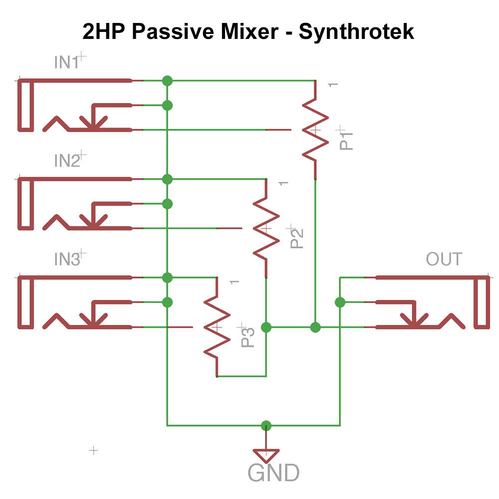
THESE INSTRUCTIONS ARE FOR THE MIX v.2 which has some added resistors. These resistors help reduce the interaction between channels. Both versions have their advantages. If you are looking to build version 1.0, PLEASE FOLLOW THIS LINK.
Mix v2 Instructions
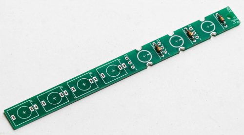
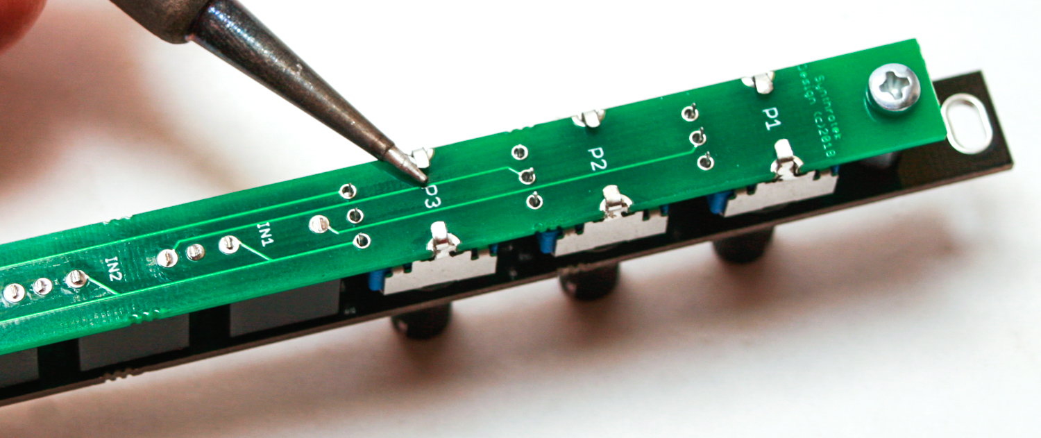
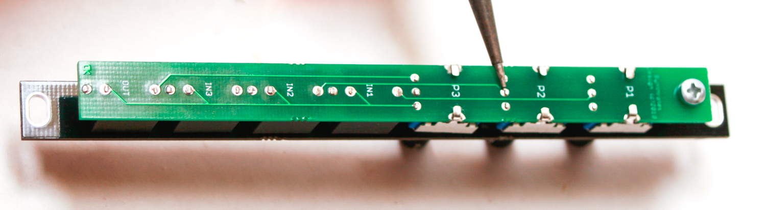
RESISTORS
Take the 3 resistors and place them into the panel as shown below. Resistors are not polarized, so you can place them either way. Turn over to solder then clip excess leads.
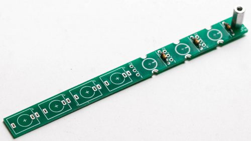
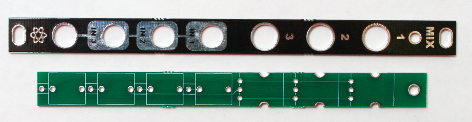
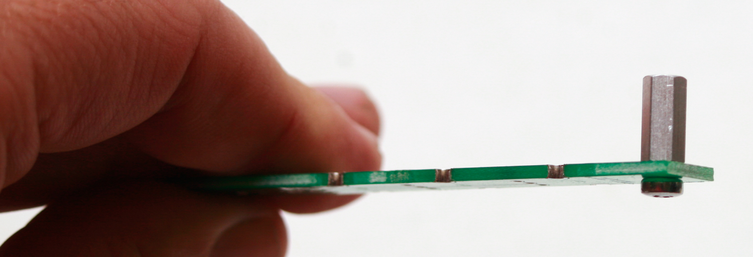
STANDOFF
Take the 10mm standoff and attach it the PCB with the silver 2.5mm screw
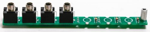
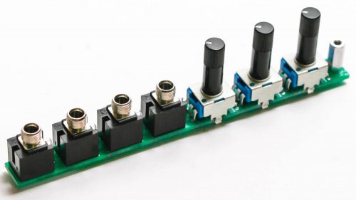
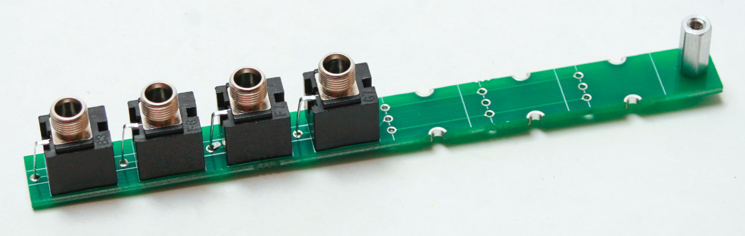
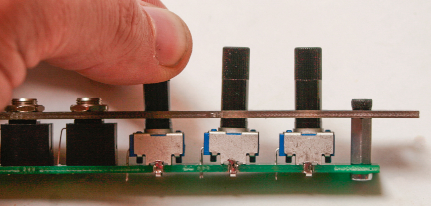
JACKS
Place all of your 3.5mm jacks in the PCB as shown below. Place them on the the side of the board that has the white silk screen boxes. You can use the panel to align the jacks then turn over and solder in place. Wait until final panel placement to solder.
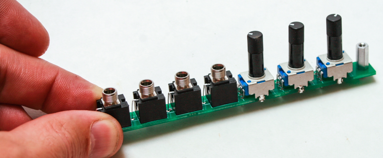
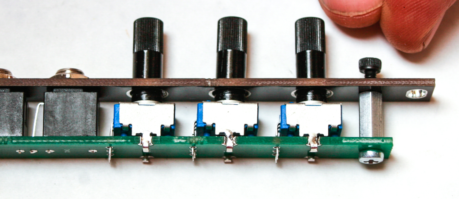
Potentiometers
Take the 3 pots and place them into the PCB. Wait until final panel placement to solder.
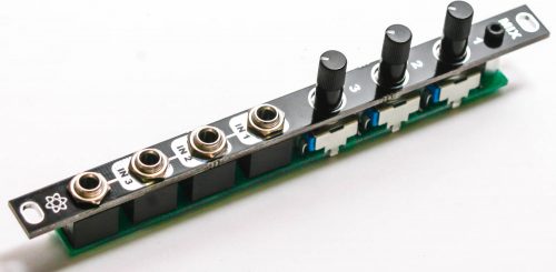
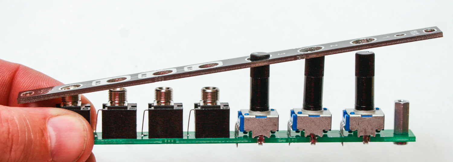
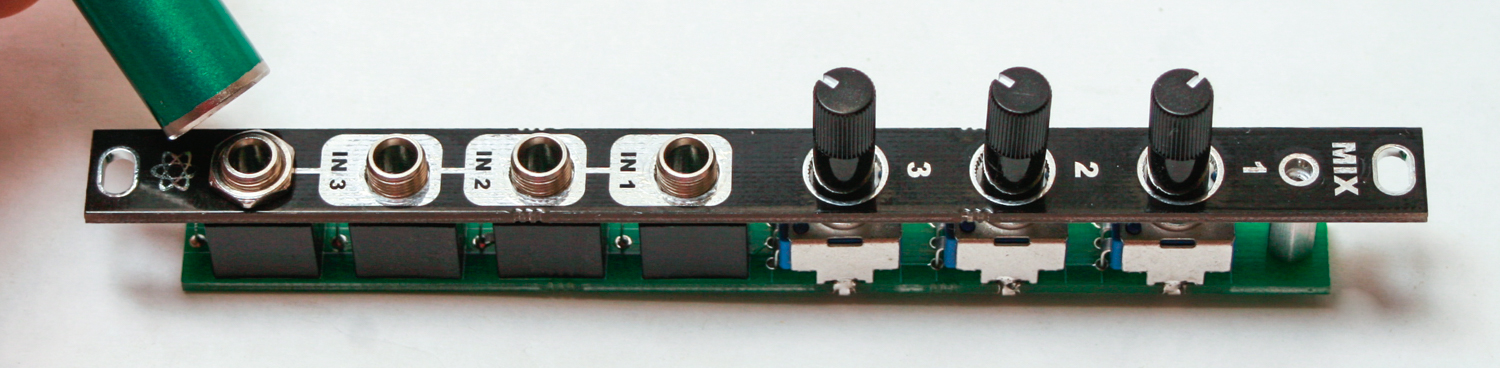
Panel
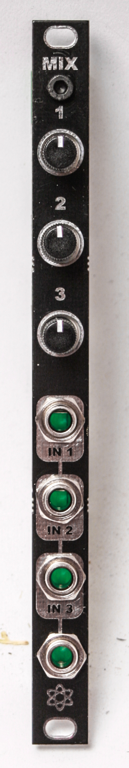
Now take the panel and carefully place it over the pots and jacks. You can add the 2.5mm hex screw to the standoff and hex nuts on the jacks. Carefully turn the project over and solder the pots and jacks in place. You can now test your MIX. Congrats!
MIX v.1 Assembly Instructions
MIX Eurorack Passive Mixer PCB and Panel
Take the 10mm standoff and attach it the PCB with the silver 2.5mm screw
MIX Standoff
Place all of your 3.5mm jacks in the PCB as shown below. Place them on the the side of the board that has the white silk screen boxes. You can use the panel to align the jacks then turn over and solder in place.
MIX – Jacks
Now place the pots onto the PCB as shown below.
MIX-Pot Placement
Then take the panel and place it over the pots and the jacks.
MIX – Panel Alignment
Carefully add the jack nuts.
MIX – Jack Nuts
Tighten down the black hex 2.5mm screw through the panel into the standoff.
MIX – Black 2.5mm Screw
Now squeeze the pot clamps onto the PCB then solder ONLY the pot clamps onto the PCB. DO NOT SOLDER THE PINS YET.
MIX – Pot Clamp Soldering
Align the pots now by hand so that they are vertical and centered.
MIX – Align Pots
Solder pot leads into place once the lots are aligned, then solder the jacks.
MIX – Pot Lead Soldering
Make sure you tighten the nuts on the jacks and you are then good to start mixing!
MIX Final Build