


Skiff Power Mini Assembly Instructions/BOM
Skiff Power Mini Lite Assembly Instructions/BOM
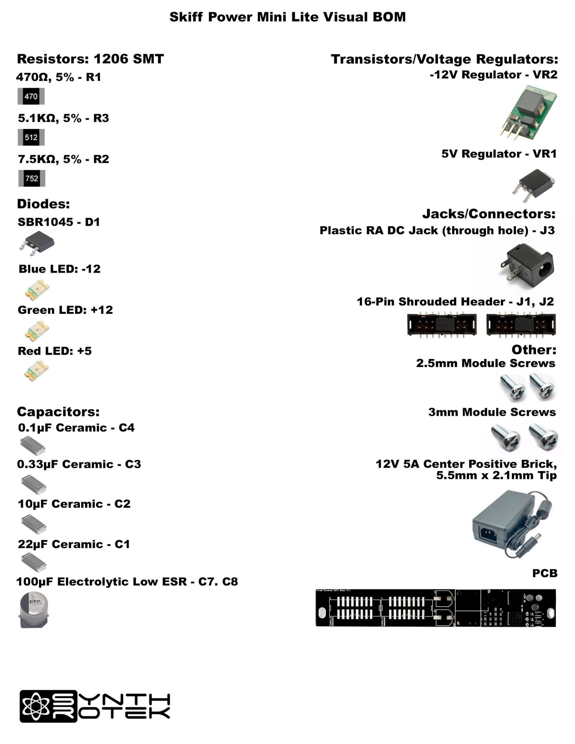
Capacitor and Resistor Lookup Guide
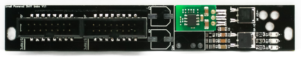
Skiff Power Mini Lite
Thank you for purchasing the Skiff Power Mini Lite! This is an intermediate build. If you feel like you can handle it, please proceed! If not, get some help from a friend with experience or purchase a fully completed unit.
Please build according to the BOM, and not these instructions or the pictures alone. Some components may have changed since these were written, or we may not be able to get the exact components in the pictures.
For a BOM with Mouser part numbers, click here.
General Advice on SMD Soldering
SMD soldering is a different beast compared to through hole soldering. We encourage you to take extra time, and to be careful as you open the bags containing these very small components.
We suggest adding a small amount of solder to one of the pads that you will be working with PRIOR to placing the component. Using a good pair of tweezers, place the component on the pads and carefully reheat the solder on the pad that was tinned. If the placement looks good, then go ahead and solder the component to the pads.
Recommended tools:
- small tweezers
- magnifying glass
- fine soldering tip
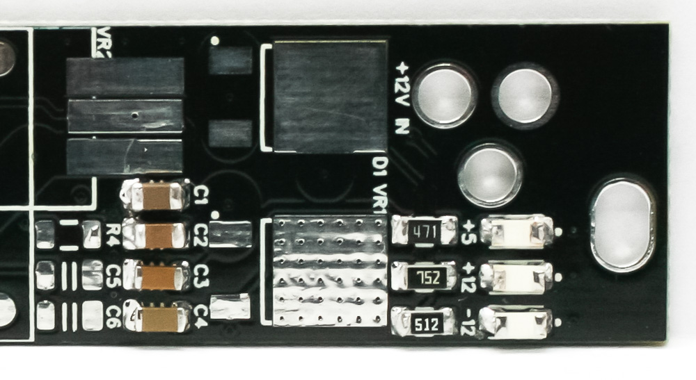
Resistors
Resistors are not polarized and can be placed either direction. Solder these using the same method as the diodes. Add some solder to one of the pads prior to placing the component; a small amount is enough. You can then use tweezers to hold the resistors in place while tacking it down.
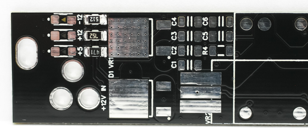
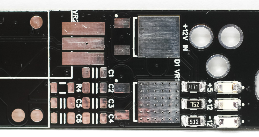
Skiff Power Mini RESISTORS
LEDs
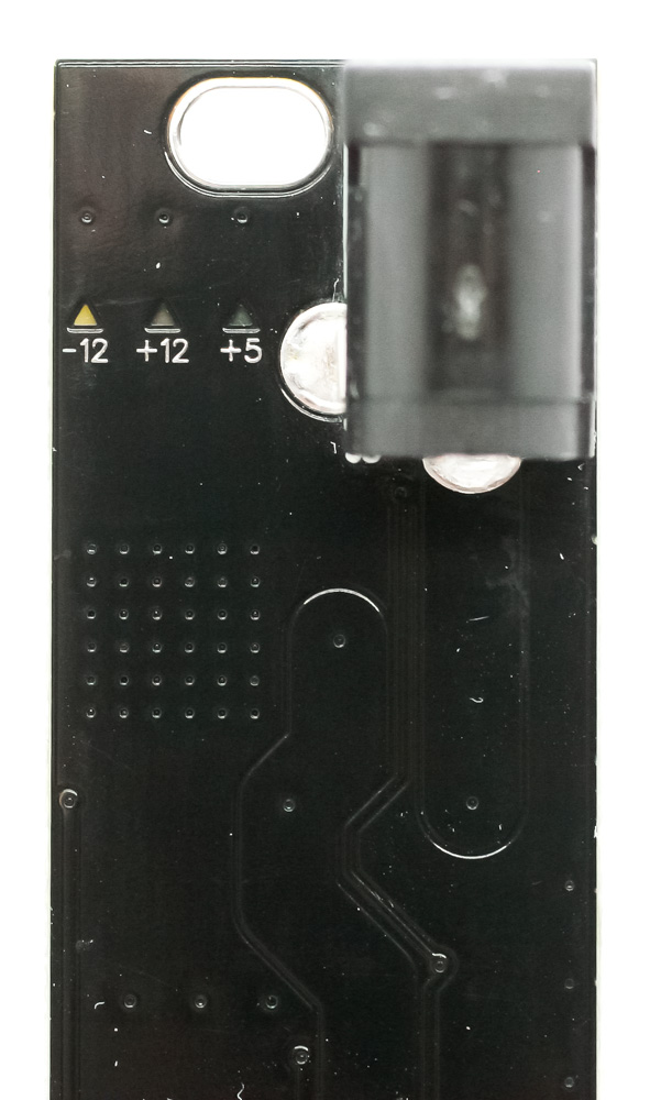
The Skiff Power Mini LEDs need to be placed so that the lens is facing the PCB (as they shine through the PCB). LEDs are polarized and must be placed in the proper direction. The copper pad on the LED that looks smaller or like a large black “C” is the cathode or negative side. This negative side needs to be aligned with the small ‘dot’ on the PCB. Add some solder to one of the pads prior to placing the component; a small amount is enough. You can then use tweezers to hold the LEDs in place while tacking it down.
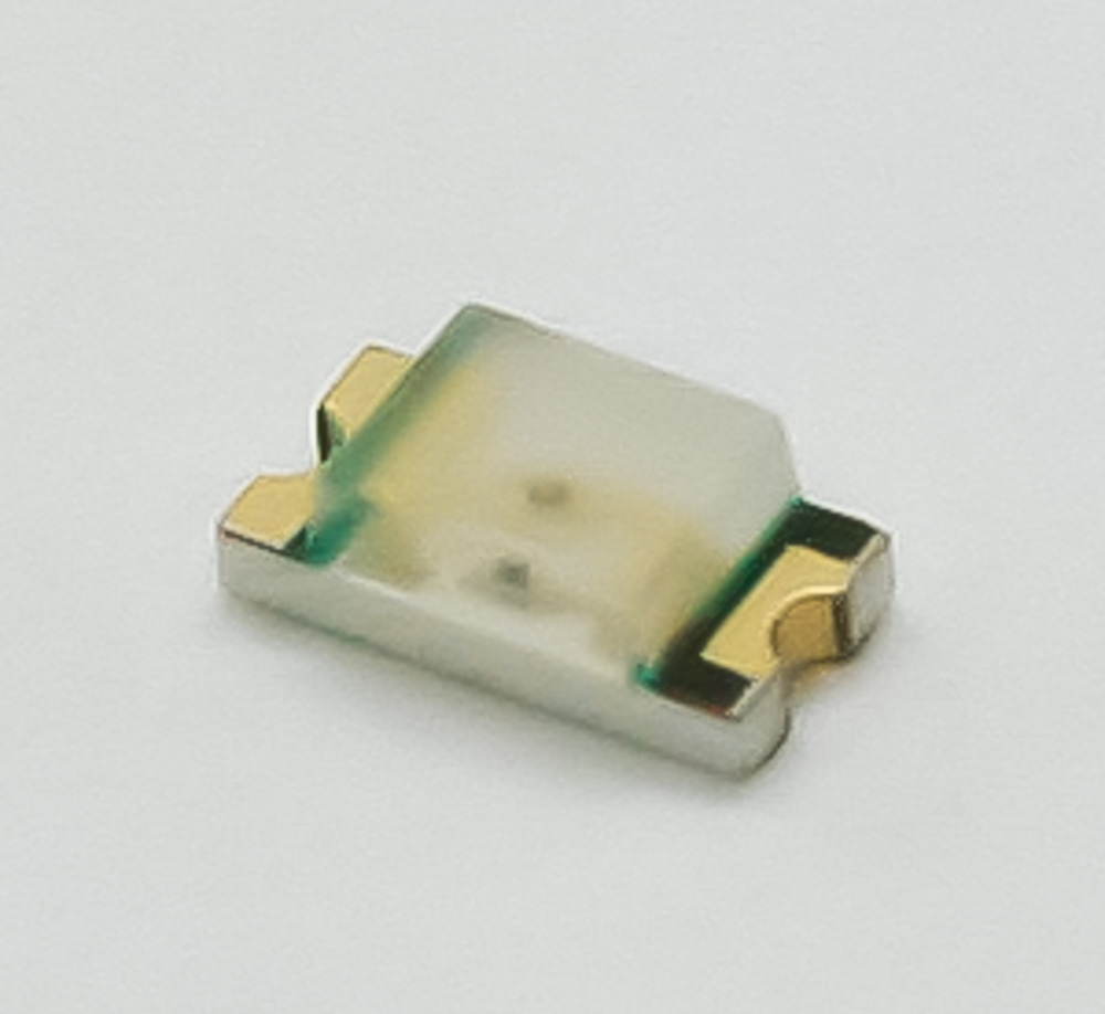
Skiff Power Mini – LEDs
Skiff Power Mini – LEDs
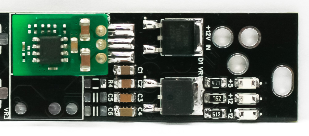
Ceramic Capacitors
The ceramic capacitors are non-polarized, so you can place them in either direction. Add some solder to one of the pads prior to placing the component; a small amount is enough. You can then use tweezers to hold the capacitors in place while tacking it down.
Skiff Power Mini – Ceramic Capacitors
+5 Voltage Regulator & Diode
Add some solder to one of the pads prior to placing the +5V regulator and diode. Tack them down in place. Make sure the upper tab is also soldered to the large pad on the PCB.
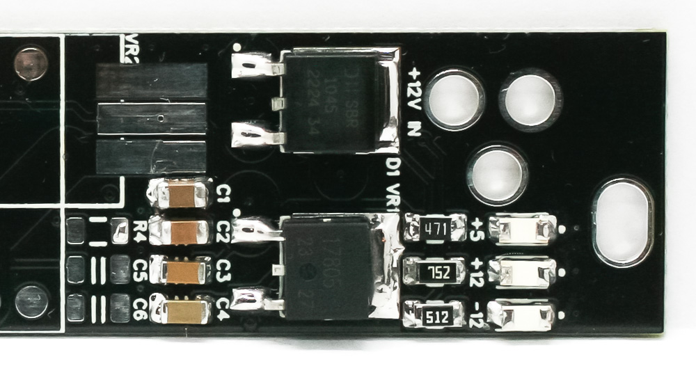
Skiff Power Mini Diode
-12V Regulator
Add some solder to one of the pads prior to placing the -12V regulator. Tack them down in place.
Skiff Power Mini -12V Regulator
Skiff Power Mini -12V Regulator
16-Pin Power Connector
Place the 16-pin power connector into the PCB by aligning the notch on the connector with the notch on the PCB silk screen. You can add a little bit of solder to one of the pads then carefully tack the rest in.
Skiff Power Mini – 16 Pin Power Connectors
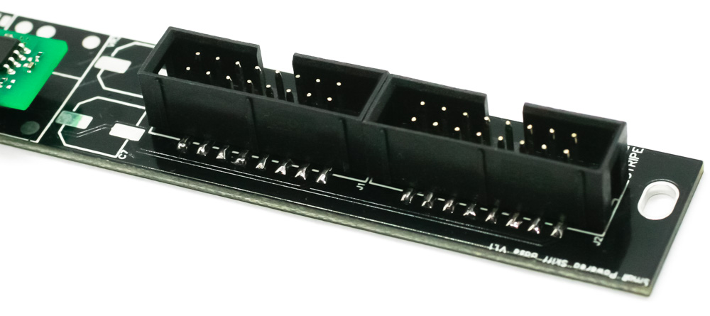
Skiff Power Mini Connectors 2
Electrolytic Capacitors
Electrolytic caps are polarized, so place the caps as shown below by aligning the caps with the footprint on the silkscreen. Add some solder to one of the pads prior to placing other side in.
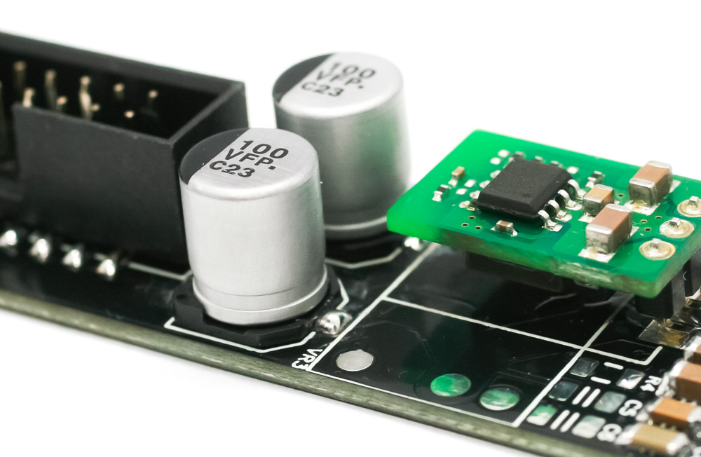
Skiff Power Electrolytic Capacitors
DC Power Jack
Place the DC jack into the PCB as shown below, turn over to solder in place. Congrats! You are done with the build.
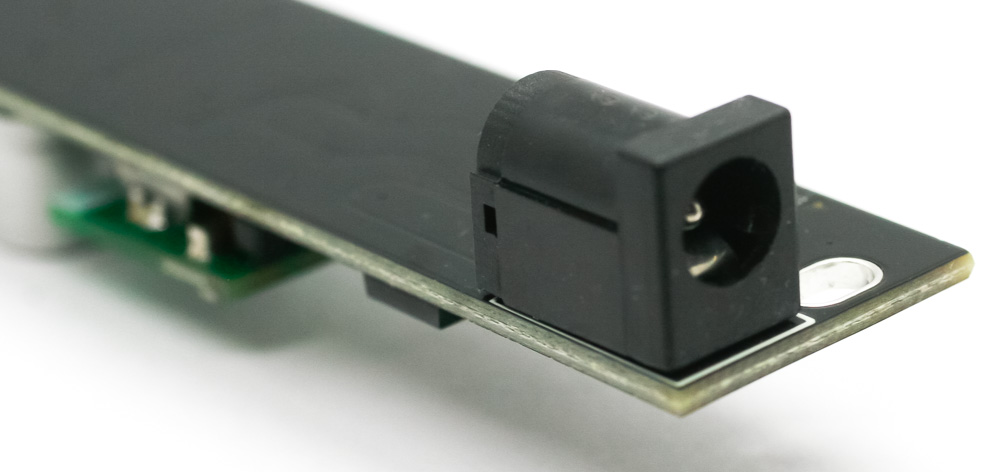
Skiff Power Mini DC Jack
Skiff Power DC Jack 2