


Important Links
Product Page
Store Page
Assembly Instructions
Bill of Materials
Capacitor and Resistor Lookup Guide
Thank you for purchasing the Synthrotek Ribbon Controller Touch Interface Kit! While this is an easy build, it is very important to get all the components properly soldered into the PCB in the correct placement. If you feel like you can handle it, please proceed! If not, get some help from a friend with experience or purchase a fully completed unit.
These assembly instructions have two sections, one for the 1U version, and one for the 3U version. The 1U version instructions is shown with the 44HP board, but the steps are identical for the 24HP version as well.
Click Here for the 1U Version | Click Here for the 3U Version | Click Here for the Riblet
Please build according to the BOM, and not these instructions or the pictures alone. Some components may have changed since these were written, or we may not be able to get the proper components in the pictures.
Lets Begin!
1U Ribbon Controller Touch Interface Assembly Instructions
Jacks
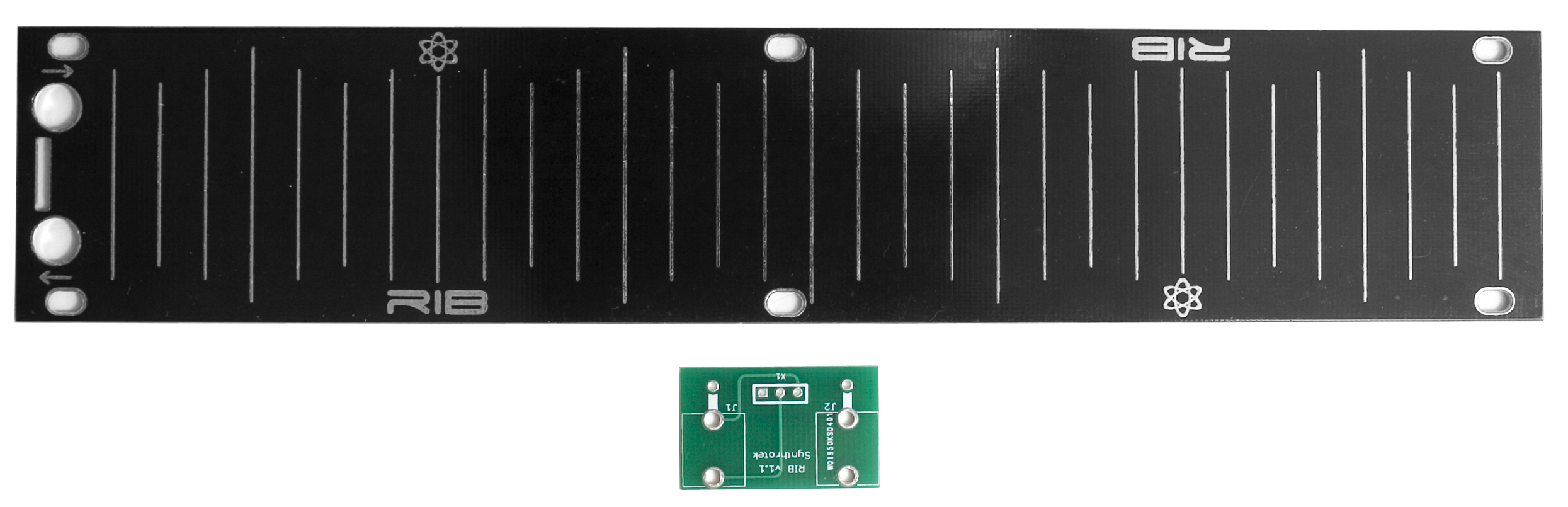
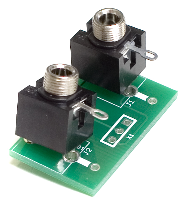
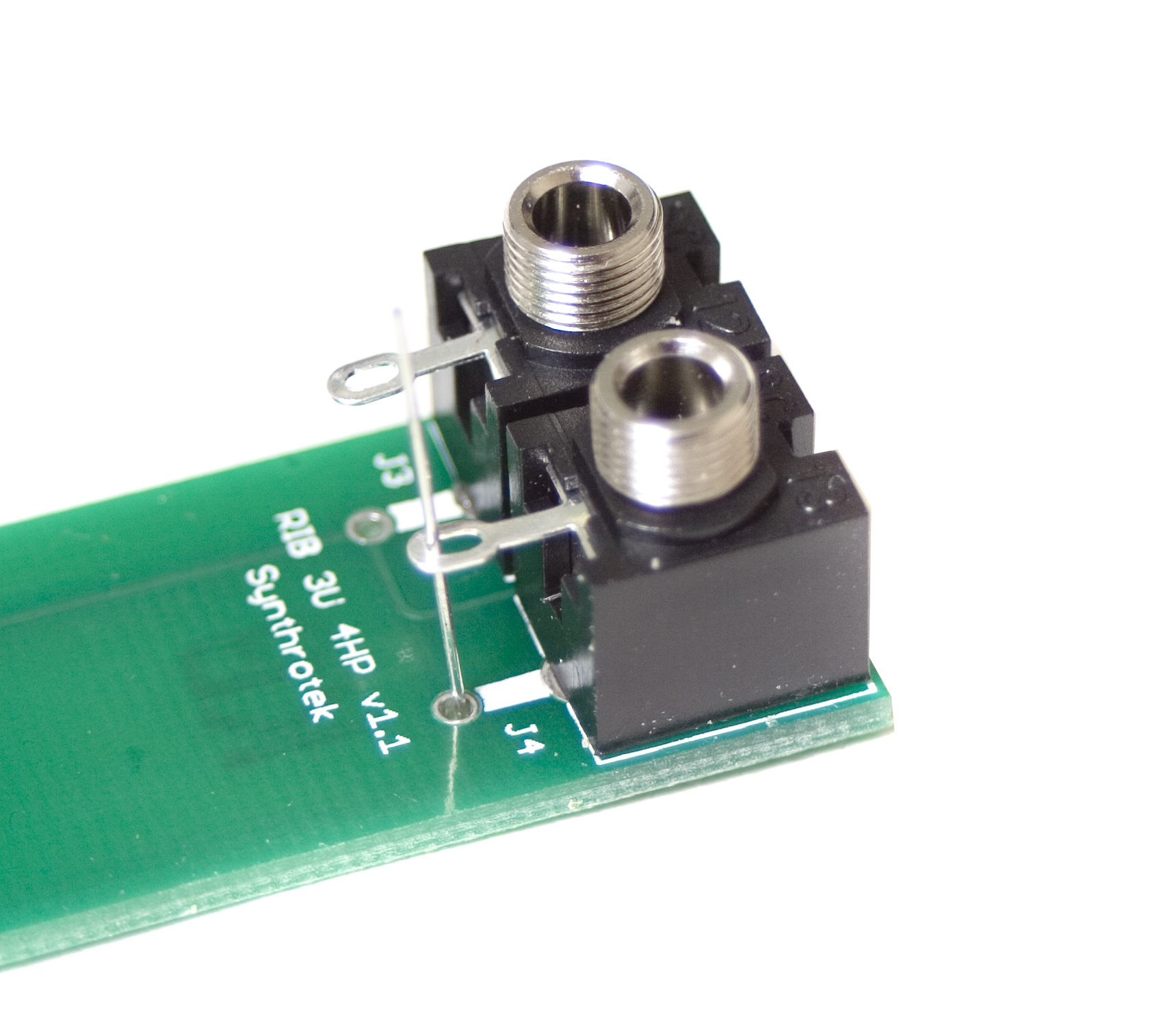
First up, we are going to put the two TRS jacks in the board. Insert them through the PCB in the proper spots, as shown below. Don’t solder them in yet, as we need to make sure they align with the panel properly.
*Due to manufacturing tolerances, if you have v1.1 of the PCB, you may need to trim one of the legs of the jack for it to fit into the board.
First Assembly
Next, fit the panel over the two jacks, and hand tighten the nuts on the top of the panel. You can then twist the jacks slightly so they are aligned straight with the panel and PCB.
 Then, using a tool, tighten the nuts down so the jacks can’t move around any more.
 PCB Alignment and Soldering
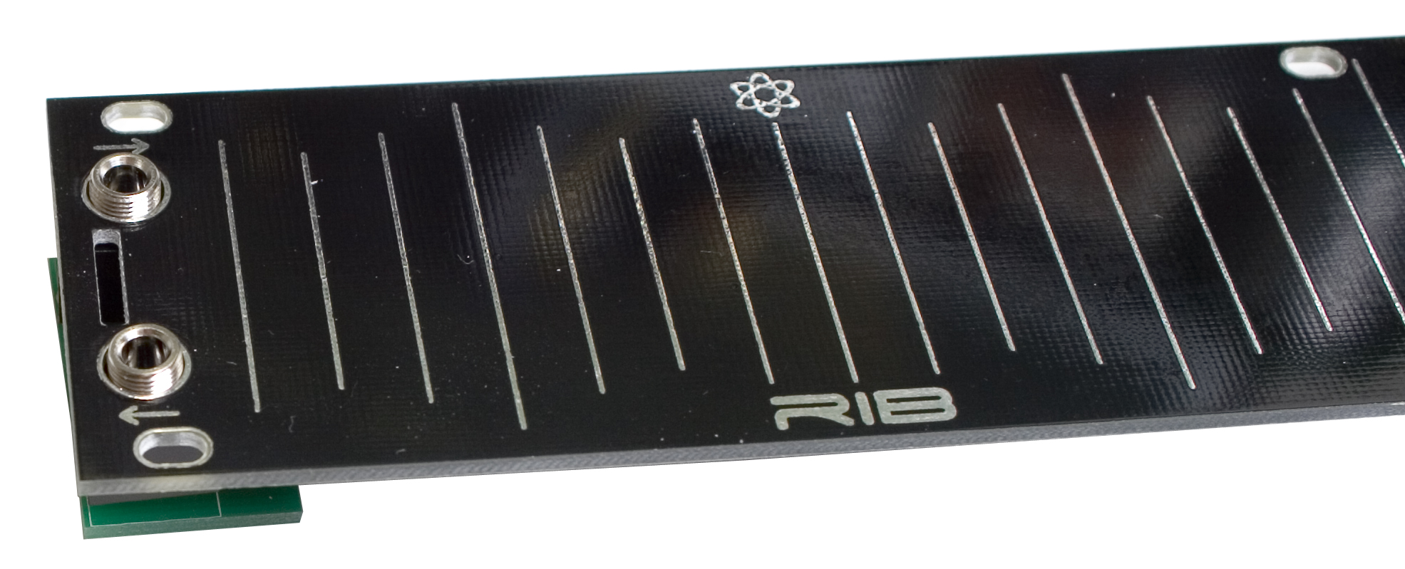
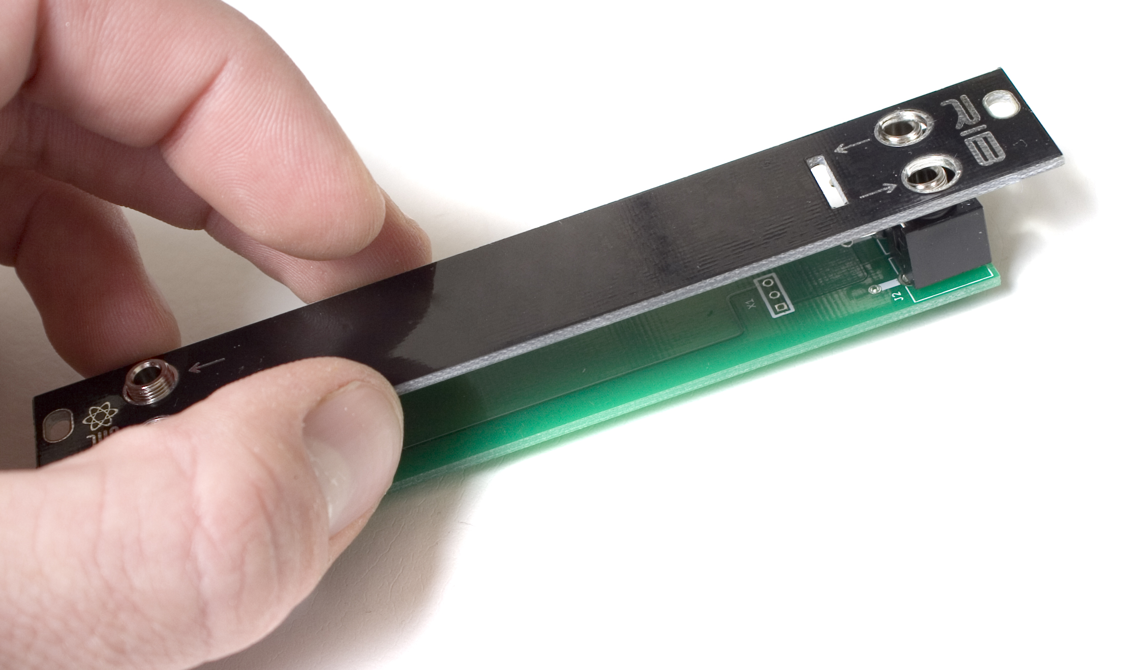
Carefully flip your project over and take a careful look at the PCB. It will be able to slide around just a little bit. Align it so that the edge of the PCB is lined up with the end of the front panel. If the PCB extends out beyond the front panel, you will run into fitment issues when you try to install it in your case.
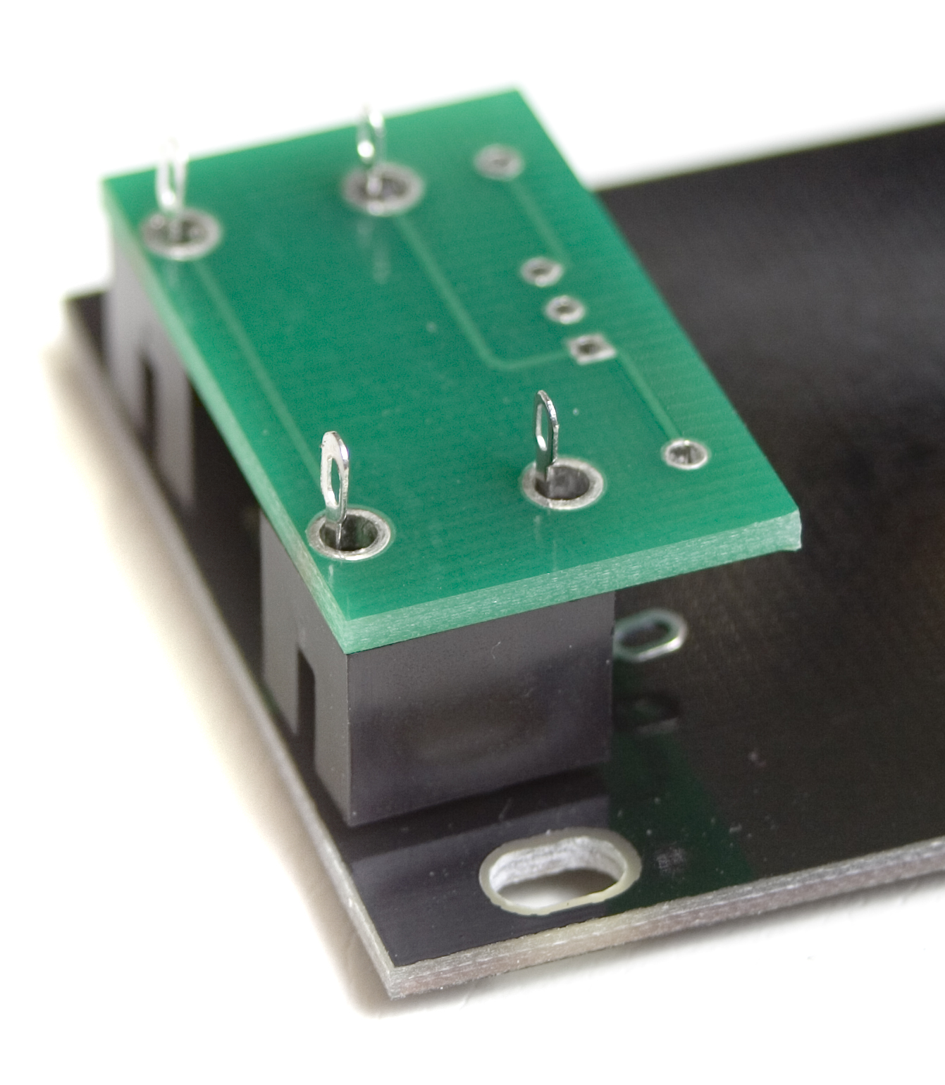
Proper fitment of the PCB on the back of the panel.
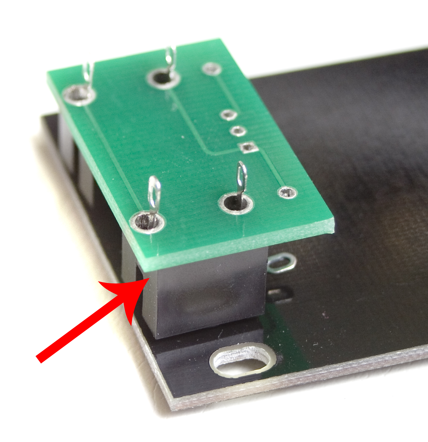
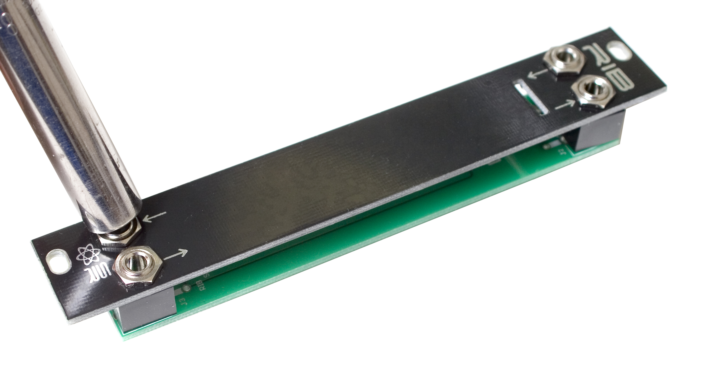
Improper fitment of the PCB on the back of the panel.
In the picture above, take a close look at the red arrow. Notice how the PCB overhangs the front panel. DO NOT solder your jacks like this!
Once you are happy with the way the PCB looks, solder your jacks in place. Clipping the legs of the jack is optional, and only really needed if you have an extremely shallow case.
TRS Jack Ground Leg
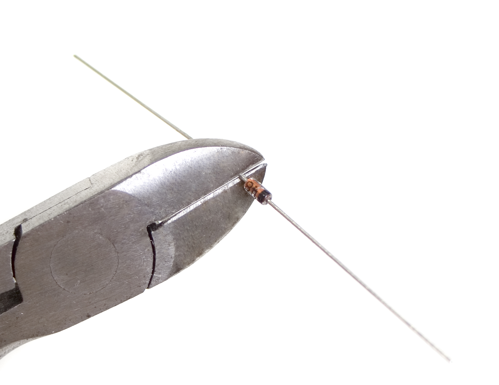
Next up we are going to be soldering in the ground leg for the TRS jacks. Grab the diode(s) that came with your kit, and clip the legs off of it, making sure to clip it close to the body of the diode. You can discard the body part of the diode.
Next, carefully slide your diode leads through the solder pad for the Ground leg of the jacks. Make sure that the leads go through the ring on the jack’s leg. A tool, like tweezers or small pliers can help with the alignment of the leads.
Once you have them properly aligned, go ahead and solder them in place, clipping the excess that hangs out of the PCB. If you are having a hard time reaching the ground leg that is between the PCB and Panel, you can wait until the next step when we take the assembly back apart, and then solder it.
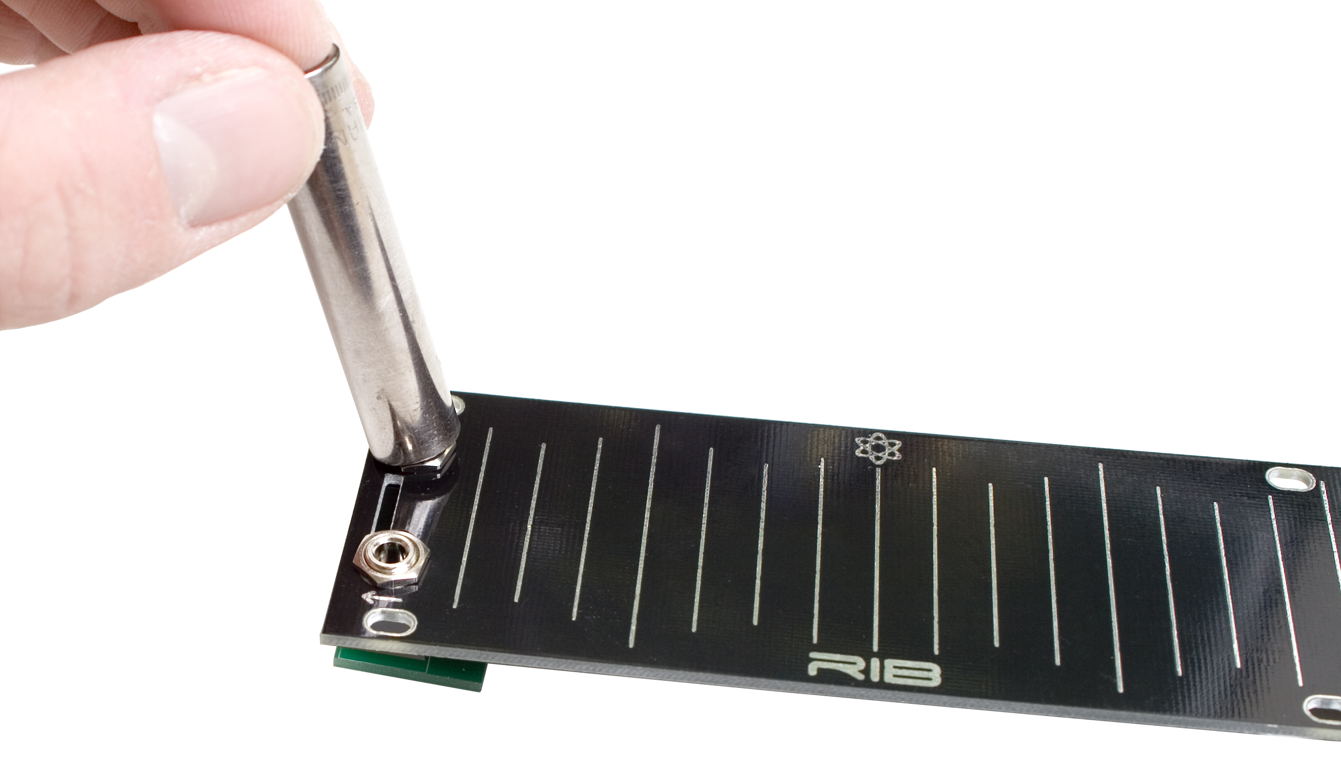
SoftPot Placement
Now we are ready to stick the SoftPot to the front panel. Start by disassembling your project, and set the PCB part aside for now.
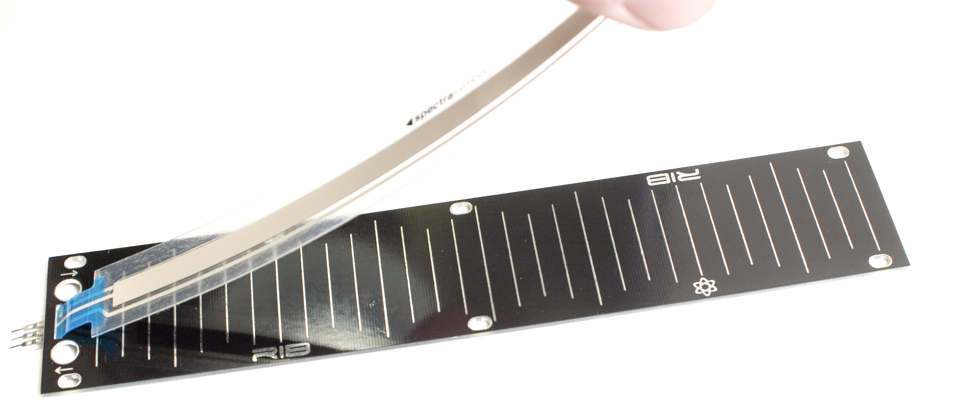
Set the SoftPot on top of the Panel (without peeling off the back) so that you can get a good idea of how it is going to get stuck down. This part is important, because once you stick the SoftPot down, that’s it. No changing it.
You will notice that it is just slightly too long to fit on the panel. This is fine, as we will be trimming it down in a minute.
Line up the SoftPot so that the ‘tail’ part (the skinny part with the pins) is lined up with the slot, and the beginning of the wider part is right up to the holes for the jacks. When you stick it down, make sure that you get it as close to the jacks as possible, as if it is too far away, when you trim the excess off the end, you could actually damage the potentiometer.
Next up, carefully peel the protective backing off the SoftPot, making sure not to touch the sticky part.
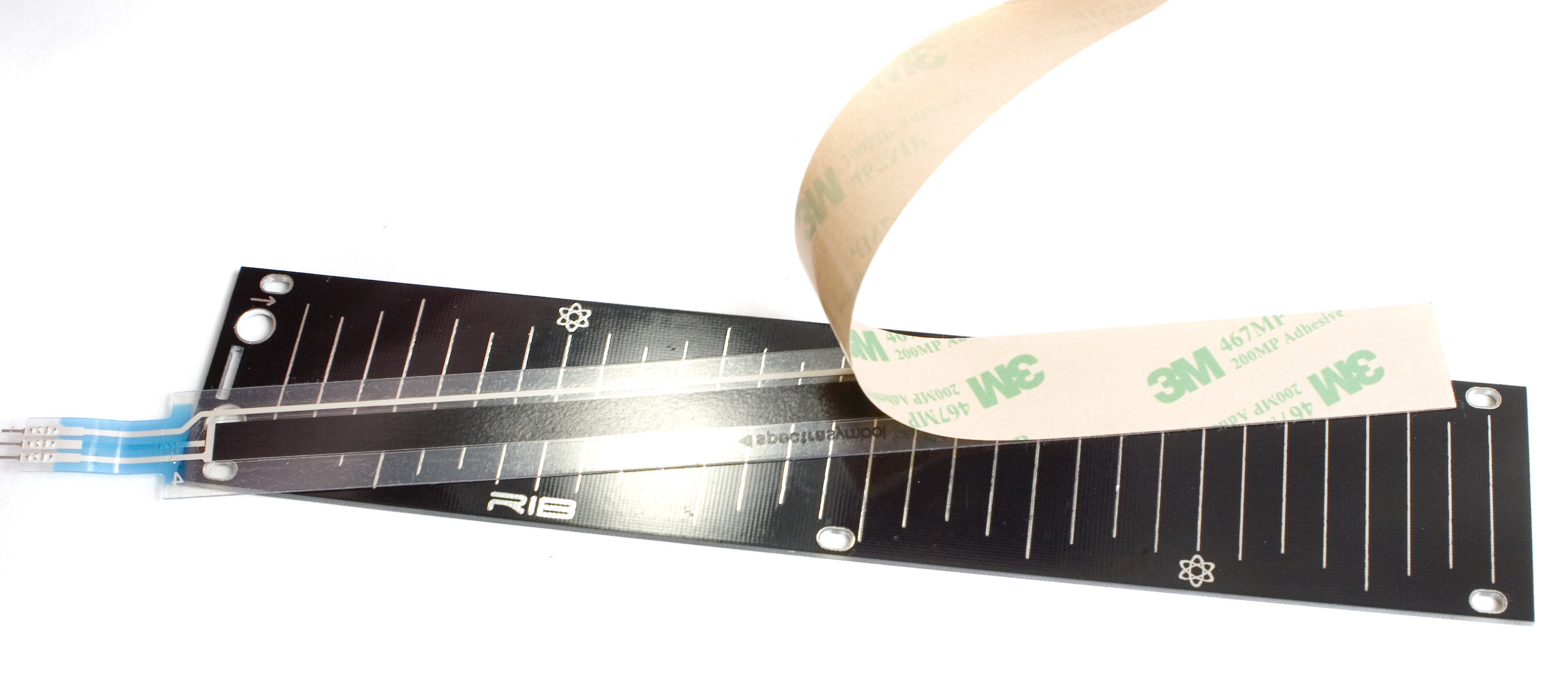
Next, insert the ‘tail’ portion of the SoftPot through the slot in the Panel, and CAREFULLY stick the SoftPot down, starting with the ‘tail’ side of it, and moving to the right. It may help with alignment to just barely stick the two ends down first, then finish by sticking the rest down.
Remember to get the SoftPot as far to the left as possible!
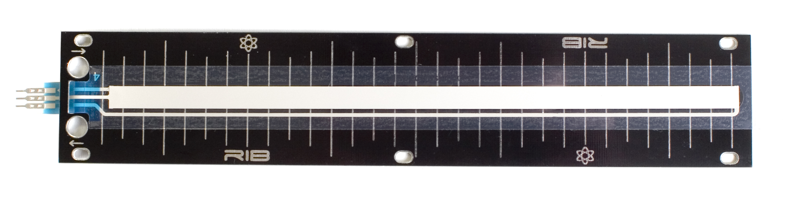
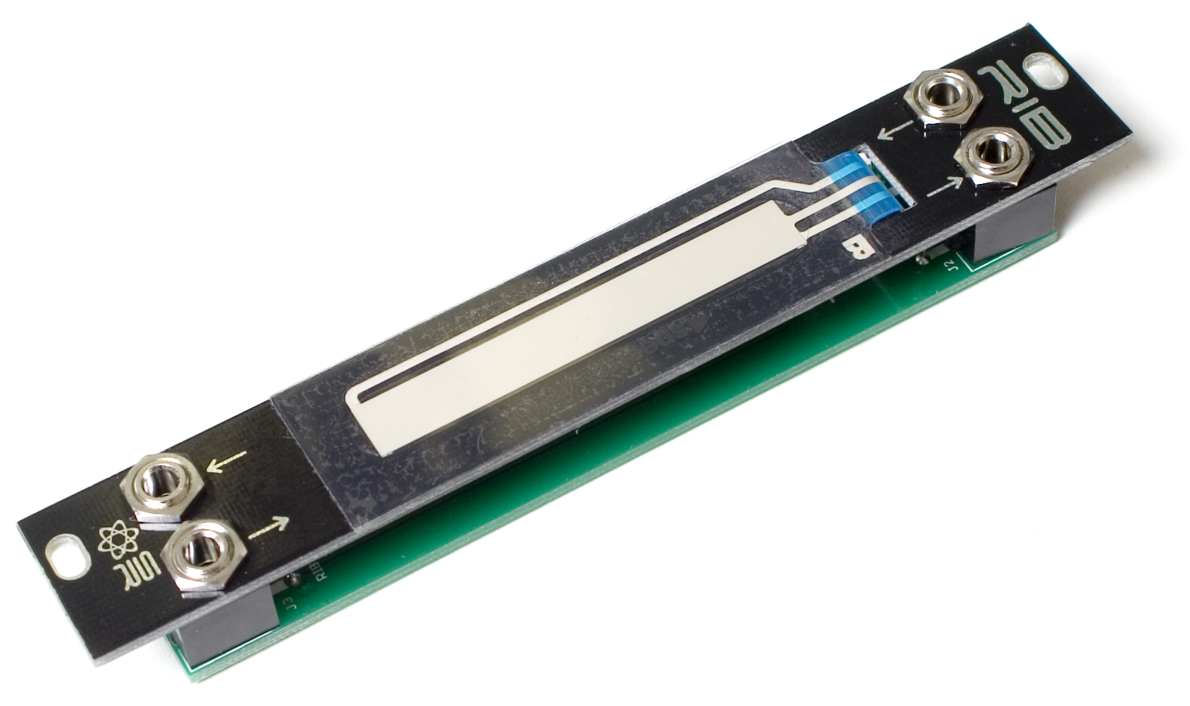
 Once fully adhered, your project should look like the photo below.
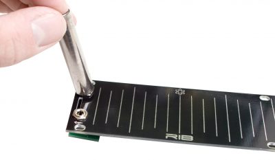
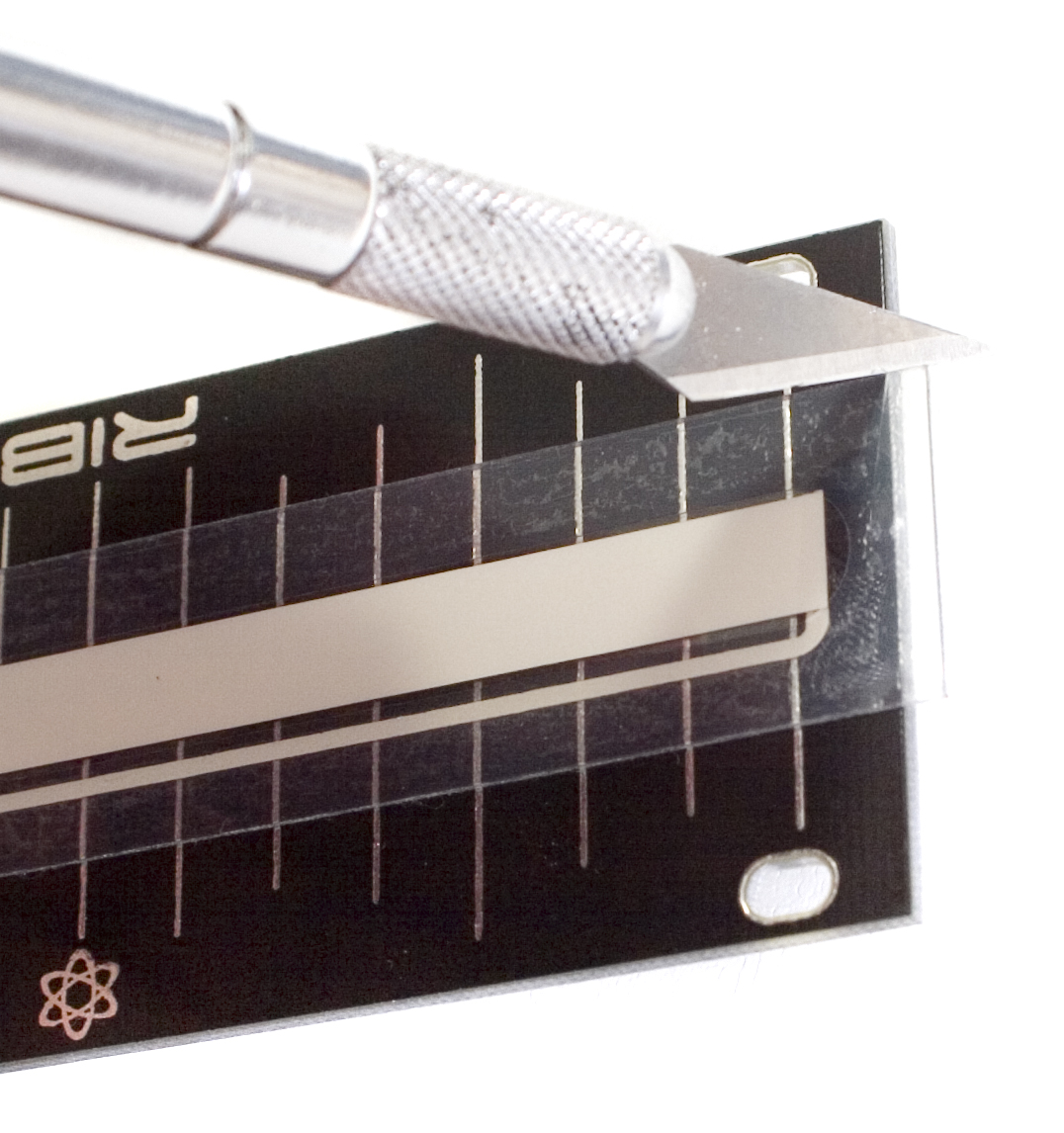
 Next, grab a craft knife or exacto, or other really sharp knife, and carefully trim the excess off the end of the Panel.
Final Assembly
Now we are ready to re-assemble the two parts of the project.
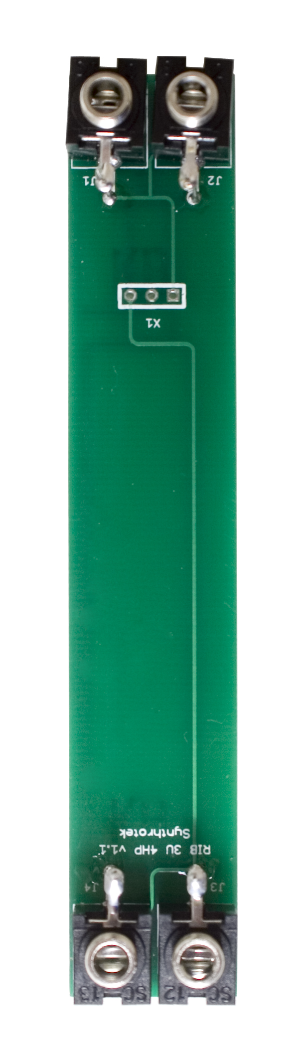
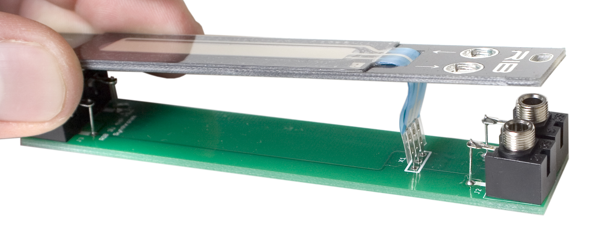
Start by inserting the three pins of the SoftPot into their proper holes marked X1 on the PCB.
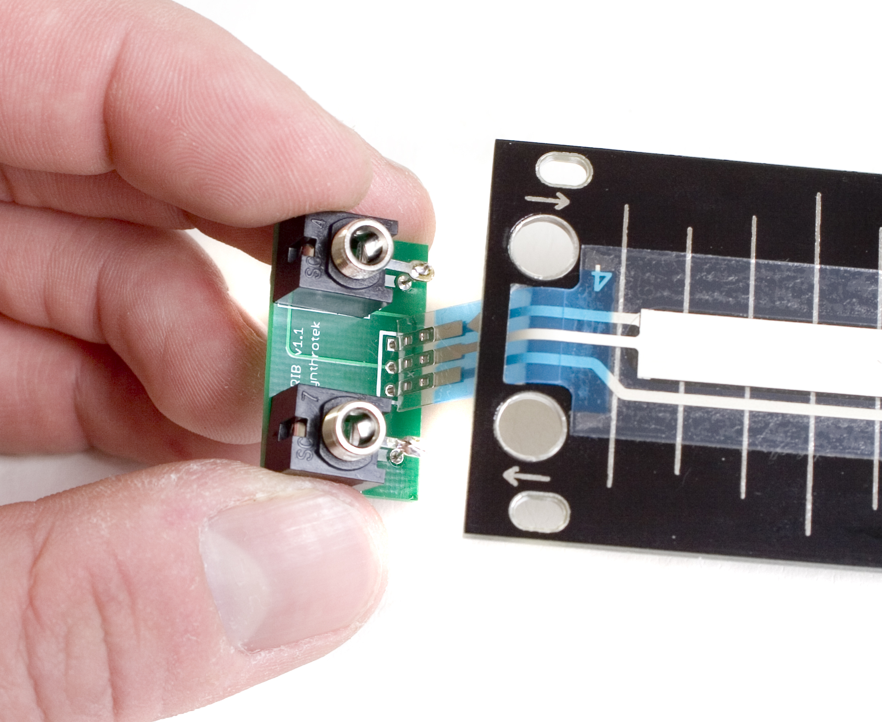
Next, insert the assembly into the jack holes in the panel. Make sure to keep an eye on the ‘tail’ of the SoftPot to ensure that it folds up underneath the panel. If you don’t, it will try to push back up through the slot and un-stick the end of the SoftPot, or damage the SoftPot.
Thread the nuts onto the jacks, and tighten them down with a tool. Once you are happy with how the tail of the SoftPot is sitting, carefully flip your project over and solder it into place.
Completed Unit
Congratulations! You just completed the Synthrotek Ribbon Controller 1U Touch Interface! All that’s left is to install it in your rack, and patch it into the MST Ribbon Controller, and make some noise!
3U Ribbon Controller Touch Interface Assembly Instructions
Jacks
First up, we are going to put the two TRS jacks in the board. Insert them through the PCB in the proper spots, as shown below. Don’t solder them in yet, as we need to make sure they align with the panel properly.
*Due to manufacturing tolerances, if you have v1.1 of the PCB, you may need to trim one of the legs of the jack for it to fit into the board.
First Assembly
Next, fit the panel over the jacks, and hand tighten the nuts on the top of the panel. You can then twist the jacks slightly so they are aligned straight with the panel and PCB.
 Then, using a tool, tighten the nuts down so the jacks can’t move around any more.
Once everything is aligned properly, carefully flip your project over and solder all the jacks in place. Clipping the legs of the jack is optional, and only really needed if you have an extremely shallow case.
TRS Jack Ground Lead
Next up we are going to be soldering in the ground leg for the TRS jacks. Start by disassembling your project, and setting the front panel aside for now.
Grab the diode(s) that came with your kit, and clip the legs off of it, making sure to clip it close to the body of the diode. You can discard the body part of the diode.
Next, carefully slide your diode leads through the ring for the Ground leg of the jacks. Make sure that the leads go through the solder pad on the PCB below the ground leg. A tool, like tweezers or small pliers can help with the alignment of the leads.
 uOnce you are satisfied with how all of the leads are situated, solder them all in place, and clip the excess that is sitting above the jack.
SoftPot Placement
Now we are ready to stick the SoftPot to the front panel.
Set the SoftPot next to the Panel (without peeling off the back) so that you can get a good idea of how it is going to get stuck down. This part is important, because once you stick the SoftPot down, that’s it. No changing it.
Line up the SoftPot so that the ‘tail’ part (the skinny part with the pins) is lined up with the slot, and the beginning of the wider part is right up to the holes for the jacks. When you stick it down, make sure that you get it as close to the jacks as possible, as if it is too far away, when you trim the excess off the end, you could actually damage the potentiometer.
Now, carefully peel the protective backing off the SoftPot, making sure not to touch the sticky part.
Next, insert the ‘tail’ portion of the SoftPot through the slot in the Panel, and CAREFULLY stick the SoftPot down, starting with the ‘tail’ side of it, and moving away from it.
 Final Assembly
Now we are ready to re-assemble the two parts of the project.
Start by inserting the three pins of the SoftPot into their proper holes marked X1 on the PCB.
Next, insert the assembly into the jack holes in the panel. Make sure to keep an eye on the ‘tail’ of the SoftPot to ensure that it folds up underneath the panel. If you don’t, it will try to push back up through the slot and un-stick the end of the SoftPot, or damage the SoftPot.
Thread the nuts onto the jacks, and tighten them down with a tool. Once you are happy with how the tail of the SoftPot is sitting, carefully flip your project over and solder it into place.
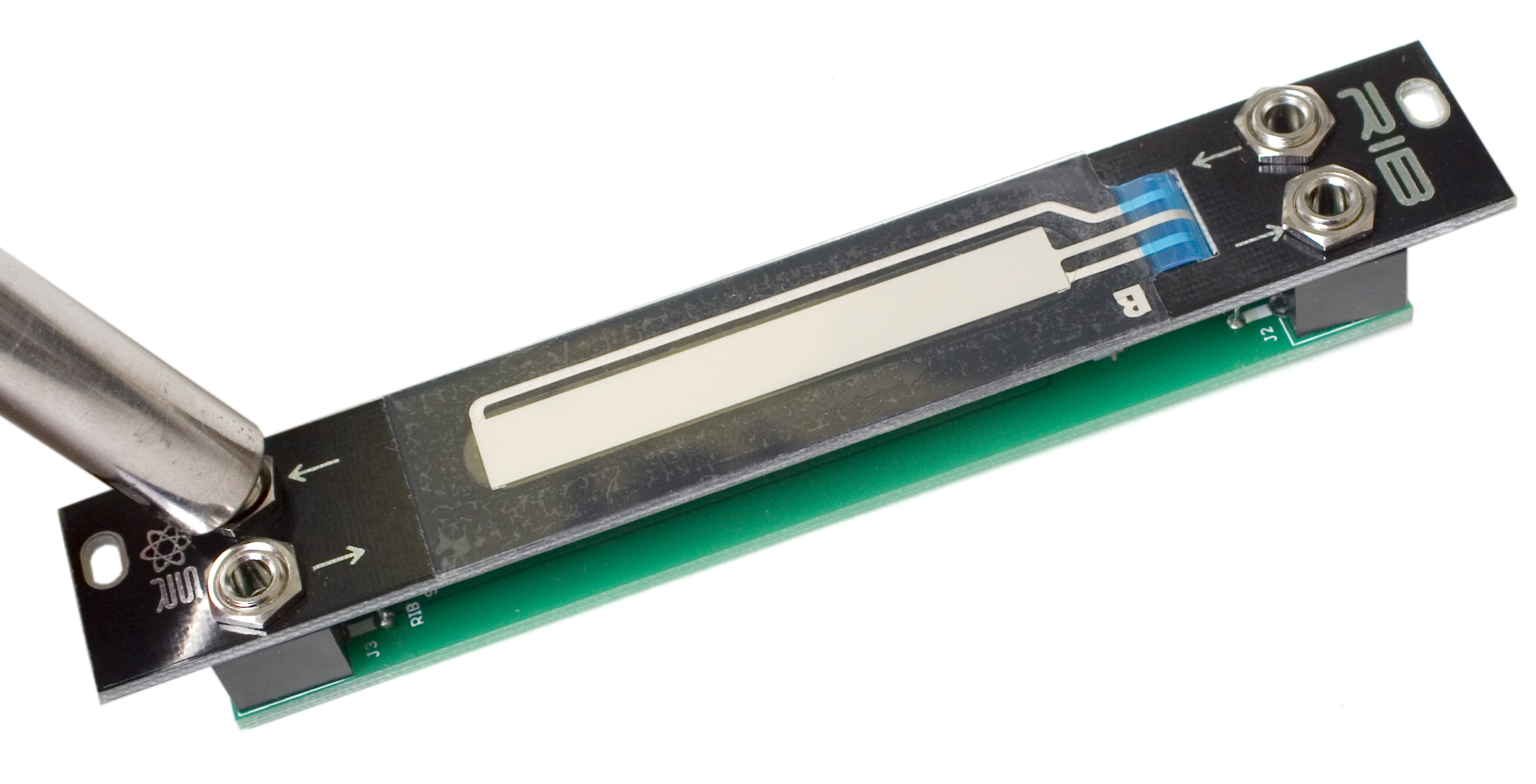
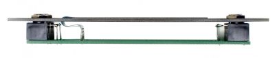
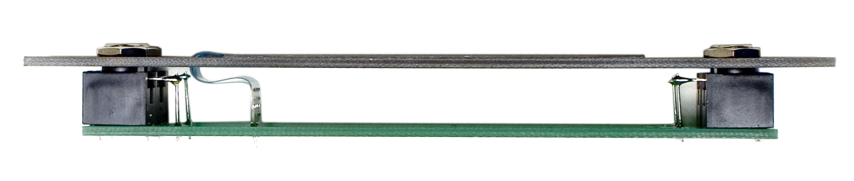
Below is a picture showing what the tail section of the SoftPot should look like when folded under the panel.
 Completed Unit
Congratulations! You just completed the Synthrotek Ribbon Controller 1U Touch Interface! All that’s left is to install it in your rack, and patch it into the MST Ribbon Controller, and make some noise!
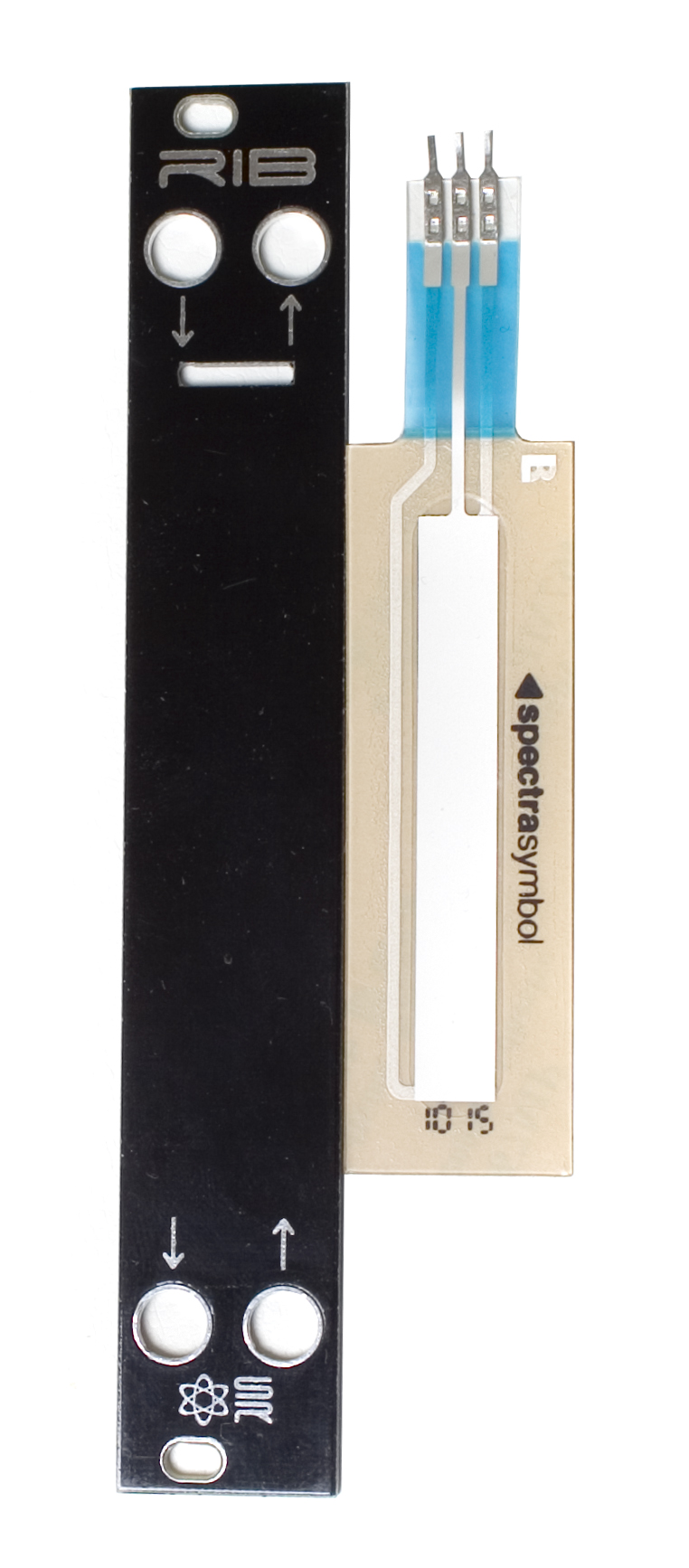
Riblet Assembly Instructions
The following assembly instructions are for the Riblet, which is a DIY interface for the MST Ribbon Controller Interface. The instructions listed below only show a couple of the options available to you, as you can build it however you would like to suit your needs. Get Creative!
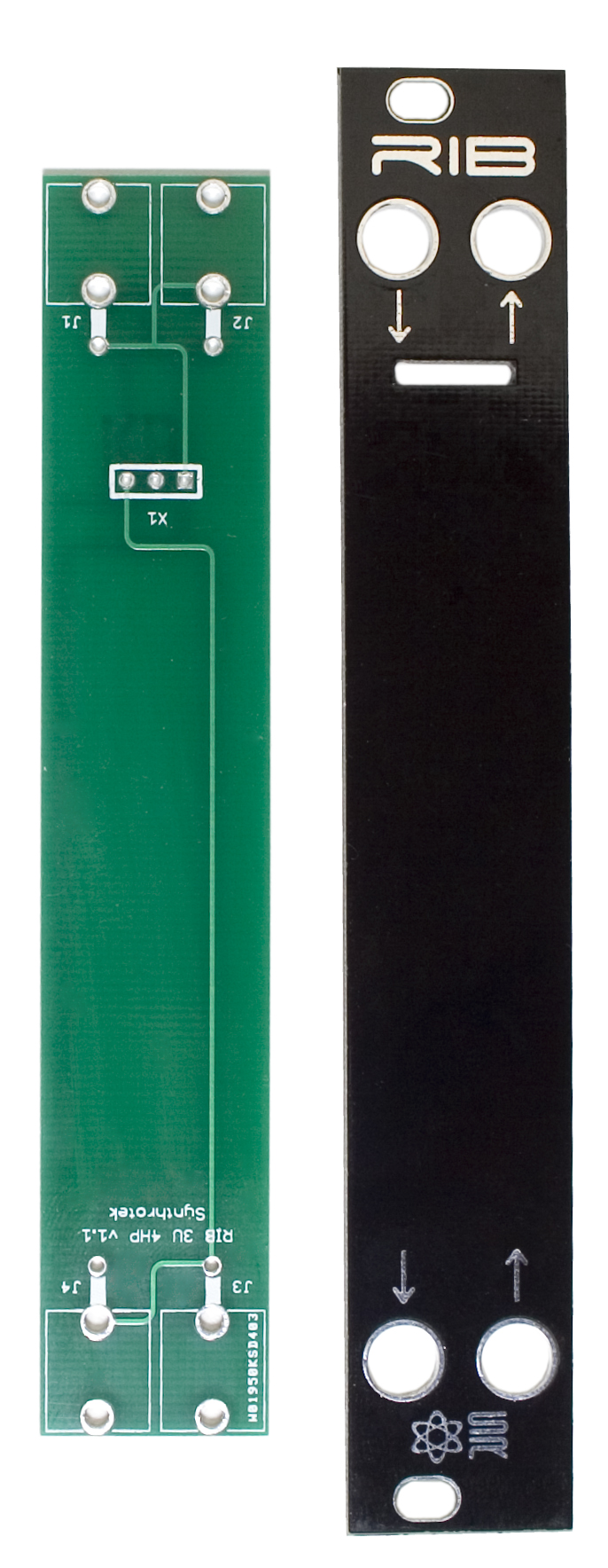
TRS Jack
First up is the Jack. You can either use the side mount jack that we include in the kit, or wire in your own. Just keep in mind it HAS to be a stereo TRS jack, or this will not function correctly with the MST Ribbon Controller Interface.
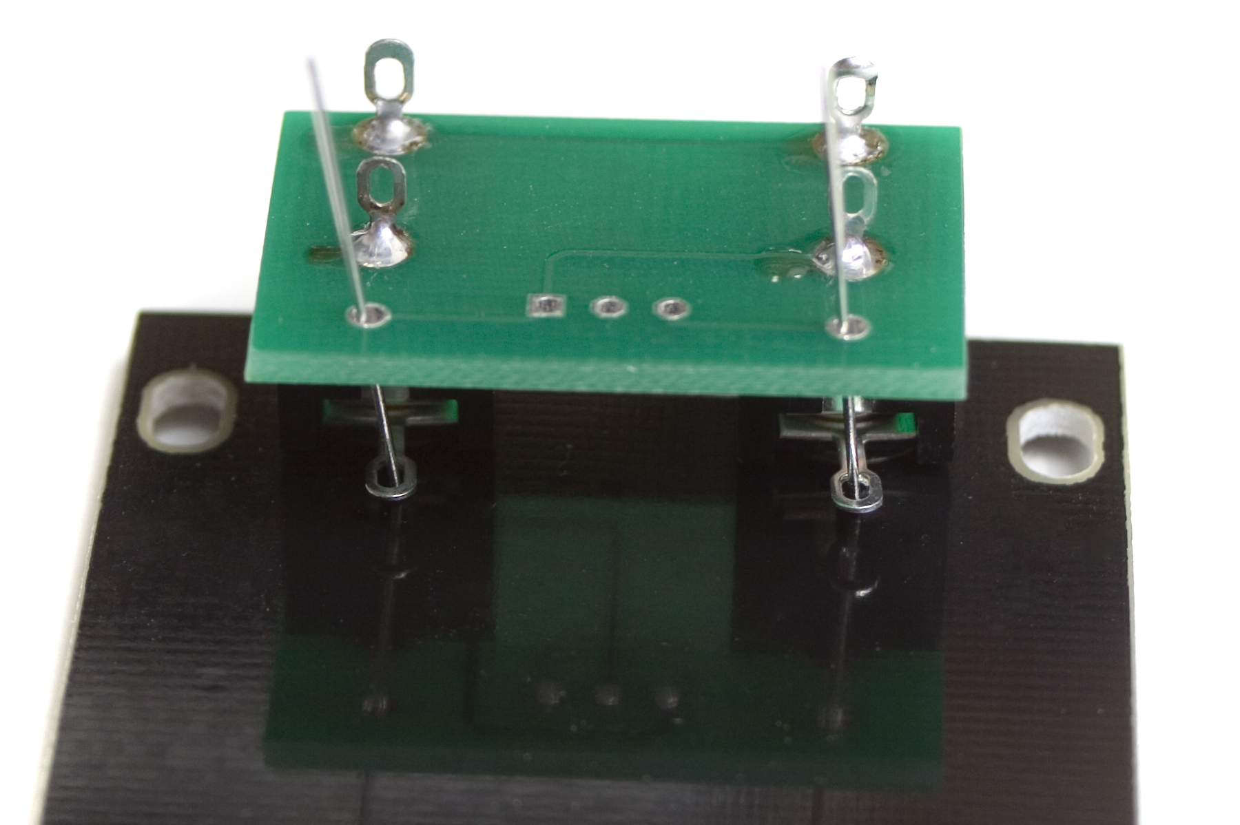
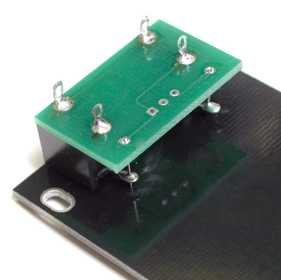
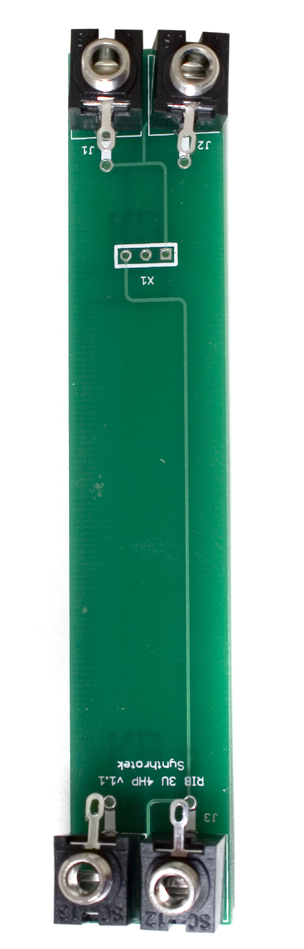
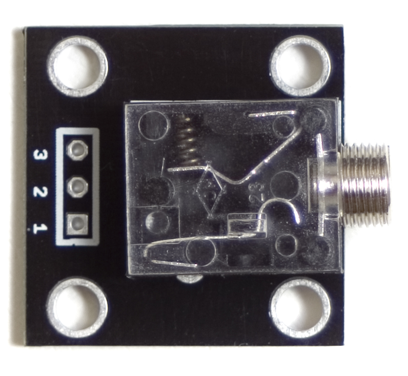
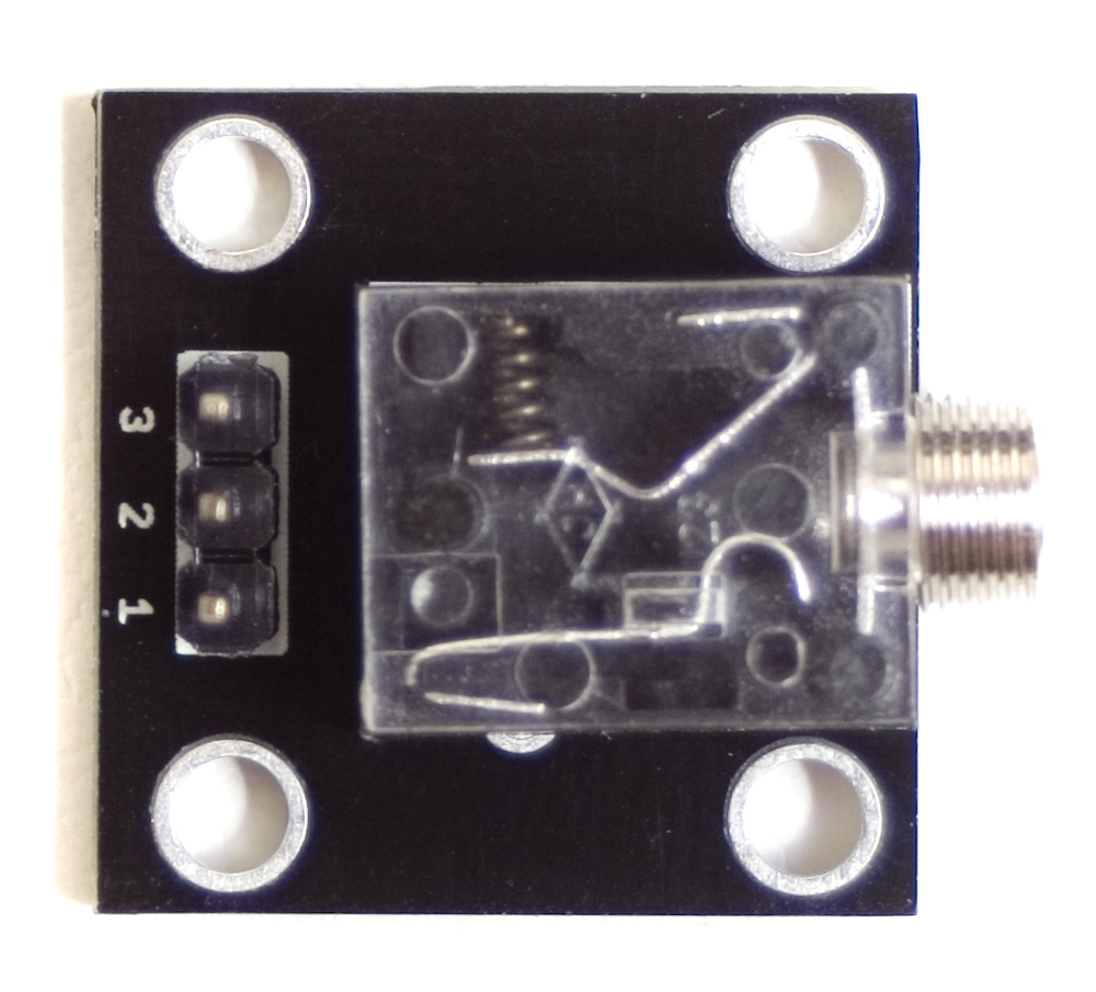
If you’re using the included jack, populate it as shown below, and solder it in place.
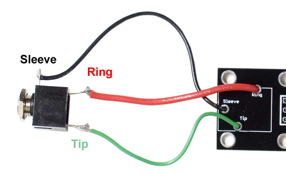
 If you would like to use your own TRS jack, an Example is shown below with a 3.5mm TRS jack.
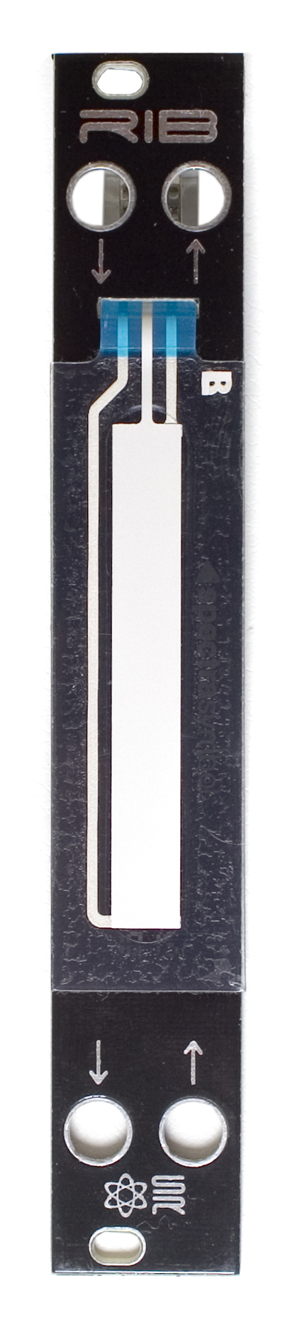
SoftPot
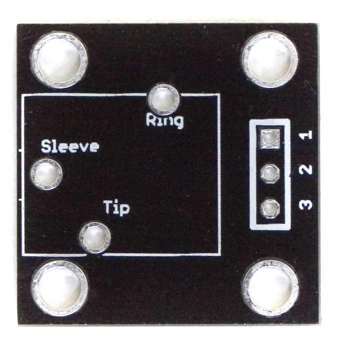
When it comes to attaching the Softpot, you can either solder the SoftPot directly to the PCB, or use a 3 pin header, and wire it in yourself.
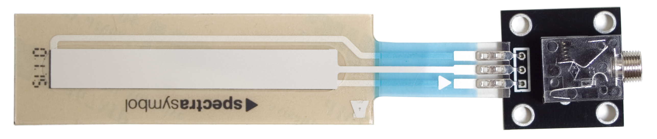
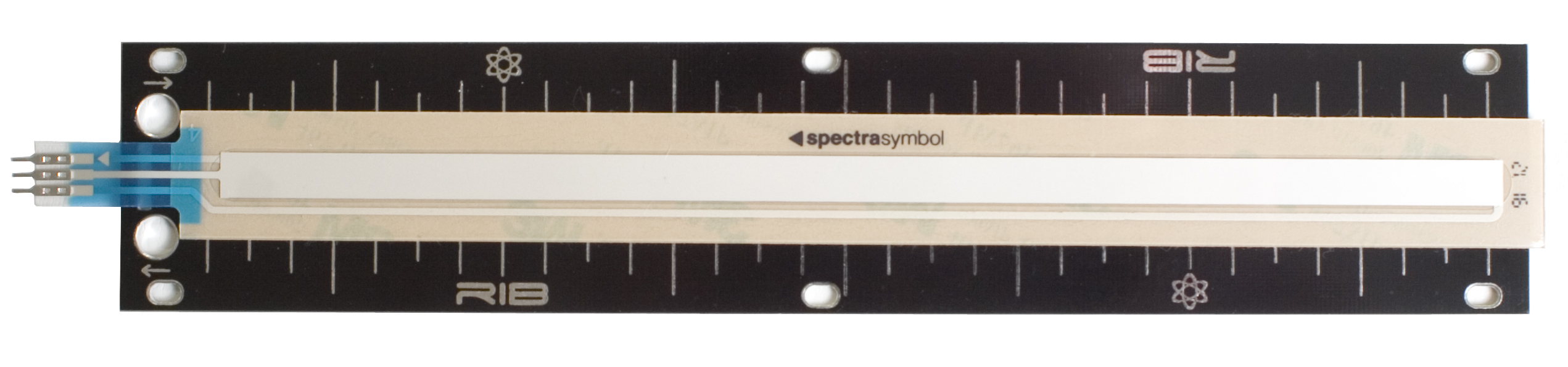
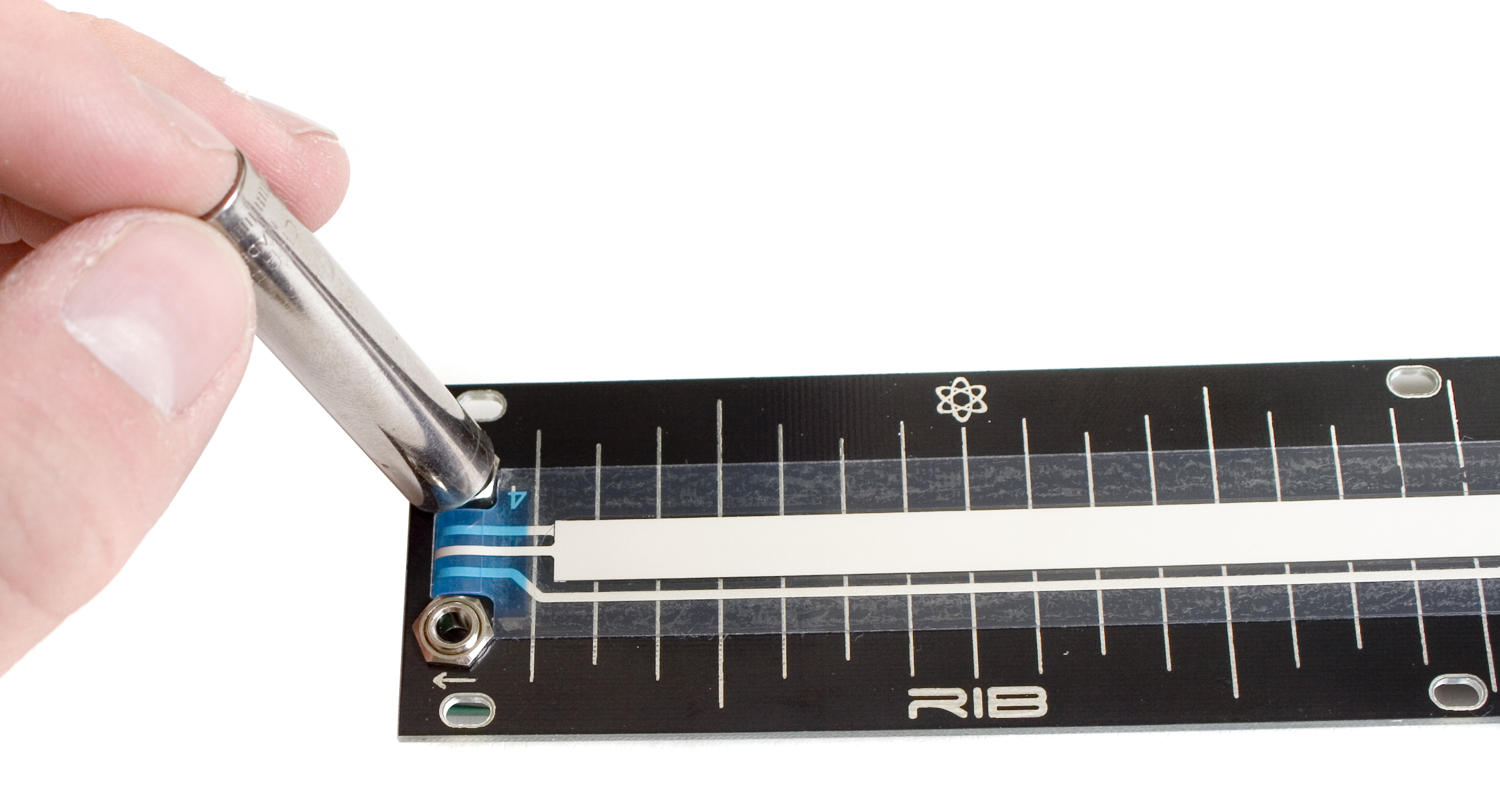
Make sure that if you are soldering the SoftPot directly to the board, to line up the pin with the arrow marker to the solder point labeled “1”, which also has a square solder pad.
If you are using a three pin header and wiring it yourself, Make sure that when you wire the SoftPot in, that you connect the pins properly to the header, or else your SoftPot will go the opposite direction.
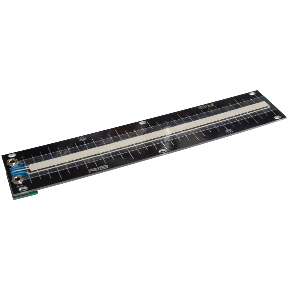
Congratulations!
You should now have a completed Riblet! You can now stick it to your surface of choice by either using the screws and spacers provided in the kit, or using some double stick tape, or even glue it down if you want!
If, for some reason, you are having trouble getting your Riblet working, check out our Troubleshooting guide, or shoot us an email at store@synthrotek.com