


Important Links
Store Page
Assembly Instructions
Bill of Materials
Mods Page and BOM
PT2399 Datasheet
Capacitor and Resistor Lookup Guide
Welcome to Synthrotek PT2399 Delay Pedal Assembly Instructions! This step-by-step guide will take you through the whole circuit-building process. Once you’re done, check out the Mods section below to find some ways to increase the functionality of your circuit or just make some crazy sounds! Let’s get started!
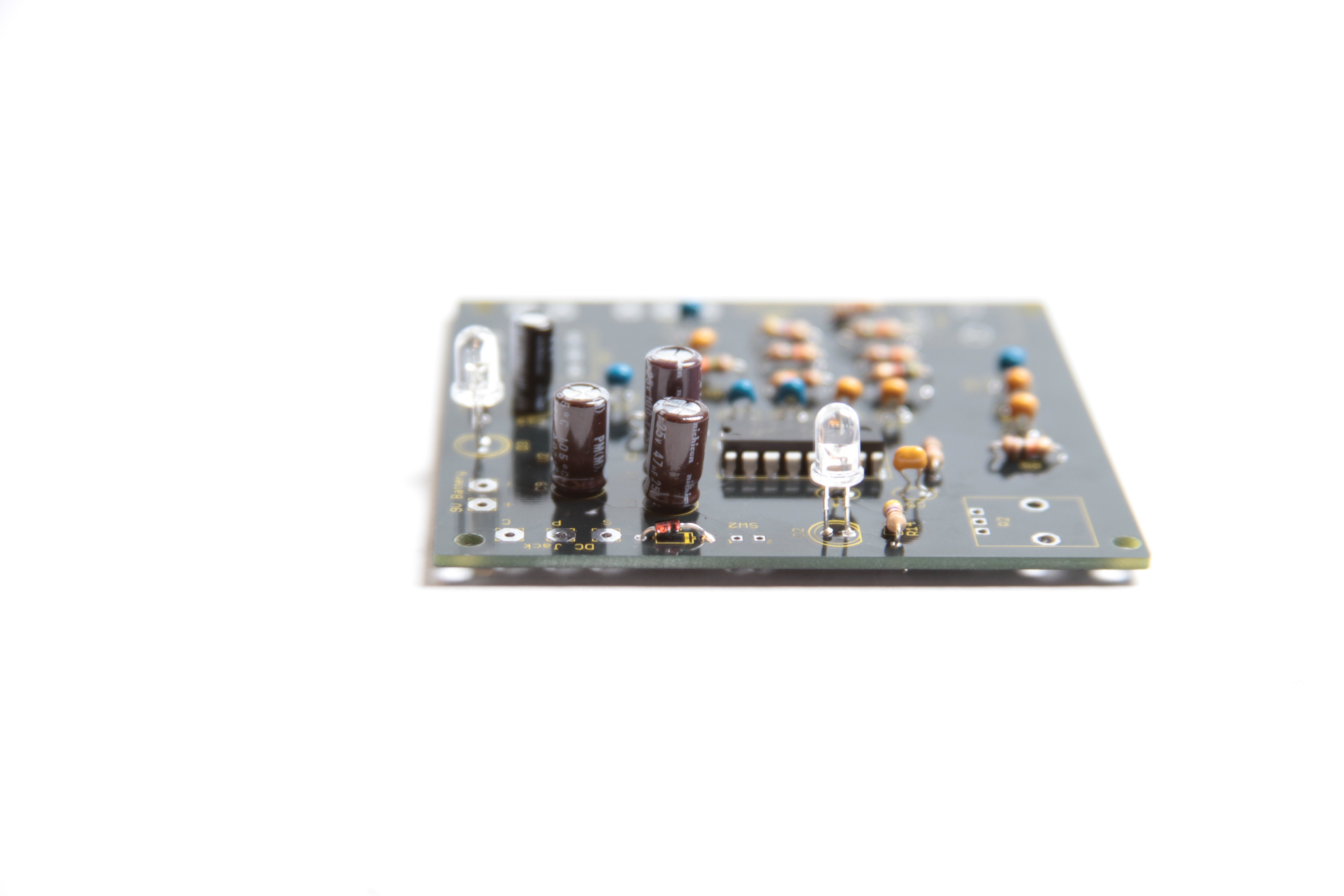
Component Layout
The first step in any successful DIY electronics project is to make sure that you have all of the parts and know their reference ID for proper board placement. Check the contents of your kit against the BOM before you begin. If you’re missing anything, send us an email and we’ll get it out to you ASAP.

PT2399 Delay Pedal Kit
Got all of your components? It’s time to start building.
Assembly
The first part of our build will be for components that are soldered directly to the circuit board. This makes the build process easier than having to deal with wires and floating potentiometers getting in our way while we solder sensitive components.
IC Sockets

PCB w/ Sockets
The first components to solder to our PCB are the IC Sockets. Insert the IC Sockets into the PCB at the points according to the image on the top layer. The Sockets have a half-circle notch that identifies pin placement. See the picture if you are unsure.
Resistors

PCB w/ Resistors
Insert the resistors into their respective PCB positions and solder them to the board. Don’t worry too much about damaging resistors with your soldering iron; resistors are not fragile components.
Note: the above picture was for a previous BOM. Check our current BOM for the correct part values. R2 and R7 have been changed. Also, R9 may be omitted from your circuit if you are not using
Capacitors

PCB w/ Capacitors
There are two different types of capacitors in this circuit. Electrolytic capacitors (C2, C3, C9, and C14) are polar components and their pcb placement matters. The shorter lead and the band on the body identifies the negative lead, which will be inserted into the circle through-hole. The positive lead will be longer and should be inserted into the square through-hole.
Polarity is not an issue with the remaining ceramic capacitors. Just be sure the component values are identified before soldering them; some of them look very similar and the codes printed on their bodies are the only way to identify them.
Note: C2 is optional, and you may notice a bit of filtering of your input signal. You can also change out this value to remove noise or filter a range of frequencies.
Diodes

PCB w/ LED’s
Diodes are polar components, so pay attention to their placement.
Similar to electrolytic capacitors, LEDs (Light Emitting Diodes) are manufactured with one lead being shorter than the other to identify negative polarity. Also,you will notice that there is a flat edge on the base of the LED. On the PCB, the silkscreen helps you orient your LED correctly.
If you look closely at the Schottky diode, you will notice that there is a small black band; this identifies the negative lead. Using the silkscreen as a guide, insert your diode correctly into the PCB through-hole and solder.
We are now done with all of the components that are soldered directly to the board.
(Note: on the Console version of the circuit, you can omit D3. D3 is the status LED for the Stompbox version, and your Console version will always be in the “On” state.)
Wired Components
If you have a case you want to mount your circuit into, keep this mind when consider how long your wires will need to be. Remember, keep your wires longer than you think you need them to be and you’ll save yourself a lot of de-soldering and re-soldering to get the right length.
Potentiometers

Connecting the Pots
Solder three wires to each solder terminal of the potentiometers and insert them into the PCB as shown in the picture above. Solder them to the PCB. You make find that you need to twist the stranded wire very tight to get the wire through the PCB.
(Note: for proper clockwise operation of the circuit, you will need to switch the “1” and “3” connections of the Feedback and Delay Length potentiometers.)
Power Supply

Power Supplies
The PT2399 Delay circuit is designed to use two power supplies, a 9V battery and a DC source (such as an AC Adapter). If you leave a 9V Battery plugged into the circuit and then insert a DC Plug, the 9V Battery will be unplugged from the circuit. This will leave you with a back-up power supply should your DC Jack be yanked out during a show and save you some money on replacing accidentally on-all-night dead batteries.
If you do not want to use a DC source, solder a wire from ‘S’ to ‘C’ of the DC Jack and your circuit will now solely use a 9V battery as a power supply. If you do not plan to use a 9V battery, leave the 9V battery adapter clip off the circuit. You can always install it later or use it for another project. If you want both, read on.
Insert the red wire of the 9V Battery into the through-hole marked ‘+’ and the black wire into the through-hole marked ‘-‘. Solder the wires to the PCB.

Power Jack
There are three terminals located on the back of the DC Jack. Make sure to identify each wire before soldering it to the corresponding PCB through-hole. Use the pictures above as guides.
If you have a different type of DC Jack, the diagram below identifies the solder terminals that correspond to the same PCB through-holes for the DC Jack.

Power Jack
If you do not want to install the 9V DC jack and only install the 9V battery clip you will have to short the S and C pins for the 9V DC Jack like shown in the picture below*.
* Your PCB may not look exactly like the photo, that is ok. What is important is that you short the same pins as shown in the photo.
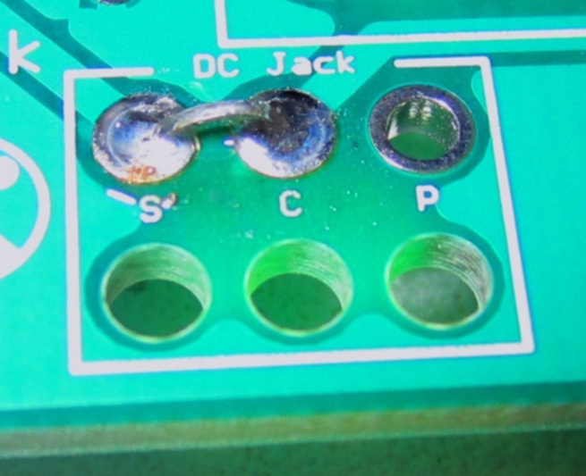
Short these contacts to get the circuit to work without the 9V DC Jack
Input/Output Jacks

Input/Output Jacks
The wiring for the three-terminal stereo jack is very important for the circuit to function. The circuit will not receive power until a mono cable is plugged into the ‘IN’ jack, saving battery power when the circuit is not being used. If you are using a mono jack for ‘IN’, solder a jumper wire from ‘R’ to ‘S’.
If you received the jacks shown above (two sets of solder terminals), make sure that you solder to the terminals show in the picture and not the other ones. These are called switched jacks and they are very useful when we start getting into modifications for our circuit.

Jumper Wires
If you’re building the console version (not the stomp box version) be sure to wire two jumper wires according to the picture. If you are using the D3 status LED, solder an additional jumper in the B column like you did with the other two jumpers.
Congratulations on your completed circuit!!
Read on for stomp box instructions
Switches (stomp box version)

Stomp Box Version (switch and 1/4″ jacks)
This picture is for the stomp box version. The stomp switch is wired horizontally onto the board.

Stomp Switch Wiring
It can be a little tricky to get the stomp switch on correctly, use this picture as a guide to match up the terminals from the switch to the board.
Put the switch and the 1/4″ jacks in place.
If you have the version without mods, you’re done!
If you have the version WITH mods, check out the mod page HERE.
So… Regarding the mod mentioned in the videos… When y’all say “pin 6”, I assume you mean on the pt2399 ic — between the ic and the delay length pot. Is that correct?
Yes, that is pin 6 on on the PT2399 IC, thanks!
Hi; I have intension of using this unit with a steel guitar,a (good adjustable delay really helps) plus I love building things such as that now it is beginning to get cold again .Let me know if you think that the pt2399 delay will work for me .I have read all of the build info and kit really looks nice on the layout sheet. The dual power is a good shot. Thx. Jim (jhill10054@gmail.com)
Hi Jim, yes it should work great, our new version of this kit is great for a stomp box with true bypass. Thanks!
I am unsure which way to orient the Schottky diode on my PCB. It has square/circle holes but the printout on the pcb shows a black band on the side where the square is. Which way do I orient it?
Match the Black Band on the Diode with the white band on the diode markings. Regardless of color the bands should match in orientation.
One more question about the mod adding the 555 kit. What exactly am I connecting to pin 6 of the delay? am i connecting the audio out or is there a specific pin on the 555 that I am connecting?
PT 2399 WORK IN STEREO ?( STEREO IN AND OUT ? )
Have the ceramic capacitors changed? I received ones that do not match the tutorial and BOM on the site.
Bryan, this is probably best handled via email since it is specific to your situation. Yes there have been changes to the BOM for the PT2399 Delay. Namely those are in C14 and C15. C14 and C15 are now 100nF as opposed to the older 82nF. This small change in value here has no effect to the sounds of the delay. The 82nF cap is a non-standard value and therefore hard to source resulting in issues filling orders so we’ve changed the value to be more inline with standard values of components.
The delay was designed for only a single signal. To handle stereo the left and right channels would need to be mixed together before going into the delay.
Without seeing exactly what you are doing, I can try to speculate. If you have the 555 timer kit, I believe you would connect one of the outputs to pin 6 of the PT2399 IC, and the other to ground. You can mess around with other pins, but I think 6 is where it is at. Thanks!
Regarding the 555 timer mod – can the V+ be connected to the V+ on the the Delay Board along with the connecting the grounds in order to just use one 9v battery?
Friend, I have built that successfully but can you tell me what name should i give to the pots ..?? Any idea???
Hello, I would recommend calling them Mix, Feedback, and Rate.
Best regards,
-Patrick
Why doesn’t my pcb look anything like this? My paper say pt2399??
You probably got the PT2399 Dev Delay, you can find it here.