


Important Links
Product Page
Store Page
Bill of Materials
Drill Template
Capacitor and Resistor Lookup Guide
Attention: These are the assembly instructions for the OLD version of the Tube Screamer Wired.
If you purchased the “No Pop” version of the TS, check out the assembly instructions HERE.
Welcome to the Tube Screamer assembly instructions. The new version utilizes wired components, allowing for greater flexibility in mounting and case selection. Let’s get started!
BOM Layout
If you’ve received your kit and are ready to build, the first step is to ensure you have all of the parts and familiarize yourself with the PCB and where the parts will be going.
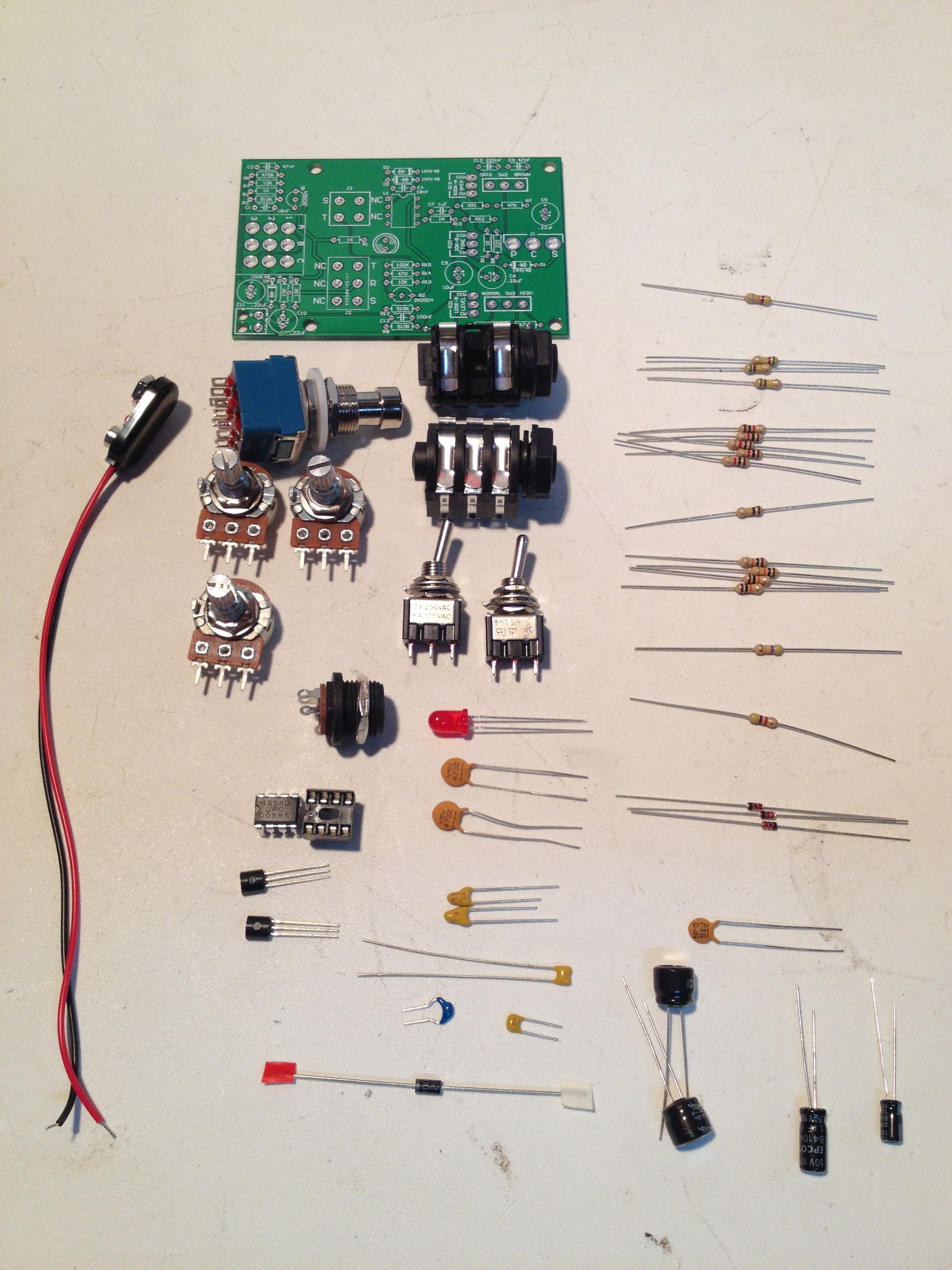
Check your kit against the Bill of Materials. If you are missing anything let us know and we will ship you the part(s).
Assembly
Attention: Changes may occur after the Assembly Instructions are created and the photos may not reflect those changes. Always use the BOM to verify the placement of components.
PCB Components
Resistors & Diodes
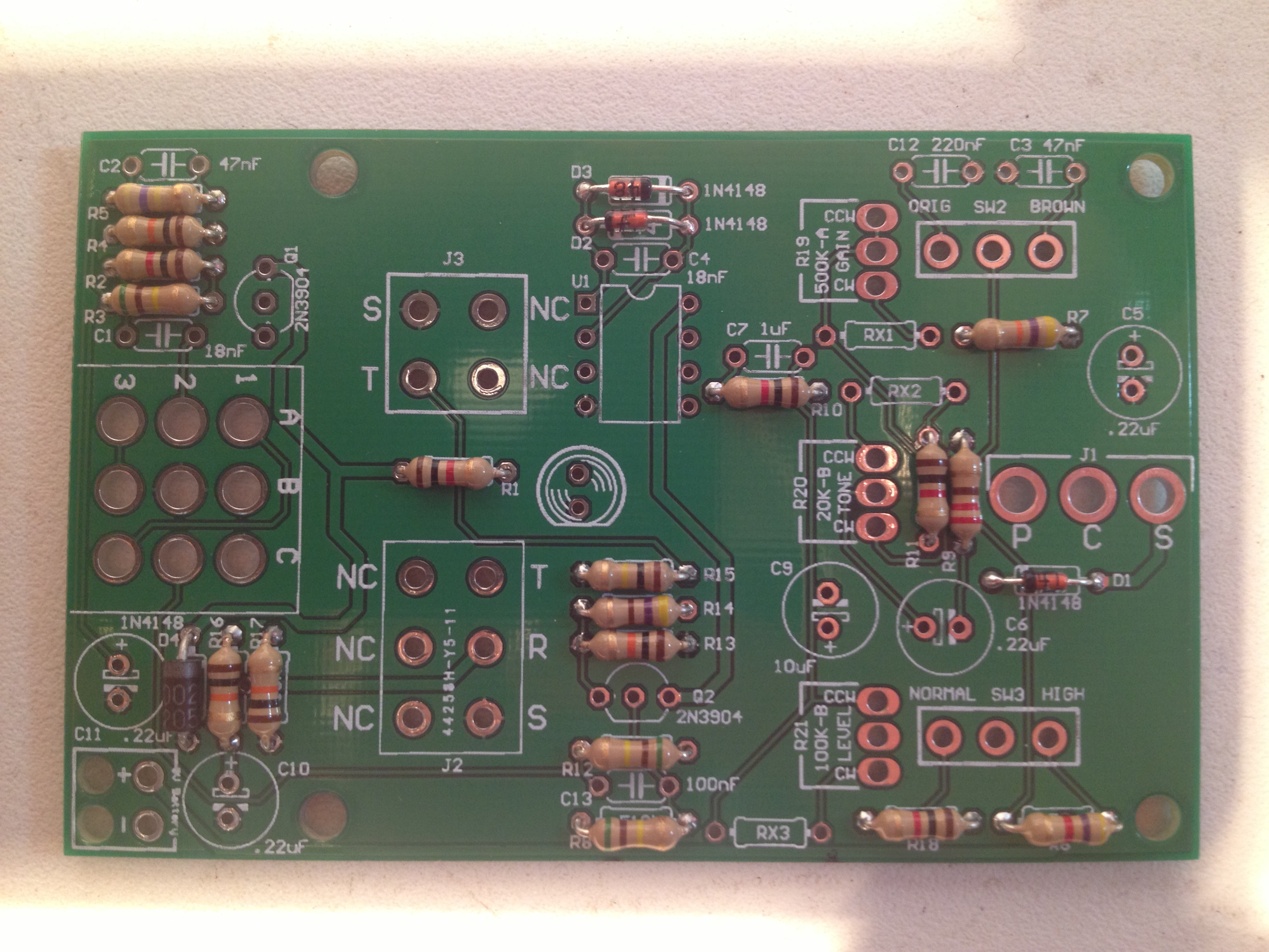
There are 18 resistors and 4 diodes to install. The resistors are not very sensitive components and are not polar, but the diodes are polar components and must be soldered in the correct orientation. On the silkscreen of the PCB for each diode there is a line on one end. You will need to match the line on the diode with the line on the silkscreen.
Capacitors
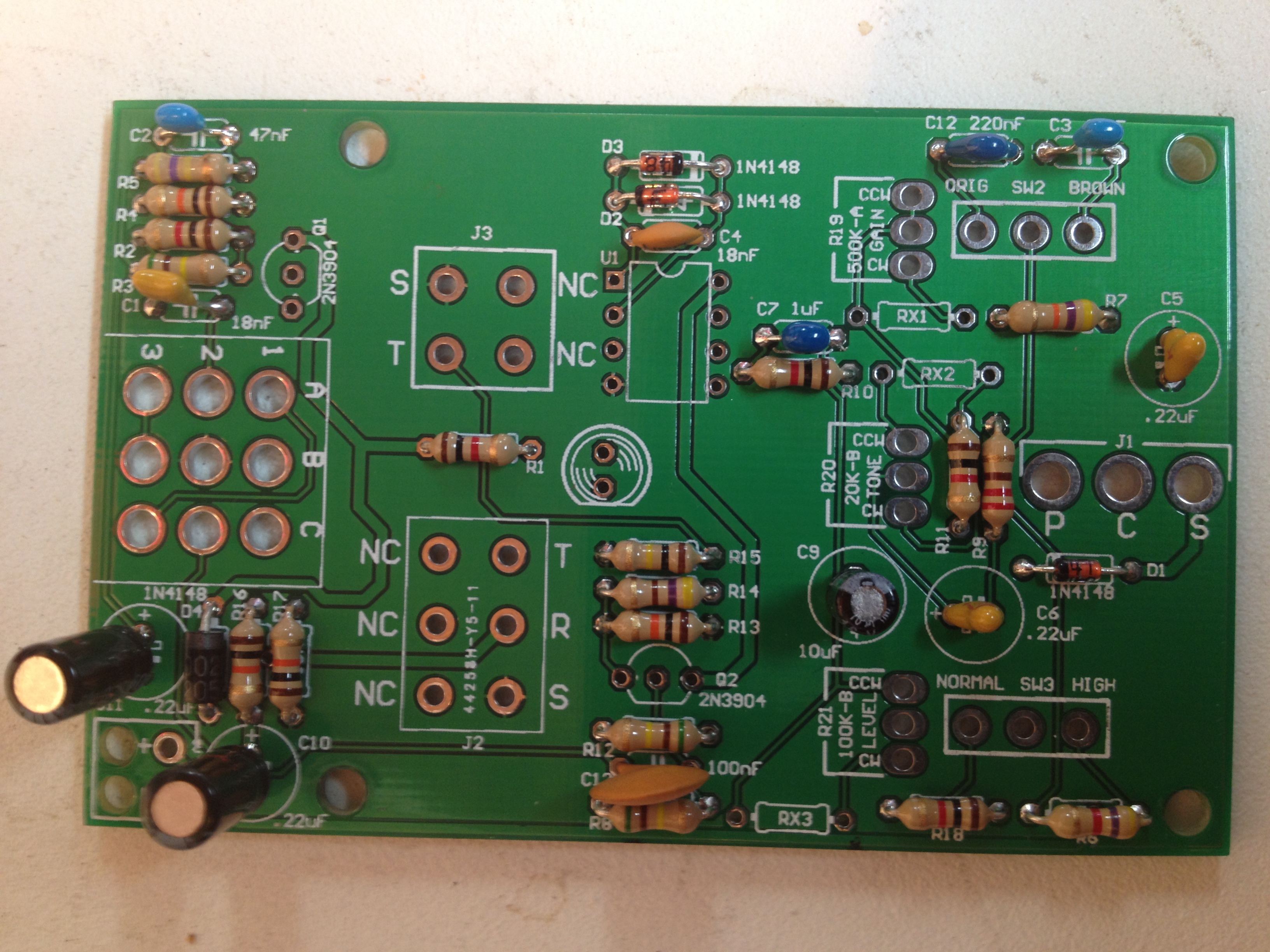
Here you will want to pay especially close attention to two of the ceramic capacitors because two of them are polar components while the rest are not. All of the electrolytic capacitors (C9, C10, and C11) are polar components. The longer lead on the electrolytic capacitors go into the hole that is marked with a ‘+’ sign. And then the two tantalum capacitors (C5, C6) that look like the other ceramic capacitors are also polar components and, like the electrolytic capacitors, you need to ensure that the longer lead gets inserted into the hole marked with the ‘+’. All of the other capacitors are not polar components and you can insert them in any direction.
NOTE: There are mistakes on the silkscreen indicating that C10 and C11 use .22uF capacitors and C4 uses an 18nf capacitor – this is NOT the case. Use 47uF capacitors for C10/C11 and 51pF for C4 as indicated on the BOM.
LED, Transistors, and IC Socket
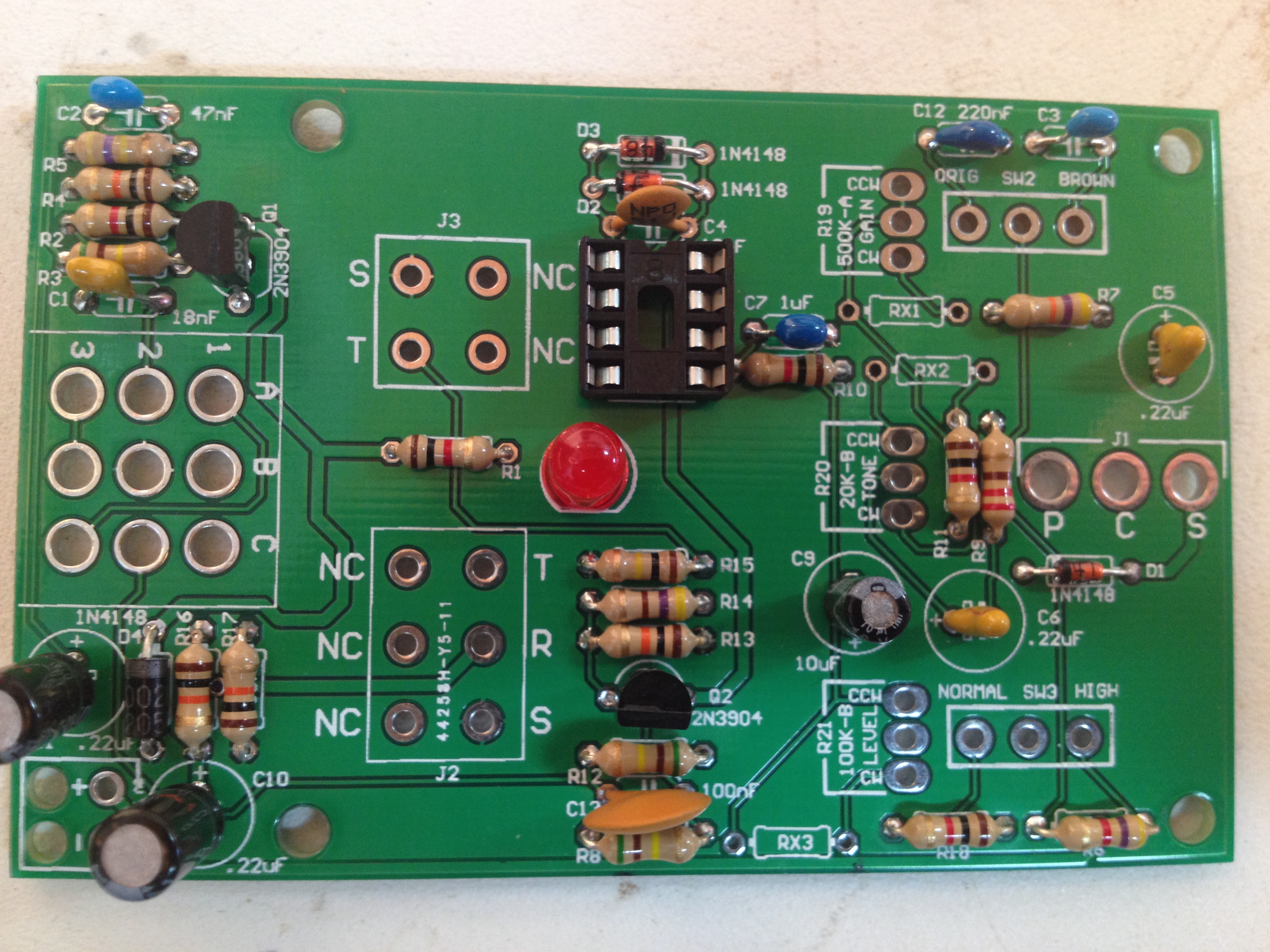
Next we will install the LED and Transistors. Both of these components have one side flat side that matches up to the silkscreen on the PCB. If you have a hard time identifying the flat side on the LED, the side with the shorter lead has the flat edge. If you are intending to mount the circuit within a case you may want to install the LED with wired leads. The IC socket will have a notch on it that should be aligned with the notch on the PCB’s silkscreen.
Wired Components
Potentiometers, DC Jack, SPDT Switches, 3PDT Stomp Switch, & 9v Battery Connector
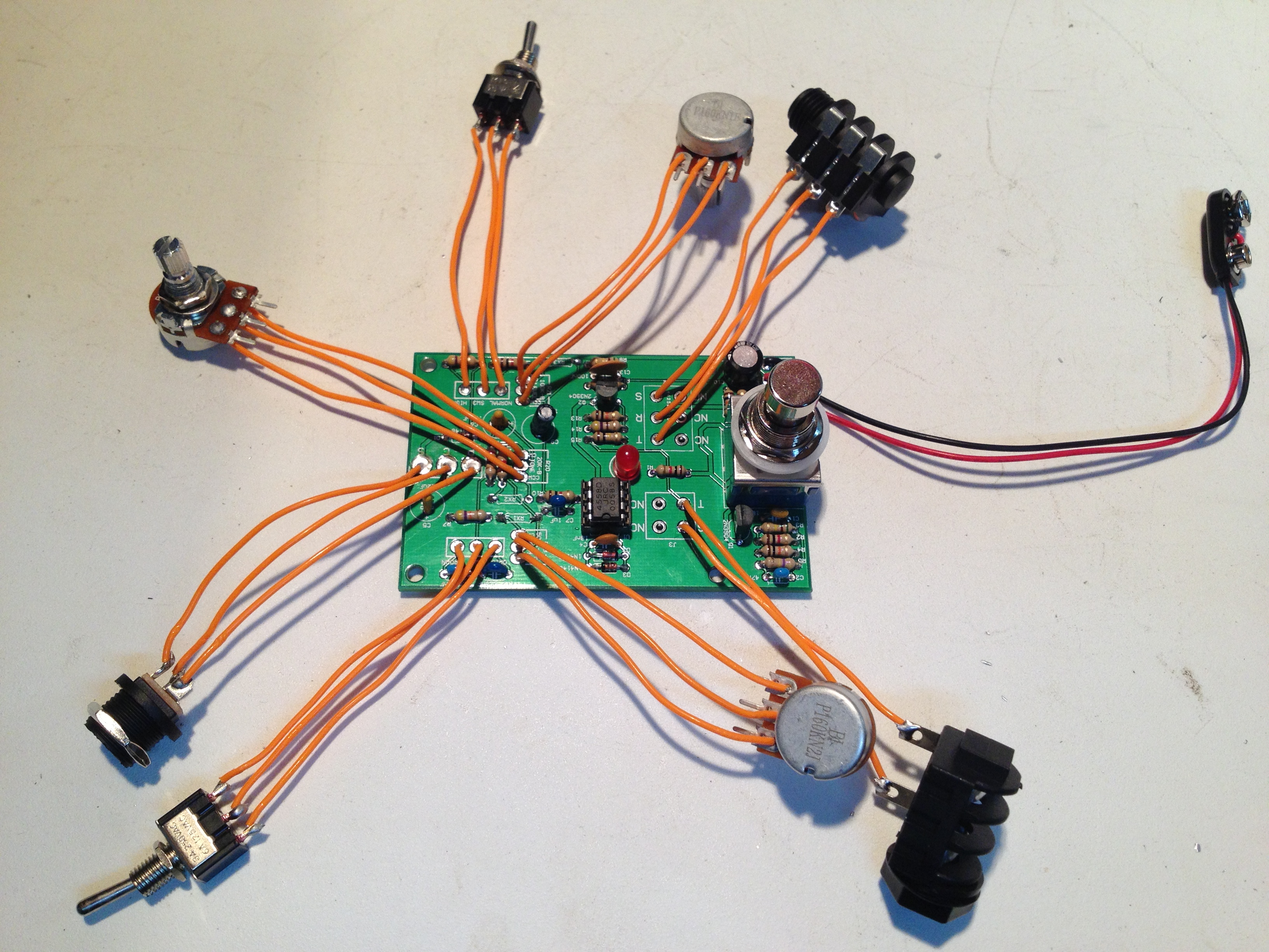
Install the potentiometers with the orientation shown above – with the adjustment knob facing you, the left pin should be connected to the the contact labeled ‘CCW’ and the right pin to ‘CW’. The SPDT switches can be installed in any orientation so long as the outer pins connect to the outer contacts and the center pin connects to the center contact. Connect the red lead of the 9v battery connector the ‘+’ contact, and the black lead to the ‘-‘ contact.
When installing the pot, some pots come with nubs near the shaft that may get in the way of installing the circuit into a case. Check for a nub and clip as necessary.

Don’t forget to cut the nubs on the potentiometers as neccesary.
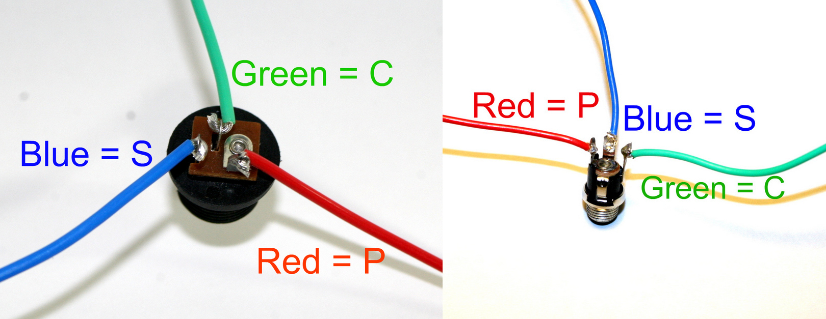
The ‘In’ Jack of the Tube Screamer circuit uses a 1/4″ stereo jack which turns off the power sources when nothing is plugged into it. When you plug a mono plug into the jack, the circuit receives power.
Stereo jacks have three solder lugs for the 3 different parts of the stereo signal: Tip, Ring, and Sleeve. On the PCB, they are identified as ‘T’, ‘R’, and ‘S’. Attach each solder lug on the jack to their respective PCB connection. Make sure to use the solder lugs as pictured above.
On the other side of the board is the ‘Out’ PCB connections. They are marked ‘T’ and ‘S’ for ‘Tip’ and ‘Sleeve’. Mono jacks only have these two connections, so they are easy to wire up.
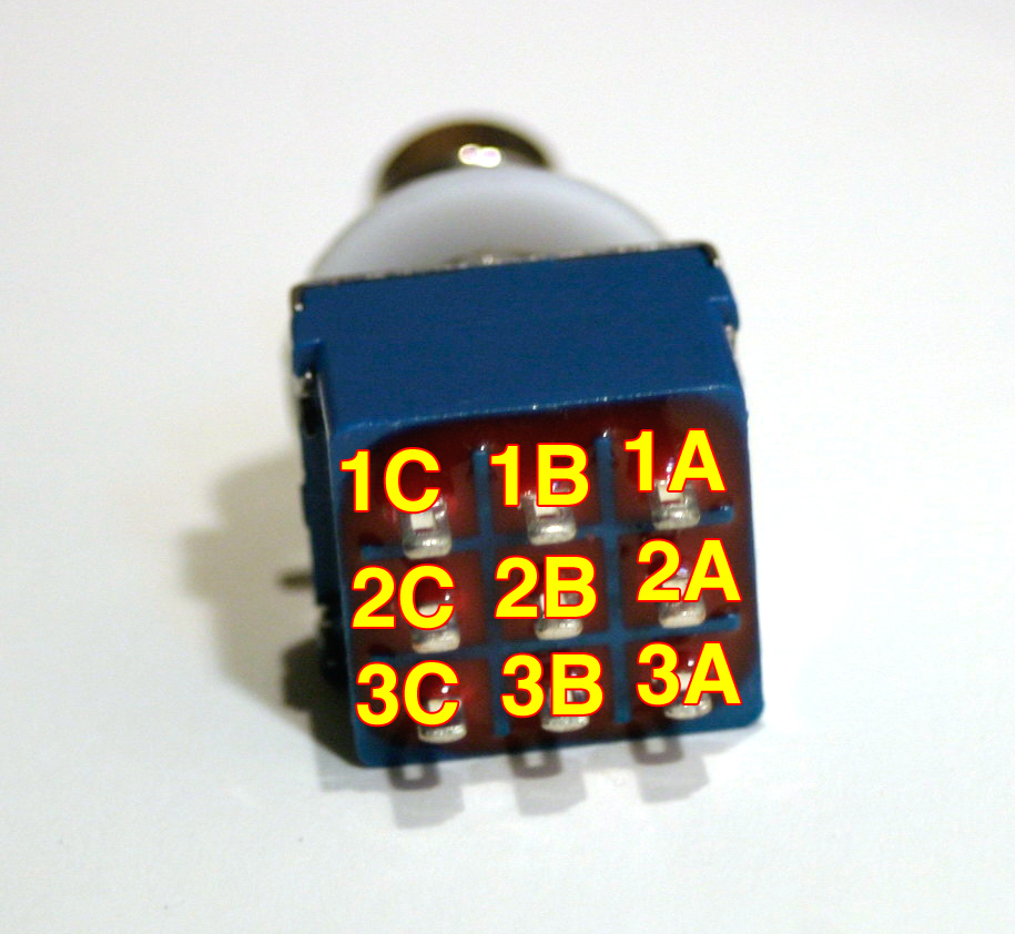
For the 3PDT stomp switch, match the silkscreen to the labeling shown above. You may wish to install the switch with wired leads if you are intending to mount the circuit within a case.
DC Jack Pinout
The DC Jack is fairly straightforward. Connect three wires to the DC Jack’s solder terminals and, using the picture above as a reference, connect them to the PCB at their respective through-holes. The center pin will be negative.
Once all of the wired components and stomp switch are connected, your circuit is complete and ready for testing.
Approximately how long do you cut your wires to? Just going through first build and wanted to check first. Measure twice cut once
Our wires for this unit are only a couple inches long. We don’t have exact measurements, we’ve just been cutting the wires for a very long time and just eyeball it.
Because the length of wire needed depends on the case and hole location, we suggest you drill out your case and then measure what you need to reach from the PCB to the case.
I love the tones I’m getting from the screamer but I’m getting a loud pop when I turn the footswitch on/off. I rewired it a 2nd time to make sure I got it right but still I get a loud pop. Any ideas? happens with battery or external power.
Hello Robin,
We’re currently trying to tackle the pop issue at the moment, and we have added notes to the Tube Screamer kits & such to note that there is a pop sound. We’re looking into a mod, and will announce it ASAP on the appropriate places if we can fix it.
All the best,
Synthrotek
hey there, i got the same loud pop when I turn the footswitch on/off. This its mi third tubescreamer and the same problem….please, let us know hor to fix this…may be a pull down resistor??? Regards
Hello there. We’re currently trying to tackle the pop issue at the moment, and we have added notes to the Tube Screamer kits & such to note that there is a pop sound. We’re looking into a mod, and will announce it ASAP on the appropriate places if we can fix it.
Thanks for the reply. Can’t wait for the mod fix. Keep us posted. Surely you have it figured out already.