


Important Links
Product Page
Store Page
Assembly Instructions
Bill of Materials
Capacitor and Resistor Lookup Guide
Please note:
There have been three different versions of the MST ’07 Buffered Multiple: 7HP, 8HP and 4HP. 4HP is the current version.
You can find assembly instructions for the 4HP version HERE.
The 7HP and 8HP versions can be found below.
MST ’07 Buffered Multiple Assembly Instructions (8HP)
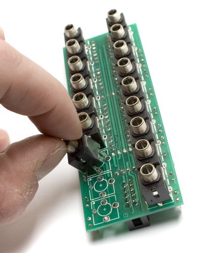
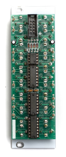
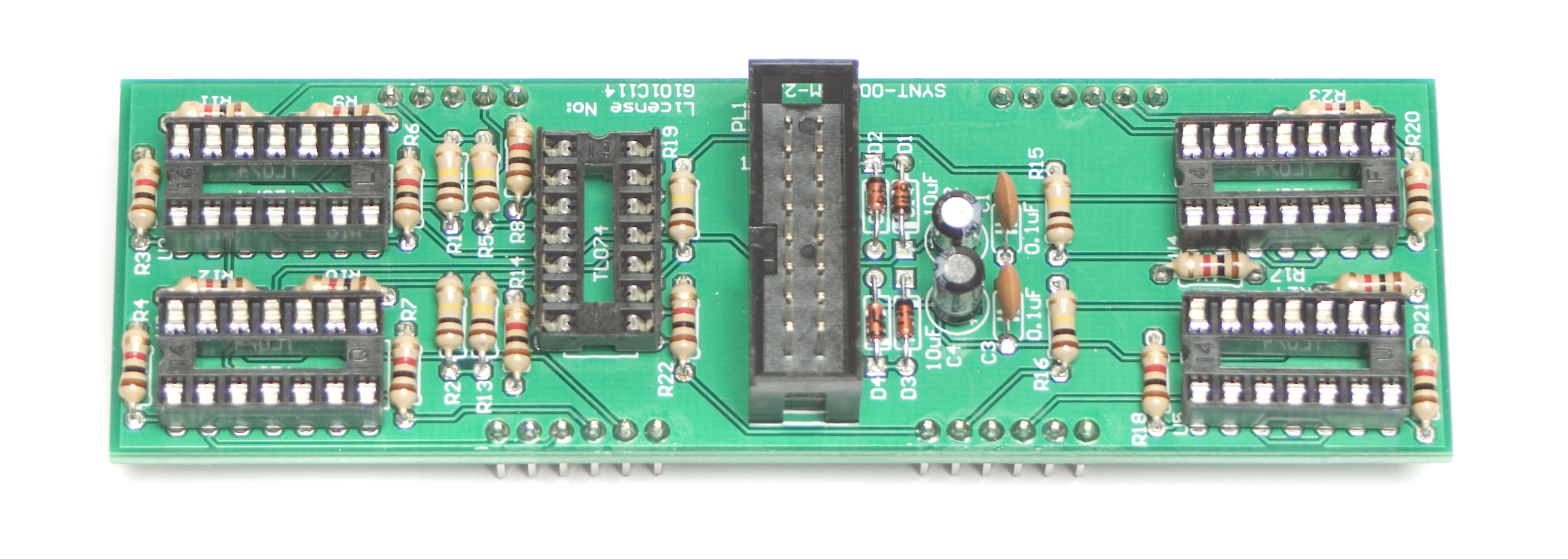
ATTENTION: We have recently updated our boards! Look closely at the following pictures to determine which version you have.
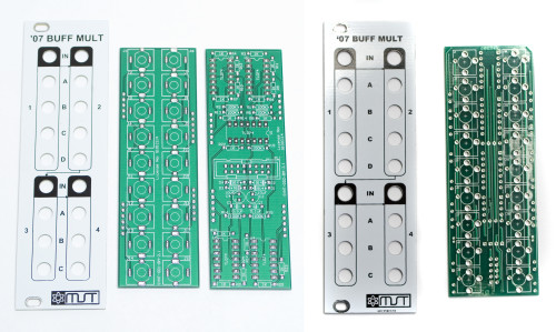
LEFT: Old 7hp Buff Mult with 2 PCBs RIGHT: New 8hp Buff Mult with 1 pcb
If you have the pcb/panel set pictured on the Left (7HP), please click Here for the assembly instructions.
MST ’07 Buffered Multiple Assembly Instructions
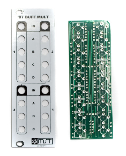
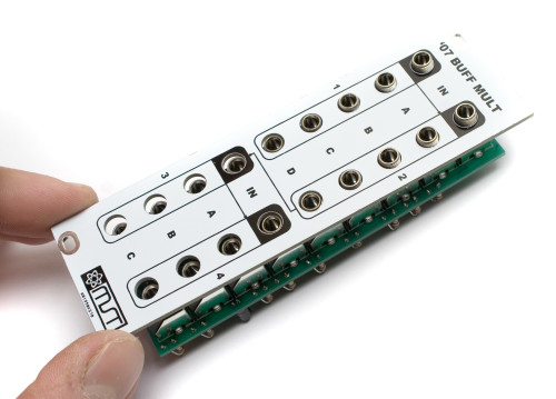
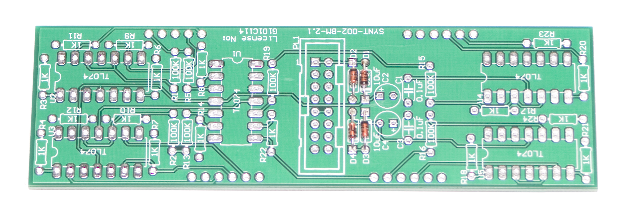
MST ’07 Buffered Multiple PCB/Panel
These are the instructions for the New version, with 1 pcb. If you have the older version, please click HERE for instructions.
Thank you for purchasing the MST ’07 Buffered Multiple Eurorack module kit! This is an intermediate build. If you feel like you can handle it please proceed! If not, get some help from a friend with experience or purchase a fully completed unit.
ATTN: Please follow the BOM and these instructions and don’t populate from the PCB alone. Also sometimes we cannot get the exact pictured components, so please look over your parts and check the codes first. Lets begin!
Diodes
Start with the diodes as shown below, then carefully flip over on a firm surface to solder, then clip your leads. Diodes are polarized components so you must match the black stripe on your diodes with the white stripe on the PCB silkscreen.
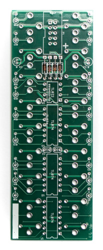
MST ’07 Buffered Multiple – Diodes
Ceramic Capacitors
Next up are the ceramic capacitors. These are non polar, so it doesn’t matter which way you orient them when populating. Insert them into their appropriate spots as per the BOM, and then flip your project over on a flat, hard surface and solder them in place, clipping the excess leads.
MST ’07 Buffered Multiple – Ceramic Caps
IC Sockets
Next up are the IC sockets. Pay close attention to the half moon looking notch in one side of the socket, and make sure it matches up with the same notch on the silkscreen. Once they are all populated, carefully flip your project over. A stiff card or another PCB could help with this process. Once you have it flipped over, start by soldering only one leg of each socket. Then check to make sure everything is flat and straight, then continue soldering the rest of the legs.
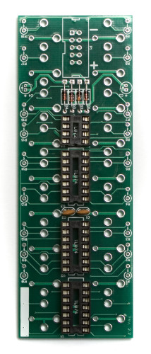
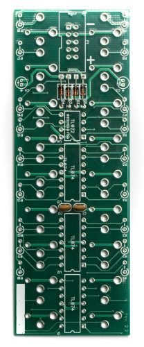
MST ’07 Buffered Multiple – IC Sockets
Electrolytic Capacitors
Next up are the electrolytic capacitors. These are polarized, so pay close attention to how they are oriented on the PCB. Insert the longer of the two legs into the solder pad that is closest to the ‘+’ symbol on the PCB. The stripe on the capacitor should be facing AWAY from the ‘+’ symbol. Once these guys are in, flip your project over, solder, and clip any excess leads.
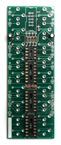
MST ’07 Buffered Multiple – Electrolytic Caps
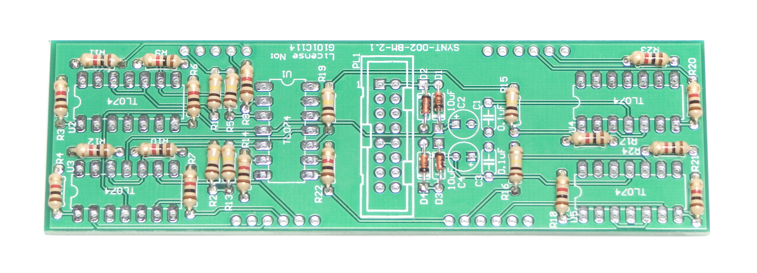
Resistors
Now we can populate the resistors. Insert each one into its appropriate spot, then carefully flip over your board, solder and clip the excess leads.
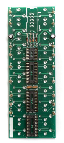
MST ’07 Buffered Multiple – Resistors
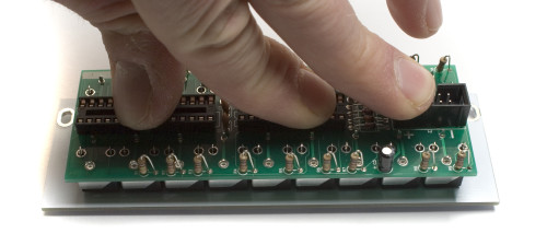
Power Header
Next, insert the 10 pin shrouded IDC header into the board, making sure to align the notch on the header, with the matching notch on the silkscreen. Then Flip the board over, and solder into place. You can use a similar tactic with this header as with the IC sockets to get it flat.
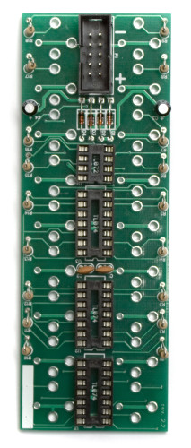
MST ’07 Buffered Multiple – Power Header
Jacks
Now you are ready to flip the project over, and start inserting jacks into the other side of the board. Insert all of the jacks as shown below, do not solder yet. Once you have the jacks in, place the front panel over the jacks, securing down with the supplied 3.5mm hex nuts.
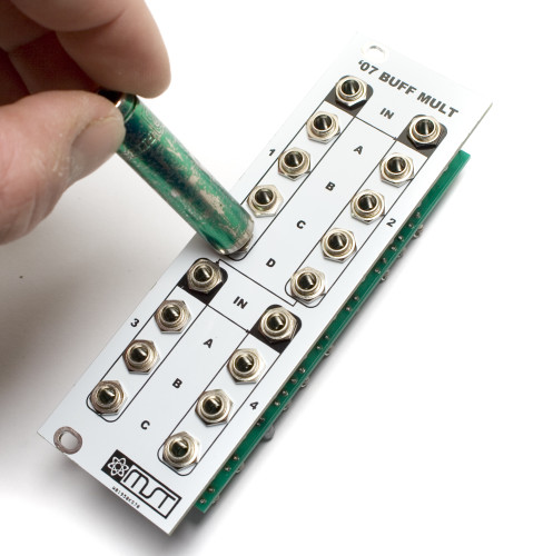
Note that when you put the panel on, it should be oriented so that the 10-pin power header on the PCB is facing the bottom side of the panel. The panel will fit the board upside down as well as right-side up, and if it’s oriented incorrectly, it won’t work.
Once the front panel is secured, flip the project over so it is resting on the jacks, and GENTLY push on the back so that the board is flat and straight.
When the panel and PCB are aligned and straight, you can solder up all the jacks.
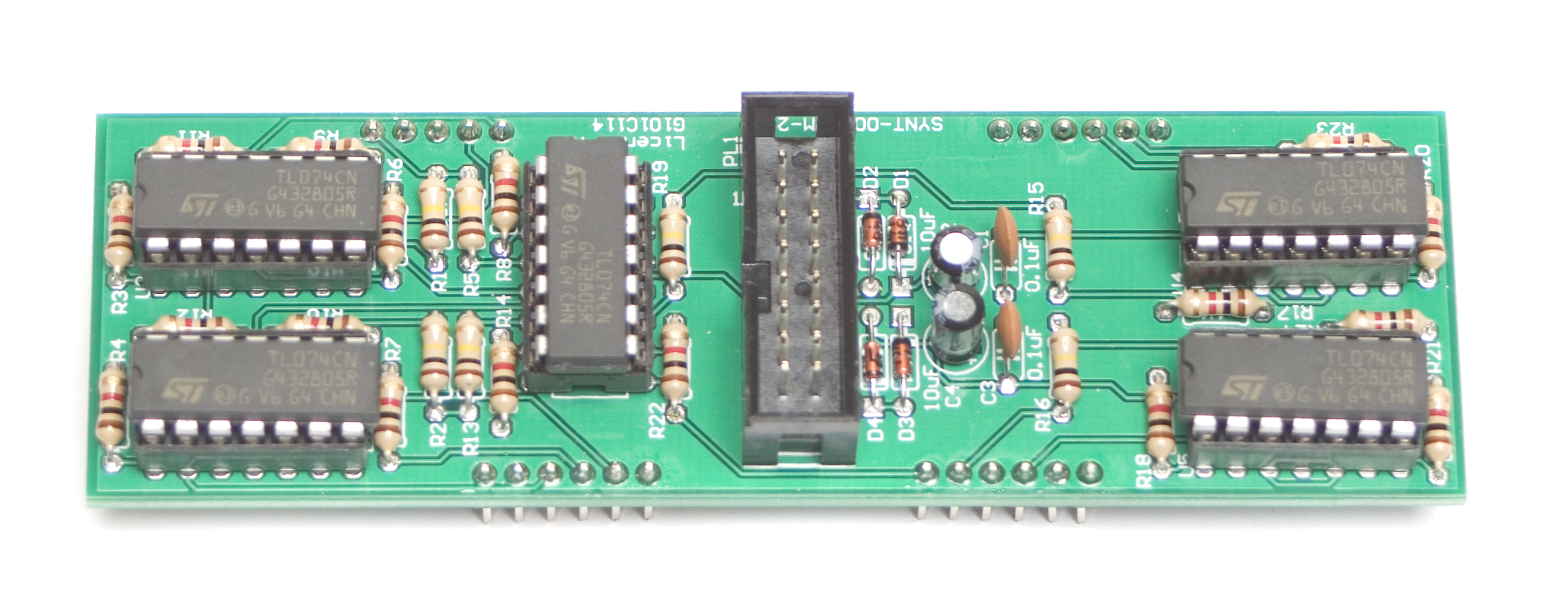
ICs
Next, carefully insert the ICs into their proper sockets. You may need to slightly bend the legs of the IC inward so that it will fit. When inserting, make sure to align the notch in the IC with the same notch on both the socket and the board. Failure to properly align ICs may damage the IC, or other components.
MST ’07 Buffered Multiple – ICs
Done
Congratulations! You’ve completed the MST ’07 Buffered Multiple!
TESTING PROCEDURE
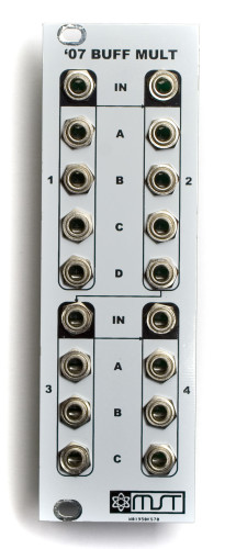
1 INPUT -> 14 OUTPUTS
Start by plugging in a CV signal from a sequencer or a MIDI to CV module into INPUT A (top left jack inside a white box). Since INPUT 1 (top left jack inside a black box) is normalled to INPUT 2 (top right jack inside a black box), INPUT 2 normalled to INPUT 3 (bottom left jack inside a black box), and INPUT 3 is normalled to INPUT 4 (bottom right jack inside a black box) you can test all available 14 outputs.
TESTING WITH 1 OSCILLATOR
Plug a cable into a 1V/O INPUT on an Oscillator and plug the other end of the cable into Channel 1’s A Output jack on the MST ’07 Buffered Multiple. Make sure that each of the 4 “Channel 1” OUTPUTS, the 4 “Channel 2” OUTPUTS, the 3 “Channel 3” OUTPUTS, and the 3 “Channel 4” OUTPUTS are all making precise copies of the INPUT 1 signal by monitoring your Oscillator’s OUTPUT.
TESTING WITH MORE THAN 1 OSCILLATOR
Plug a cable into a 1V/O INPUT on Oscillator #1 and plug the other end of the cable into Channel 1’s A Output on the MST ’07 Buffered Multiple. Plug a cable into a 1V/O INPUT on Oscillator #2 and plug the other end of the cable into Channel 1’s B Output.
From here it’s best to get both Oscillators in tune with each other so you can hear them both reacting the same way to the INPUT 1 signal. Make sure that each of the 4 “Channel 1” OUTPUTS, the 4 “Channel 2” OUTPUTS, the 3 “Channel 3” OUTPUTS, and the 3 “Channel 4” OUTPUTS are all making precise copies of the INPUT 1 signal by monitoring the OUTPUTS from both Oscillators #1 and #2.
1 INPUT -> 4 OUTPUTS
1 INPUT -> 4 OUTPUTS
1 INPUT -> 3 OUTPUTS
1 INPUT -> 3 OUTPUTS
Keep the INPUT 1 signal plugged in from the previous test as we’ll break the INPUT normalling by plugging in a CV signal from another sequencer or a MIDI to CV module into INPUT 2. Plug in another CV signal into INPUT 3, and plug the last CV signal into INPUT 4.
Plug a cable into a 1V/O INPUT on Oscillator #1 and plug the other end of the cable into Channel 1’s A Output on the MST ’07 Buffered Multiple. Plug a cable into Oscillator 1’s FM / MOD input and plug the other end of the cable into Channel 2’s A Output. Plug a cable into a 1V/O INPUT on Oscillator #2 and plug the other end of the cable into Channel 3’s A Output. Plug a cable into Oscillator 2’s FM / MOD input and plug the other end of the cable into Channel 4’s A Output.
Make sure that each of the 4 “Channel 1” OUTPUTS, the 4 “Channel 2” OUTPUTS, the 3 “Channel 3” OUTPUTS, and the 3 “Channel 4” OUTPUTS are all making precise copies of their respective input signals by monitoring the OUTPUTS from both Oscillators #1 and #2.
By now you should be able to confirm that all INPUTS and OUTPUTS are working correctly on the MST ’07 Buffered Multiple and that your unit is working correctly.
If you have any questions or need help debugging, please first refer to our troubleshooting guide BY CLICKING HERE. If this gets you nowhere, please contact us by email for support. Thank you again for purchasing your kit from Synthrotek!
Having trouble with your build? Check out the Troubleshooting Guide for some tips and tricks!
MST ’07 Buffered Multiple Assembly Instructions
These are the instructions for the older version, with 2 pcbs. If you have the newer version, please click HERE for instructions.
Thank you for purchasing the MST ’07 Buffered Multiple Eurorack module kit! This is an intermediate build. If you feel like you can handle it please proceed! If not, get some help from a friend with experience or purchase a fully completed unit.
ATTN: Please follow the BOM and these instructions and don’t populate from the PCB alone. Also sometimes we cannot get the exact pictured components, so please look over your parts and check the codes first. Lets begin!
DIODES
Start with the diodes as shown below, then turn over on a firm surface to solder, then clip your leads. Diodes are polarized components so you must match the black stripe on your diodes with the white stripe on the PCB silkscreen.
MST ’07 Buff Mult Diodes
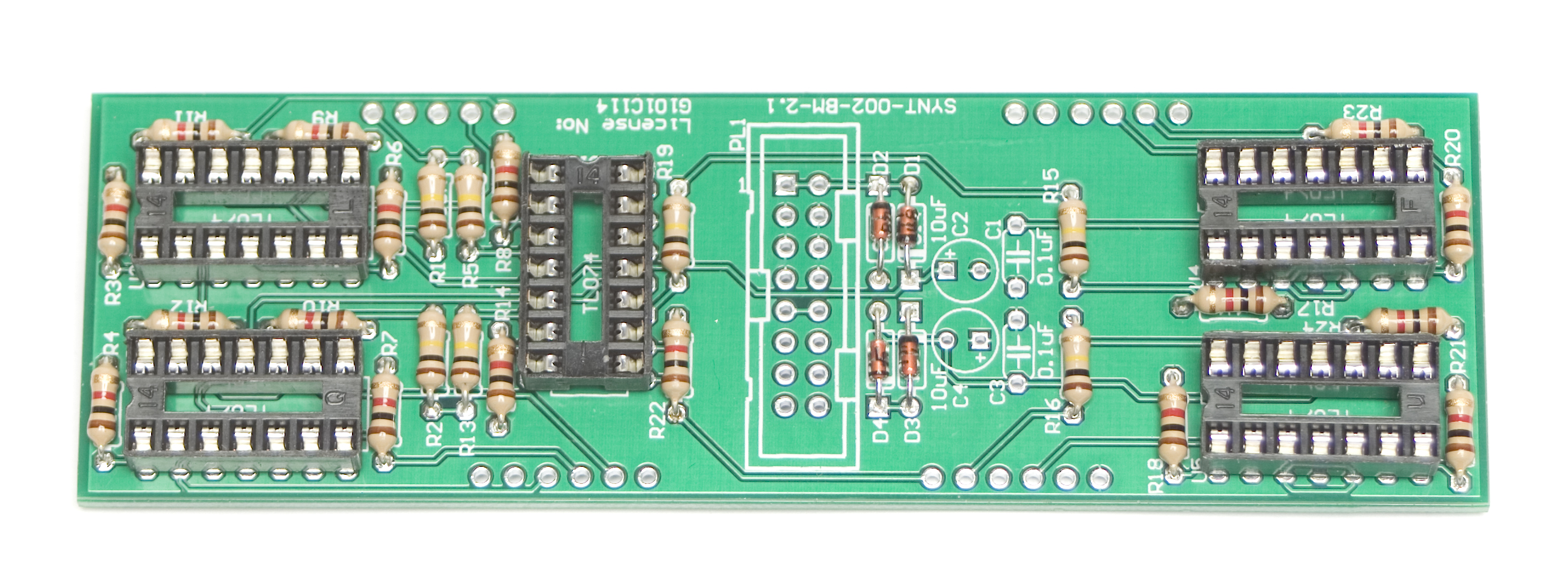
RESISTORS
Populate first, then turn over on a firm surface to solder and clip leads. Using a flat rigid card or another PCB can help hold the resistors in place as you turn the board over.
MST ’07 Buff Mult Resistors
IC SOCKETS
Place the IC Sockets by aligning the notch with the notch graphic on the PCB Silk Screen. Turn over on a flat surface and solder into place.
MST ’07 Buff Mult IC Socket
CAPACITORS
Add the capacitors as shown below. Make sure you orient the electrolytic capacitors in correctly. The longer lead needs to be inserted into the hole that has the “+” marking near it. Turn over to solder and clip leads.
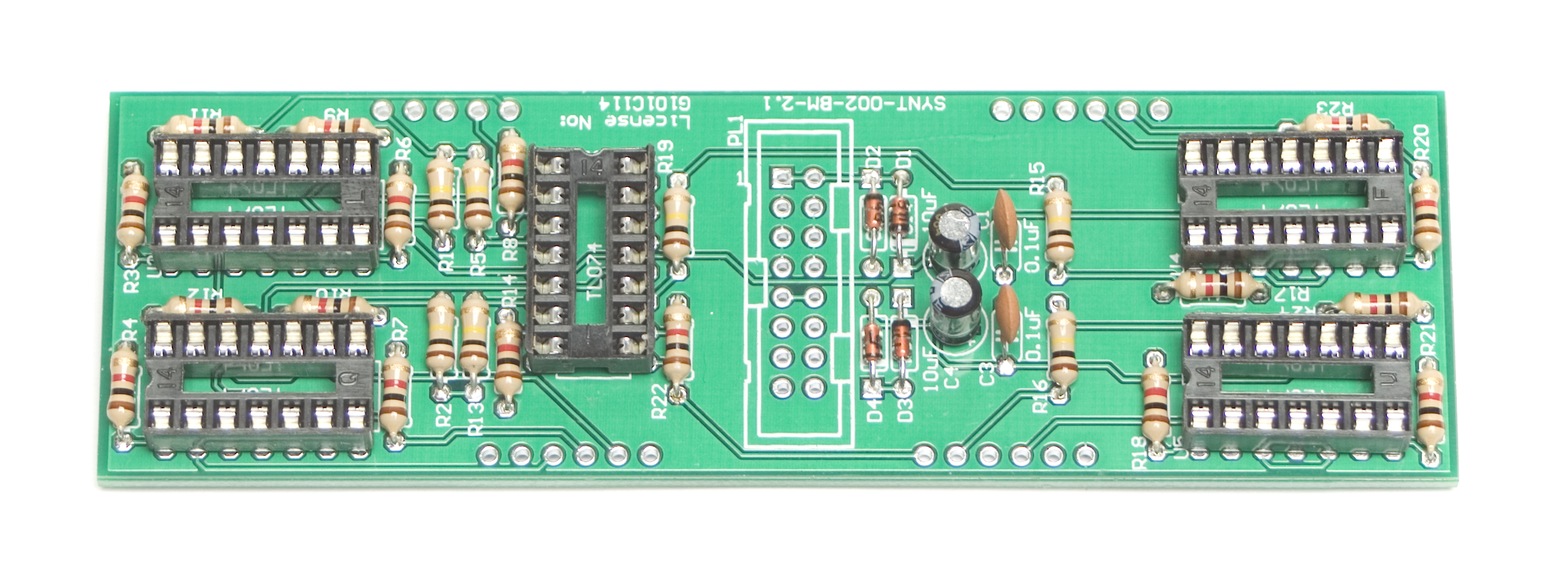
MST ’07 Buff Mult Capacitors
16 PIN EURORACK POWER CONNECTOR
Next add the 16-Pin Eurorack Power Connector in place by matching the key notch with the key indicator on the PCB silk screen. Turn over on a firm flat surface and carefully solder all of the pins.
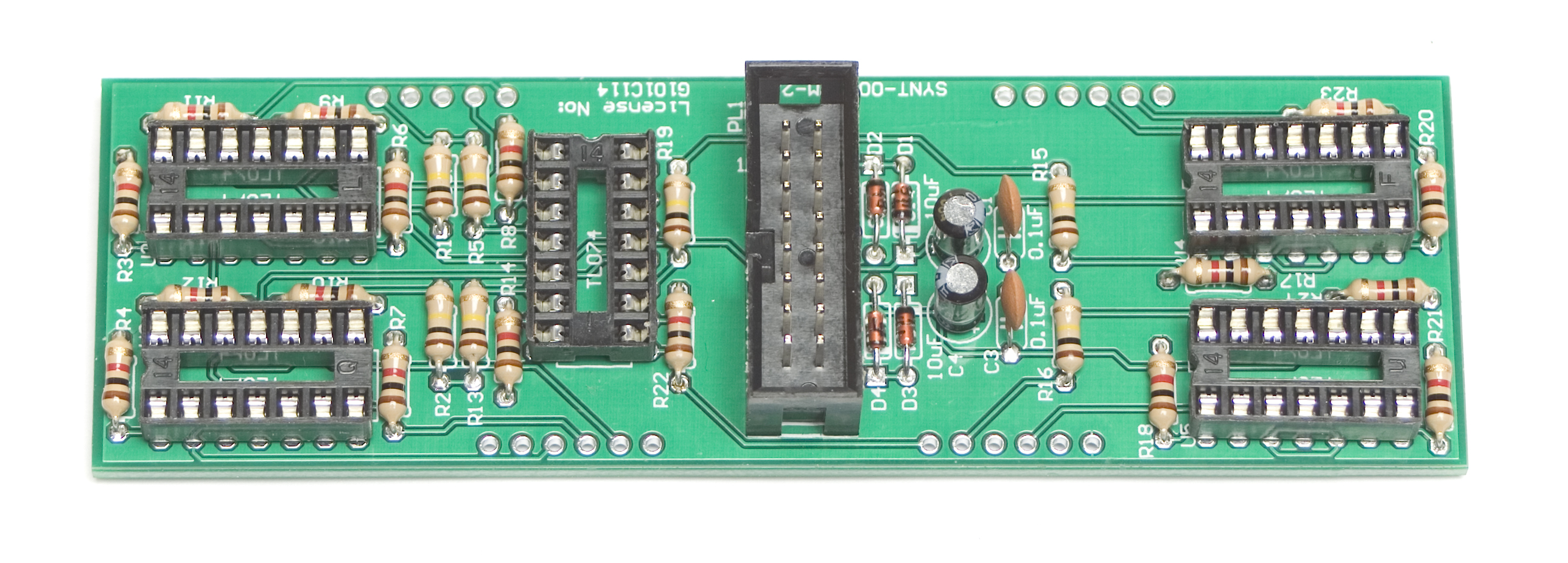
MST ’07 Buff Mult Power Connector
5 PIN MALE HEADERS
Now place the 5 pin male headers into their proper spots on the board. Then turn over to solder. There really isn’t an ‘easy’ way to do this, but some luck has been had by first SLIGHTLY filling the middle hole for the header. While holding the header to the board, apply LIGHT pressure and re-heat the solder. The header should slide down into place.
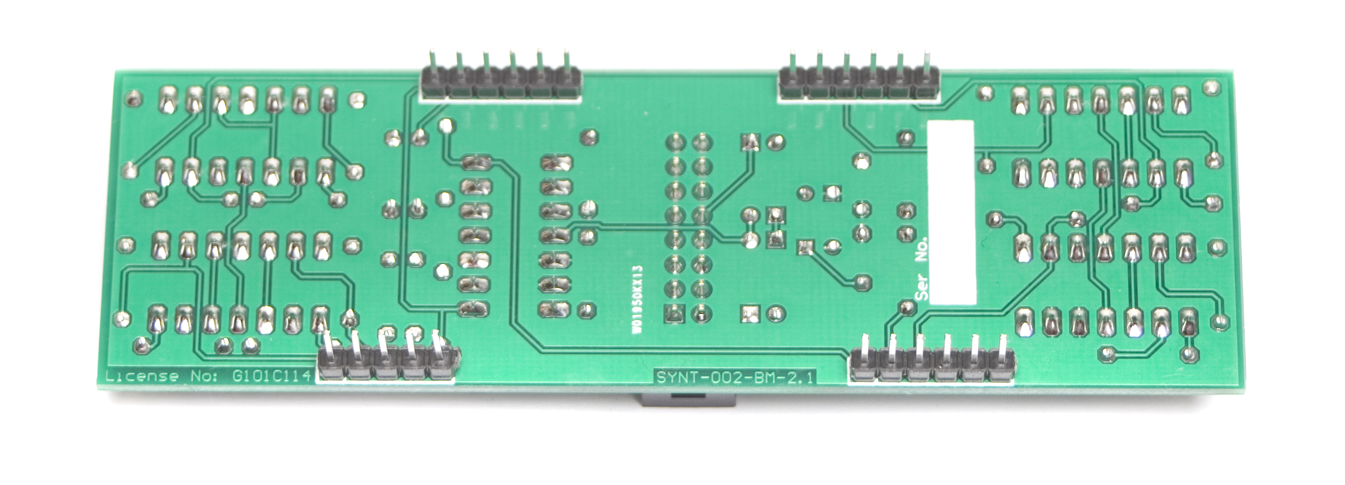
MST ’07 Buff Mult 5 Pin Headers
MST ’07 Buff Mult 5 Pin Headers Soldered
INSERT ICS
Next up, insert the ICs into their proper sockets by aligning the notches in the ICs with the notches on both the socket and the PCB silkscreen.
MST ’07 Buff Mult ICs
CONTROL BOARD HEADERS
Now it is time to start on the control board. First is the 5 pin female headers. Place the headers into the board and flip over on a flat surface and solder as shown below . Then clip the leads. If you’re having trouble, you can use the trick as described above (for the male headers) to help get them soldered down. Another pro tip for perfect alignment is to place the female headers (unsoldered) on the male headers already soldered to the logic board. Then align the control board PCB to the headers and make sure its nice and flat. Then solder the headers into the control board. The two boards can be removed now to continue on.
MST ’07 Buff Mult Control Board Headers
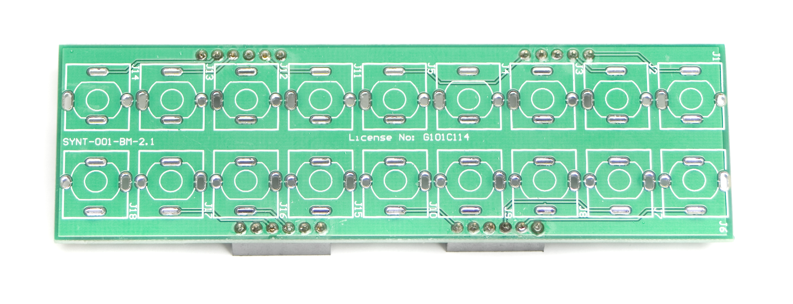
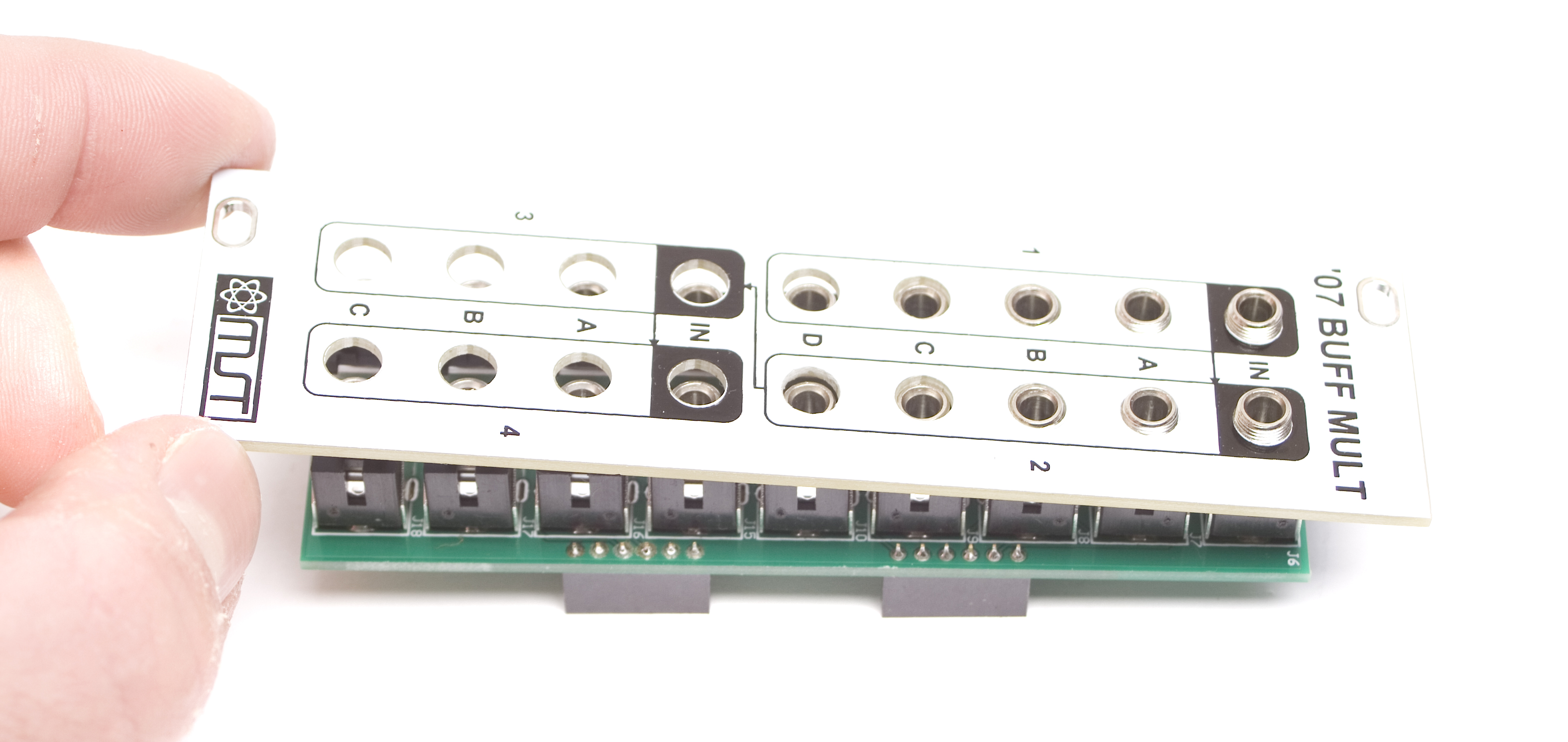
CONTROL PANEL JACKS
Now PLACE (do not solder yet!) the jacks in the circuit board as shown below. Make sure to remove ALL the nuts from your jacks before panel placement.
Please read through the whole process before starting!
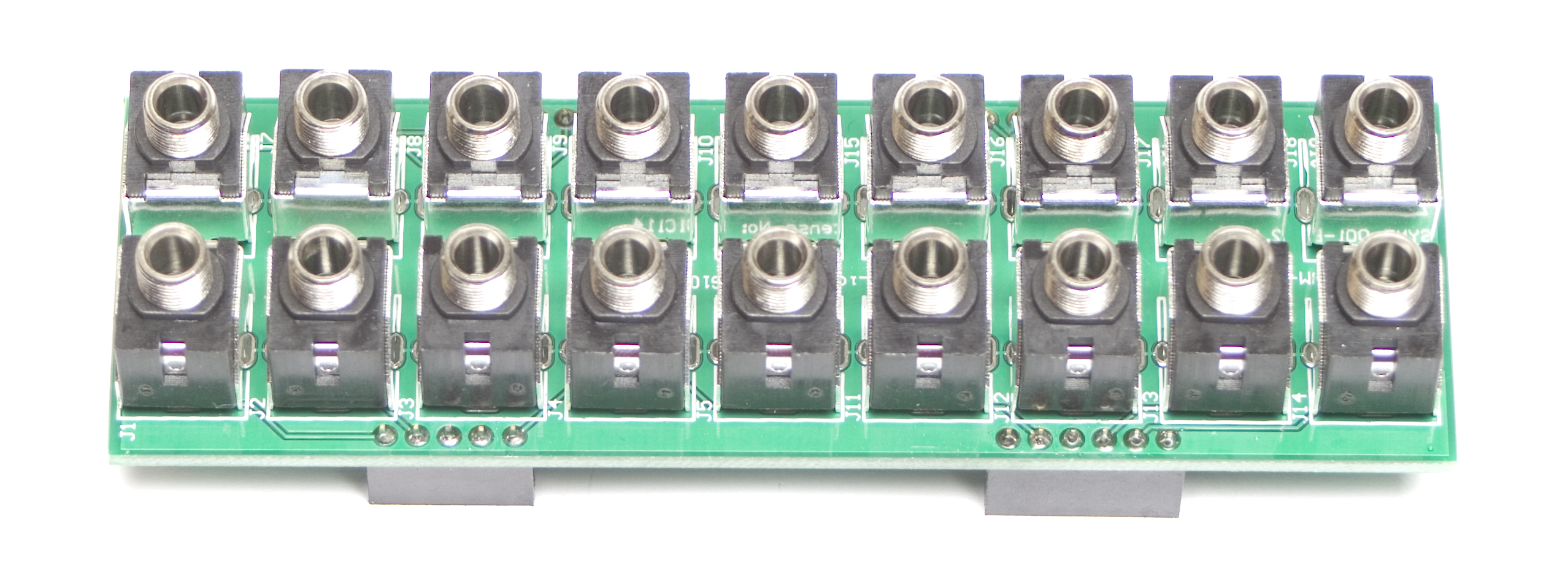
MST ’07 Buff Mult Jack Placement
Now place the panel over the pots, jacks, switches and LEDs.
MST ’07 Buff Mult Front Panel Placement
Fully tighten the nuts on the pots, jacks and switches. Be careful not to over-tighten!
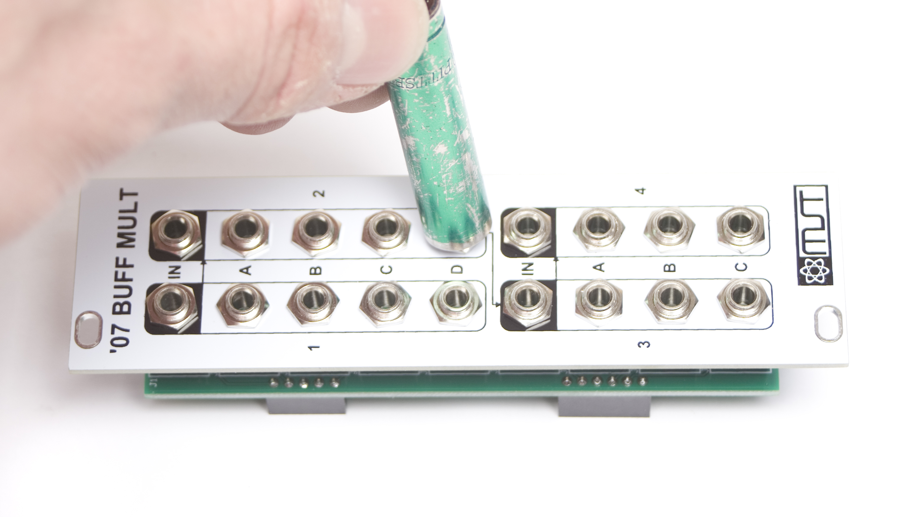
MST ’07 Buff Mult Jack Tightening
Now carefully turn over the assembly and solder all those jacks in place.
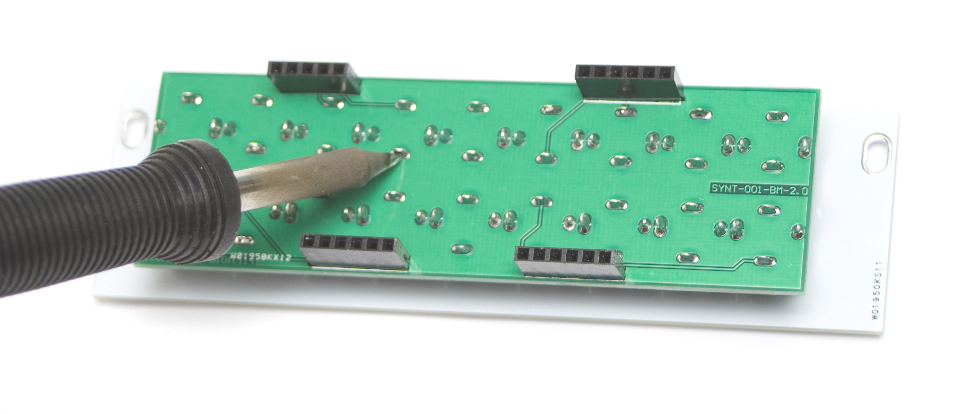
MST ’07 Buff Mult Jack Soldering
FINAL ASSEMBLY
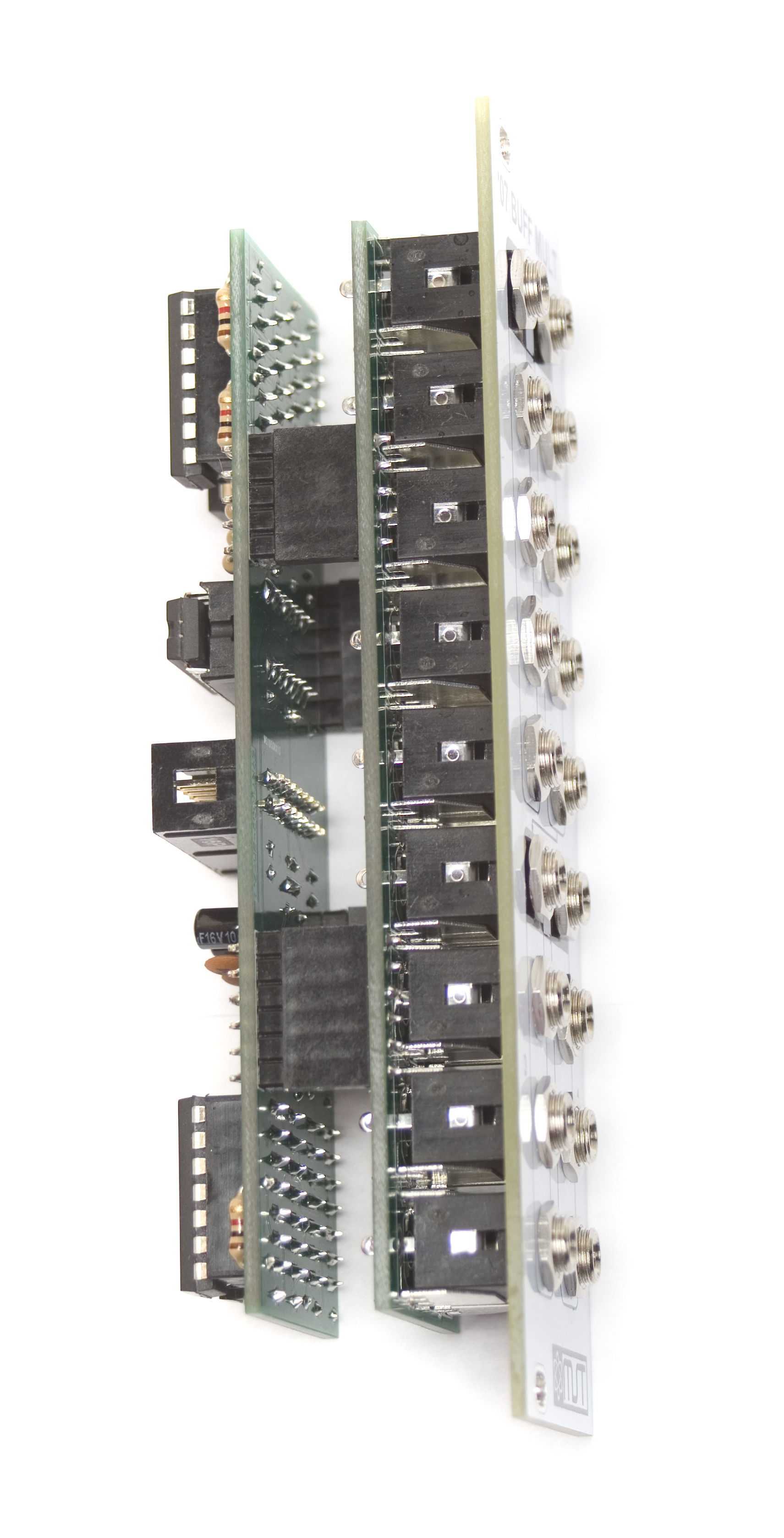
Now Carefully! connect the two boards together and you are ready for testing! Plug your power cable into your Eurorack power supply and test away.
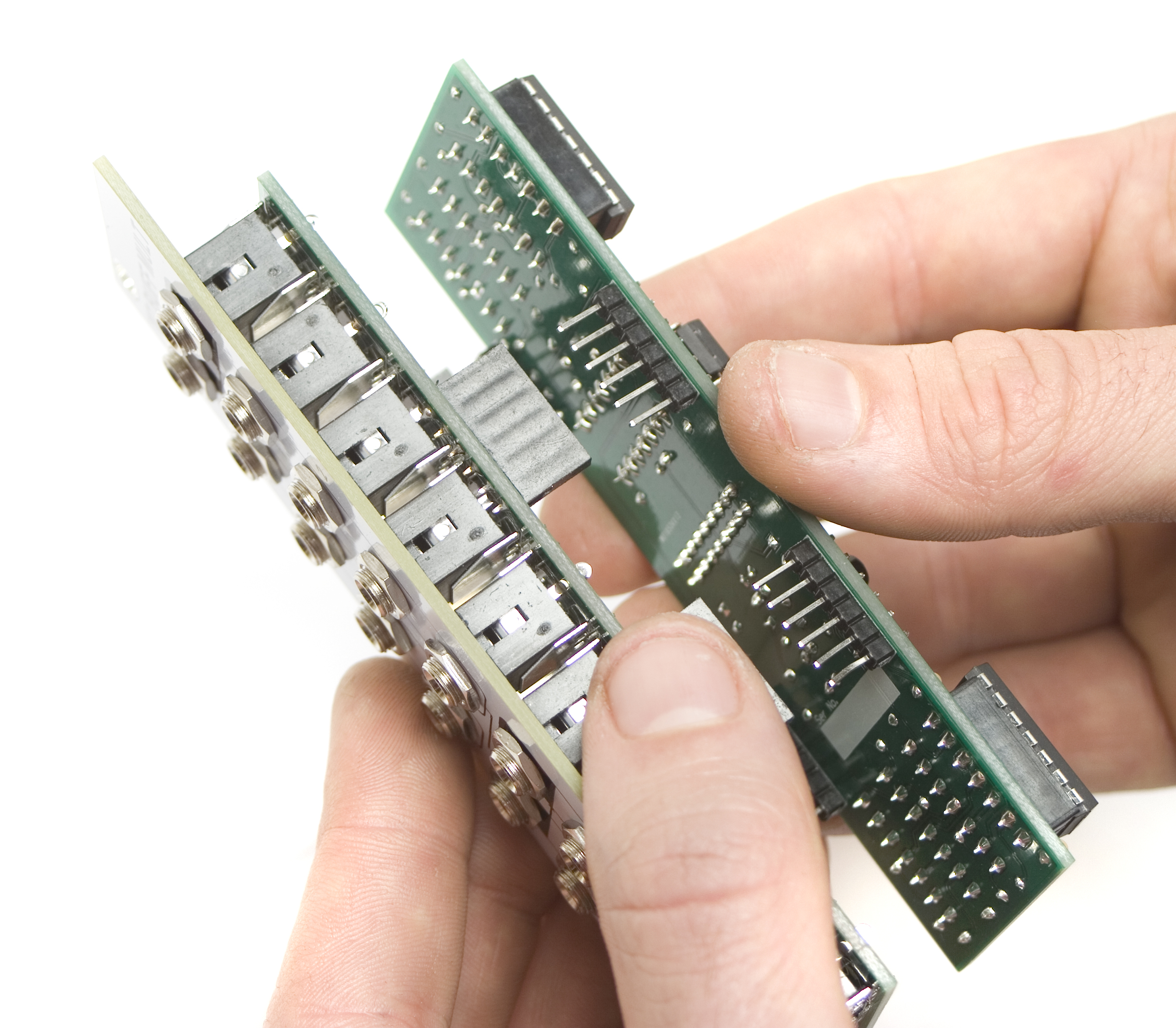
MST ’07 Buff Mult Board Connecting
COMPLETED UNIT
Now you have a completed and ready to roll MST AD/ASR Dual Envelope! Thank you for choosing Synthrotek!
MST ’07 Buff Mult Completed Unit!
TESTING PROCEDURE
1 INPUT -> 14 OUTPUTS
Start by plugging in a CV signal from a sequencer or a MIDI to CV module into INPUT A (top left jack inside a white box). Since INPUT 1 (top left jack inside a black box) is normalled to INPUT 2 (top right jack inside a black box), INPUT 2 normalled to INPUT 3 (bottom left jack inside a black box), and INPUT 3 is normalled to INPUT 4 (bottom right jack inside a black box) you can test all available 14 outputs.
TESTING WITH 1 OSCILLATOR
Plug a cable into a 1V/O INPUT on an Oscillator and plug the other end of the cable into Channel 1’s A Output jack on the MST ’07 Buffered Multiple. Make sure that each of the 4 “Channel 1” OUTPUTS, the 4 “Channel 2” OUTPUTS, the 3 “Channel 3” OUTPUTS, and the 3 “Channel 4” OUTPUTS are all making precise copies of the INPUT 1 signal by monitoring your Oscillator’s OUTPUT.
TESTING WITH MORE THAN 1 OSCILLATOR
Plug a cable into a 1V/O INPUT on Oscillator #1 and plug the other end of the cable into Channel 1’s A Output on the MST ’07 Buffered Multiple. Plug a cable into a 1V/O INPUT on Oscillator #2 and plug the other end of the cable into Channel 1’s B Output.
From here it’s best to get both Oscillators in tune with each other so you can hear them both reacting the same way to the INPUT 1 signal. Make sure that each of the 4 “Channel 1” OUTPUTS, the 4 “Channel 2” OUTPUTS, the 3 “Channel 3” OUTPUTS, and the 3 “Channel 4” OUTPUTS are all making precise copies of the INPUT 1 signal by monitoring the OUTPUTS from both Oscillators #1 and #2.
1 INPUT -> 4 OUTPUTS
1 INPUT -> 4 OUTPUTS
1 INPUT -> 3 OUTPUTS
1 INPUT -> 3 OUTPUTS
Keep the INPUT 1 signal plugged in from the previous test as we’ll break the INPUT normalling by plugging in a CV signal from another sequencer or a MIDI to CV module into INPUT 2. Plug in another CV signal into INPUT 3, and plug the last CV signal into INPUT 4.
Plug a cable into a 1V/O INPUT on Oscillator #1 and plug the other end of the cable into Channel 1’s A Output on the MST ’07 Buffered Multiple. Plug a cable into Oscillator 1’s FM / MOD input and plug the other end of the cable into Channel 2’s A Output. Plug a cable into a 1V/O INPUT on Oscillator #2 and plug the other end of the cable into Channel 3’s A Output. Plug a cable into Oscillator 2’s FM / MOD input and plug the other end of the cable into Channel 4’s A Output.
Make sure that each of the 4 “Channel 1” OUTPUTS, the 4 “Channel 2” OUTPUTS, the 3 “Channel 3” OUTPUTS, and the 3 “Channel 4” OUTPUTS are all making precise copies of their respective input signals by monitoring the OUTPUTS from both Oscillators #1 and #2.
By now you should be able to confirm that all INPUTS and OUTPUTS are working correctly on the MST ’07 Buffered Multiple and that your unit is working correctly.
If you have any questions or need help debugging, please first refer to our troubleshooting guide BY CLICKING HERE. If this gets you nowhere, please contact us by email for support. Thank you again for purchasing your kit from Synthrotek!