


Important Links
Product Page
Store Page
Assembly Instructions
Bill of Materials
Schematic
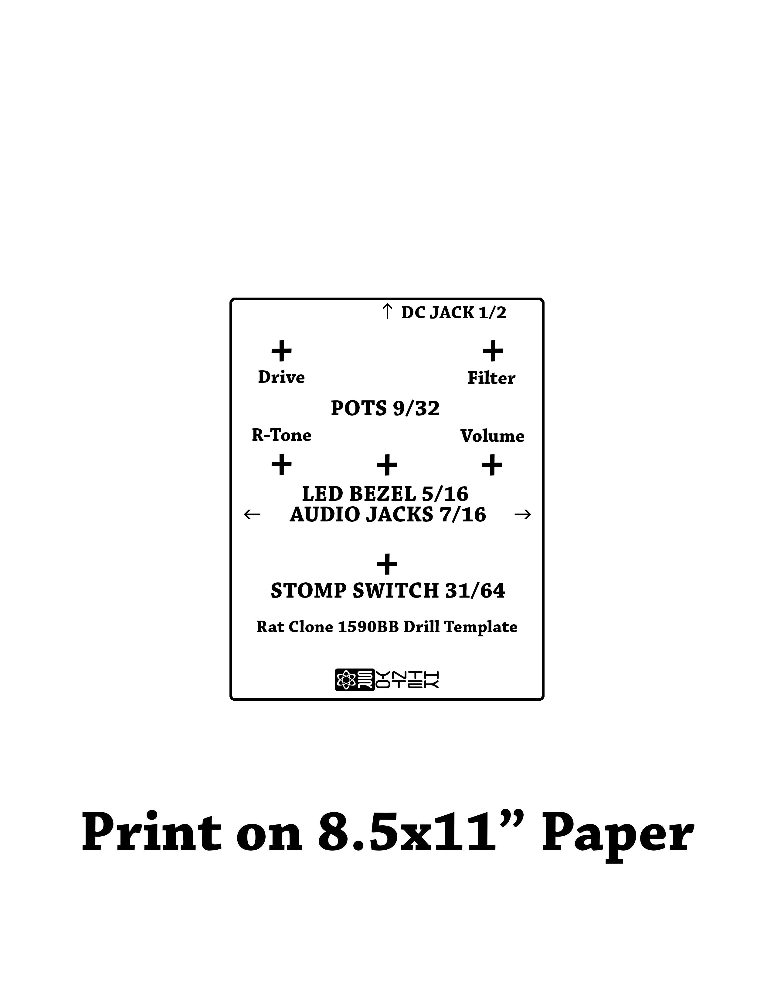
Drill Template
Capacitor and Resistor Lookup Guide
Below are the Assembly Instructions for the OLD RAT Clone with a square PCB.
If you bought the new version with a rectangular PCB, CLICK HERE.
Welcome to the Rat Clone Kit Instructions! It’s a great circuit and it’s an easy build, so let’s get started!
BOM Layout

Assembly
Attention: Changes may occur after the Assembly Instructions are created and the photos may not reflect those changes. Always use the BOM to verify the placement of components.
PCB Components
Resistors

Locate the silkscreen component identifiers for R1-R13. Insert each resistor into the correct through-holes and solder them to the board. Check out the BOM for help. Before you solder the IC socket make sure the half-circle notch on the front of the socket is lined up with the notch on the board.
Capacitors

Note the colored band on the electrolytic capacitors; this indicates the negative polarity lead of the capacitor. To further assist you, the PCB has a ‘+’ and a square through-hole for the positive lead and a circle through-hole for the negative lead.
For the smaller ceramic capacitors it does not matter which lead goes into which hole.
Diodes

There are five diodes and one LED. D1 is for the 1N4002 Diode (it’s black with a grey stripe.) Align the grey stripe with the stripe on the board. The stripe represents the negative lead. The geranium diodes are the larger clear ones that go above the Schottky diodes in the picture. Be sure to match up the negative stripes with the stripes on the board. They flip-flop back and forth from one diode to the next.
For the LED just make sure that the flat side (negative) is wired to the flat side of the symbol on the board.
Transistor/Piano Switch!

Align the flat side of the transistor with the flat side of the symbol on the board.
Insert the piano switch with the white switches facing the diodes.
Wired Components
Input/Output Jacks and Power Jacks

The ‘In’ Jack of the Rat Clone circuit uses a 1/4″ stereo jack which turns off the power sources when nothing is plugged into it. When you plug a mono plug into the jack, the circuit receives power.
Stereo jacks have three solder lugs for the 3 different parts of the stereo signal: Tip, Ring, and Sleeve. On the PCB, they are identified as ‘T’, ‘R’, and ‘S’. Attach each solder lug on the jack to their respective PCB connection. Make sure to use the solder lugs as pictured above.
On the other side of the board is the ‘Out’ PCB connections. They are marked ‘T’ and ‘S’ for ‘Tip’ and ‘Sleeve’. Mono jacks only have these two connections, so they are easy to wire up.

The 9V battery jack is easy to put onto the PCB. Take the red wire and insert it into the square through-hole with the silkscreened ‘+’. The black wire goes to the circle through-hole marked with a ‘-‘.
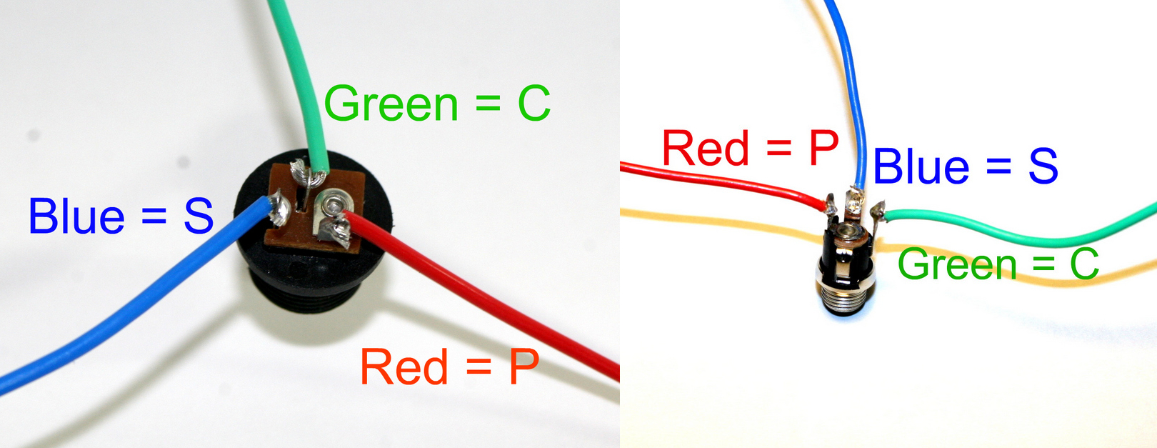
DC Jack Pinout
The DC Jack has three solder terminals that connect to the PCB. Use the picture above and the silkscreen on the PCB to place the wires correctly. The DC Jack allows you to power your circuit with a wall wart and disconnects the 9V battery from the circuit, saving money on expensive batteries.
NOTE: please remember to use a 9 volt center negative power supply. Using the incorrect power supply polarity will damage your circuit.
If you do not want to install the 9V DC jack and only install the 9V battery clip you will have to short the S and C pins for the 9V DC Jack like shown in the picture below*.
* Your PCB may not look exactly like the photo, that is ok. What is important is that you short the same pins as shown in the photo.
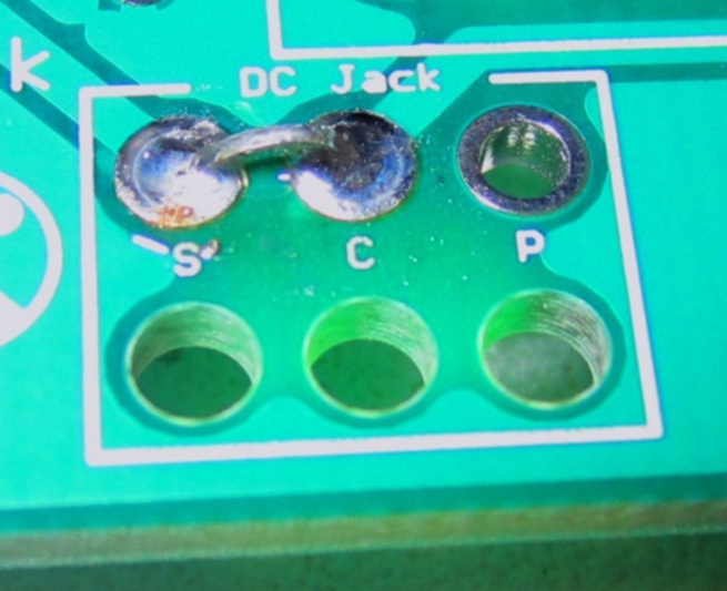
Short these contacts to get the circuit to work without the 9V DC Jack
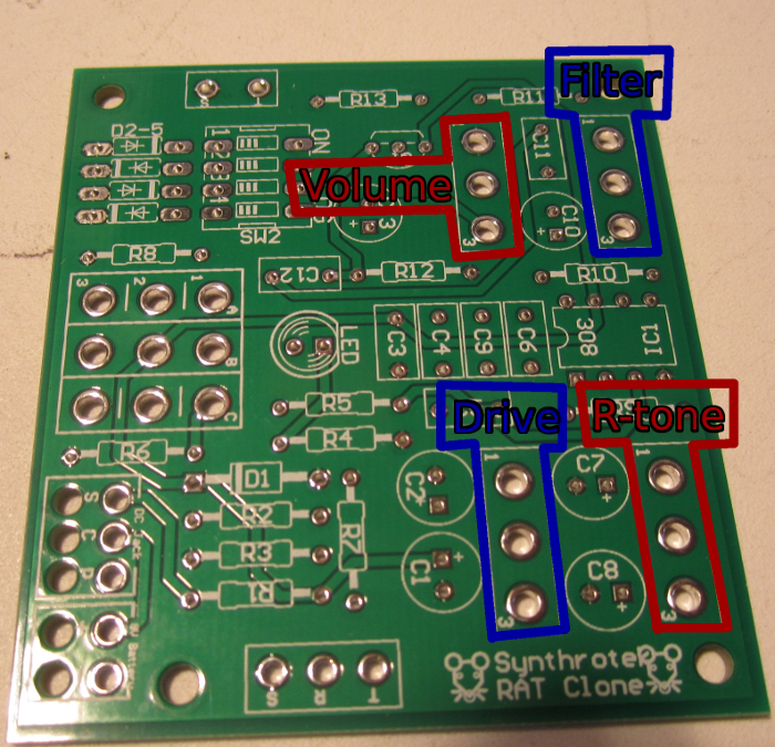
Potentiometers

Wire the pots as shown in the picture above.
We suggest soldering wires to the potentiometers before attaching them to the PCB. Having to de-solder a too-short wire from the PCB is an extra step that can be avoided. As always, use more wire than you think you will need; wire can always be cut.
Check out the pictures below for more help. There are small numbers on the board to identify placement.

When installing the pot, some pots come with nubs near the shaft that may get in the way of installing the circuit into a case. Check for a nub and clip as necessary.

Don’t forget to cut the nubs on the potentiometers as neccesary.
Stomp Switch

Line up the number code from the switch to the board exactly how it is labeled in the picture (above and below.)
Make sure the flat blue side of the stomp switch is facing up when comparing it to the picture below.


Congratulations, that’s the end of the instructions for the Rat Clone circuit! If everything is wired/connected properly, you should have a fully functional distortion pedal. Remember to adjust the piano switch to get the sound you want from your new pedal and have fun!
hey the bom page is down! id love to finish putting together my kit, but with half the instructions missing its a bit difficult
Let me know if this lonk helps, it is working here:
http://www.synthrotek.com/kit-assembly-instructions-2/
Can I use a couple toggle switches to adjust the piano switch outside the enclosure? Love the idea of having the tone options on a knob/toggle outside the enclosure with the volume etc…
Totally, I made a build exactly like this and it worked great!
Steve! Talk to me… How did you do this? Roughly?
Wire in 4 spdt toggle switches in between each via (holes on the PCB) across from each other. Does this help?
Does this pedal require everything to be installed in a metal encasing in order for it to power up and work?
No, you do not need to install this into a case for it to work. Are you having issues?
Hey. Thanks. Yeah I’m getting normal guitar sound when the pedal is off but then nothing when I switch the pedal on, not even a buzz. I’ve checked the battery and I’ve tried a different switch that was working in another pedal. I’ve also checked over the board for any dodgy solders or connections but it all seems ok. Have u guys got any tips for troubleshooting or good websites that could help. I’ve also checked the resistors and they are all normal. I’m not sure how to check the other components though. Any help would be much appreciated.
@Dazza I don’t know if you have figured out what’s going on with your pedal since its been so long, but I just finished mine and had the same thing happen. My problem was that lugs 1 and 3 where switch on the pots. Just make sure that all three lugs are wired right to the PCB. My problem now though is that there is a pretty big lack of high end in this pedal. Anyone else have the same problem? Or is this pedal just lacking high to begin with?
Hi Jordan, yes, the pot is switched, we are going to be fixing that soon. Sorry for the hassle there. I have never noticed a lack of high end. Audio sample?
@Steve Harmon
I figured it out. One of the pots was dirty or got some solder on the inner contacts. I switched out all the pots and all is well now. I was going to switch the pots anyway so I could use the knobs I had for this build.
Hey. I just finished the build and starting running some tests. The only problems i seem to be having is that there’s a loud buzz. i don’t know where its coming from and it sounds as if something is not grounded. Maybe theres a solution. Thanks!
Hi Angel,
It shouldn’t have a buzzing sound. We have seen before poor solder joints sometimes cause buzzing sounds. I would check your solder joints and see if you can’t touch any up that don’t look their best. Here is a quick little guide on common solder joint issues and repair methods: http://learn.adafruit.com/adafruit-guide-excellent-soldering/common-problems
Hi guys!
First of all, I’d like to say that just received and finished (almost) the your Rat build and sounds really good!
Just a few questions:
-I had an issue with the small capacitors as 3 of them weren’t labeled and couldn’t decode them, but I guess I figured it out with the help of the elimination process. I can send a photo so u can tell me if something is wrong.
-I’m getting a weird, high pitched noise when the R-tone is on max and the pitch modulates as i turn down the Gain knob (at around 3-5), maybe it’s because of a wrongly placed capacitor? I’ll re-check the joints as well.
All in all the build works really well with the TS clone and a good valve amp 🙂
One more question: You said earlier that it is possible to replace the piano switch with 4 SPDT switches. I have a couple of mini SPST switches lying around and thought I’ll use them for the build. I guess it should work as the Piano switch itself is basically 4 SPST switches together as I read on the BOM?
Keep rockin!
LP
Hi LP,
Were the unlabeled capacitors small and blue? If so, you just need to hold them under a light. On one side there is a gray stamp of the capacitor’s value that is hard to see under low light.
The weird noise you are experiencing should not be occurring. I would assume that this issue is coming from a misplaced capacitor.
And yes, you can replace the Piano Switch with four SPST switches. The rectangles inside of the silkscreen box for the piano switch indicate the orientation of how each switch is hooked up.
I just put one of these together and it sounds amazing.
One thing I am confused about is the filter pot. Wiring it as specified, it seemed to work in reverse (i.e. turning it up reduced the volume). So I wired it the other way round and it now works the ‘right way’ but all it seems to do is act as a second volume pot. Did I miss something?
Also, the numbers for the diodes on the BOM don’t match up with what’s on the board. Not a problem, but needs correcting.
John, on the rat, the filter traditionally works where clockwise is an increase in the low-pass filter. I know many filters can work the other way, but on the rat, that is the way the initial design was made in order to diminish some of the high-end.
Yes, you are right! The BOM is always correct, we will fix this on a subsequent version.
Thanks for rocking this!
hay there, i just finished building on of these for a charity auction, and its not working! LED is dim and there is no output at all when engaged. anyone know where to start trouble shooting? (im also auctioning a built PT2399 delay of yours with this unit for the charity)
Hello Eric,
Sorry to hear about this. I suggest checking out our troubleshooting guide : http://www.synthrotek.com/tech/troubleshooting-your-build/
Hope this helps, and feel free to contact us via email with pictures of your build if you get stuck.
-Synthrotek
@Steve Harmon
Thanks, Steve. i’ve just ordered another one as I want to do one with external diode switches. I would also like to eliminate the filter pot as I can’t see any circumstances where I would want to use it. How should I wire up to miss out that pot?
@John Morgan-Evans
Presumably you would just short pads 2 & 3?
Hello, I just got my kit in the mail and really looking forward to starting, but I was wondering… does the enclosure have to be drilled and setup horizontally(wider left to right than tall)? Can the pedal be setup in the enclosure in the vertical (taller than width) way? I hope that makes sense. I’m a fan of this pedal size for building and footprint purposes, but if this can only assemble and fit together with the drilling template provided, I just want to make sure. Let me know. Thank you.
Hello Matt. We use the Wired RAT Clone to build the “Ratatak.” It’s setup horizontally, like so : http://www.synthrotek.com/synthrotek-ratatak-proco-rat-boutique-pedal-clone-with-r-tone-mod/
That’s a fully wired product, but you can get some PCB Mount 3PDT Latching Stompswitches from here and seat them into the PCB: http://www.bitcheslovemyswitches.com/
Hope this helps!
Right on, but does it HAVE to be set up horizontally? has/could it work vertically?
It can be setup either way, since it’s wired. Just plan your layout accordingly and you should be good to go. There’s plenty of space in that enclosure.
When I hooked this up to my amp the led lit up for a few seconds then went off, I wasn’t getting any sound but I realized i had forgotten to plug the IC into the socket. I plugged in the chip but I still have no sound or led.
Hey Todd. I’m guessing that you probably might have fried an electrolytic capacitor, or maybe the JFET (2N5458) got fried? I’m not sure what problem would arise when turning on the unit without a LM308. Give our Troubleshooting page a look over and see if there’s something that might be able to help you out : http://www.synthrotek.com/tech/troubleshooting-your-build/
How would I go about testing the caps and the JFET?
Sorry for the triple-comment, but I just realized I am a dumb idiot and put the battery jack backwards. Swapped them and it works now! Doesn’t sound like anything is fried as far as I can tell :+)
Oh no! Glad to hear that it works after swapping the wires on the jack. Enjoy the RAT, Ted!
Just to clarify for other people troubleshooting, I was having the same problem as Todd (forgot to plug in IC), and it turned out to be fine after I found my battery jack problem.
One more question though – is there an easy way to make this sound better on bass?
Would an extra cap at input work?
From what I read online (I am not a bass player), the Rat is supposed to sound good with bass. Saw this:http://www.talkbass.com/threads/is-the-rat-pedal-good-for-bass.501770/
There is this Ruetz Mod, that some folks like.
Sorry I dont have more!
this picture of the footswitch is terrible, you cant figure where to start marking the spots. It should have a reference in the actual piace.
Marking the spots? I’m a little confused, could you be more descriptive? There is a picture of the footswitch vias and the switch itself with corresponding letter/number codes on each.
The footswitch has two flat blue sides, identical, doing it wrong inverts its position (mirrored). But i figure that out.