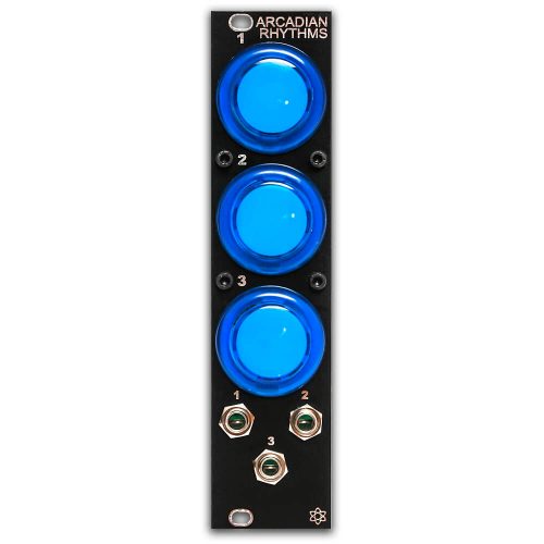
Thank you for purchasing the Synthrotek Arcadian Rhythms Eurorack kit. This is pretty easy build but there are some important steps that you MUST follow.
Please build according to the BOM, and not these instructions or the pictures alone. Some components may have changed since these were written, or we may not be able to get the same components that are in the pictures.
Let’s begin!
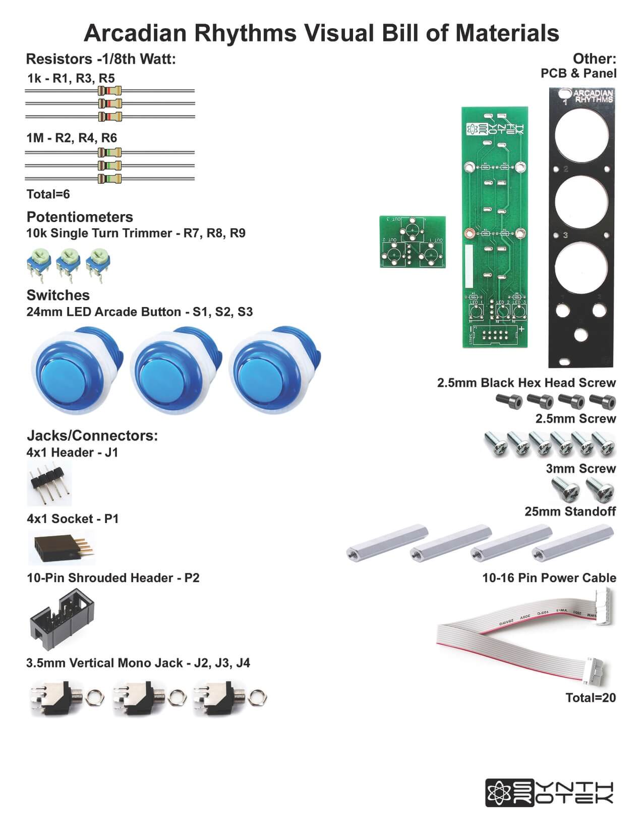
For a Bill of Materials with the part numbers included, click here.
Resistors & 4×1 Header
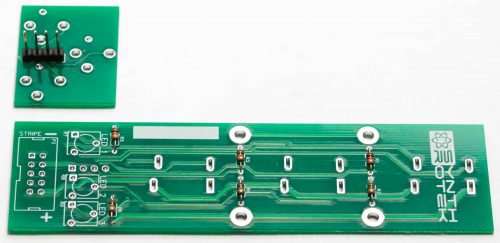
Take the green PCB and carefully break off the smaller portion from the larger.
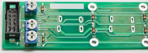
Take the 6 resistors and place them into the panel as shown below. Resistors are not polarized, so you can place them either way. Turn over to solder then clip excess leads. KEEP YOUR RESISTOR CLIPPINGS, THEY WILL BE USED LATER!
Solder in the 4×1 header to rear of the small PCB
Trimmer Resistors and Jacks
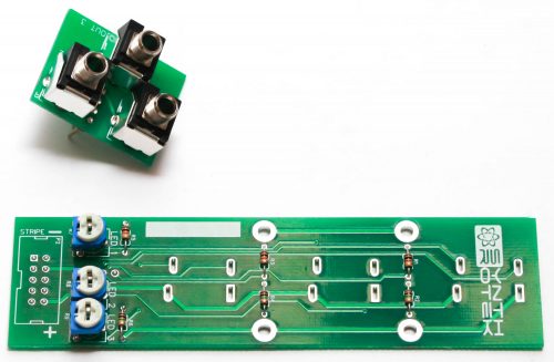
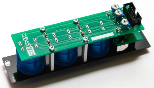
Carefully solder in the three jacks as show below and then place the three trimmer resistors into the large PCB. Carefully turn the PCB over and solder in place.
Solder in the three jacks into the small board as shown below.
10 Pin Power Header
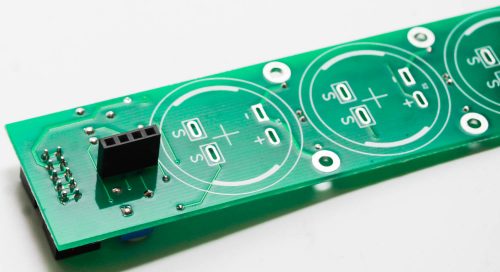
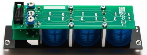
Next, align the notch on the 10 pin Eurorack power connector with the notch in the silkscreen, as shown below. Flip the board over and solder everything in place.
4×1 Socket
Place the 4×1 Pin socket into the PCB, carefully turn over and solder into place as shown below.
Long Pin Standoffs
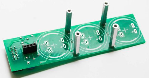
Screw in the 4 long pin standoffs as shown below
Buttons and Panel Connection
First, connect the small PCB with the jacks to the panel and hand-tighten the nuts.
Next, marry the panel and large PCB and secure the panel to the standoffs with the black hex screws.
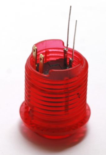
NOTE! Some arcade buttons have one set of leads that are SHORTER than the others. If you have these kind (as shown below), you will have to attach your excess resistor lead clippings to the shorter leads so that they will fit through the PCB. If all the leads on the button can be inserted directly into the PCB, disregard this part.
You can now place the arcade buttons into the project as shown below. The arcade buttons will only fit into the PCB pads ONE WAY! Make sure you align the solder pads with the orientation with the leads of the arcade buttons!
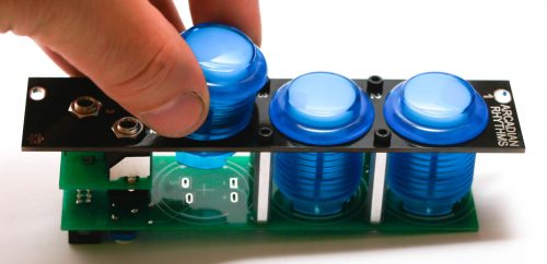
After you have the arcade button pins aligned with the solder pads, CAREFULLY turn the project over. Take a good look at the solder pads to make sure that the arcade button pins (or resistor clippings) are through the holes.
Finally, solder the arcade button leads into place. Clip any excess leads if you used resistor clippings.
Trimmers: The three trimmers control the brightness of the LEDs. LED brightness can vary between different colors, and even between switches of the same color. We recommend turning them all the way clockwise, then adjusting to taste.
Sticky Buttons
Sometimes the buttons stick when they are pressed. If so, follow these steps:
- Make sure to take the protective sticker off the top of the button (It isn’t always present).
- Sometimes the button is not level with the PCB/panel, and when it is slightly off, it can cause the buttons to stick. The four leads coming out of the button going to the PCB may be bent, angling the button slightly. If there is a specific button that is jamming up, take a flat head screwdriver and pry on the button, using the aluminum standoff as a pivot point. Pry up towards the top of the module or down towards the bottom. You can use a little force.
After a few minutes, check to see if the button is still sticky. If so, pry on it again. It may take a few rounds of prying. Usually this does the trick.
Way to go! It’s time to push some buttons!