


Important Links
Product Page
Store Page
Assembly Instructions
Bill of Materials
Capacitor and Resistor Lookup Guide
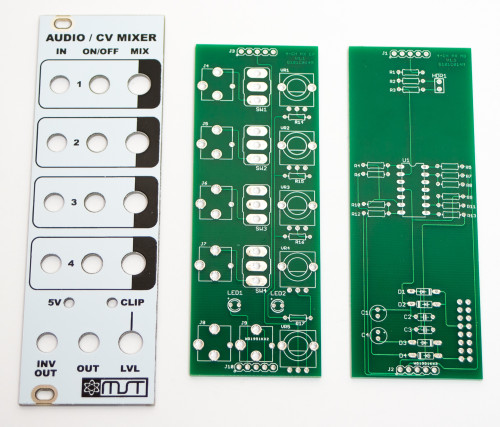
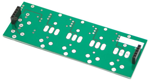
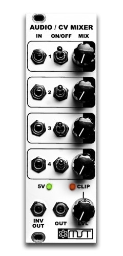
MST AUDIO CV MIXER PCBs & PANEL
Thank you for purchasing the MST Audio / CV Mutable Eurorack module kit! This is an intermediate build. If you feel like you can handle it please proceed! If not, get some help from a friend with experience or purchase a fully completed unit.
ATTN: Please follow the BOM and these instructions and don’t populate from the PCB alone. Also sometimes we cannot get the exact pictured components, so please look over your parts and check the codes first. Lets begin!
DIODES
Start with the diodes as shown below, then turn over on a firm surface to solder, then clip your leads. Diodes are polarized components so you must match the black stripe on your diodes with the white stripe on the PCB silkscreen.
MST AUDIO / CV MIXER DIODES
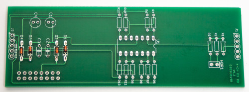
RESISTORS
Populate first, then turn over on a firm surface to solder and clip leads. Using a flat rigid card or another PCB can help hold the resistors in place as you turn the board over.
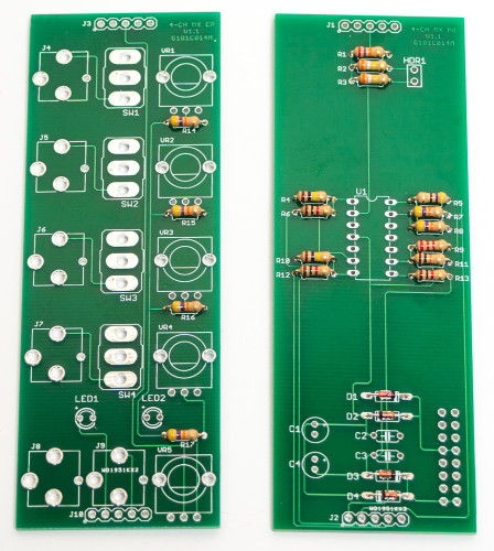
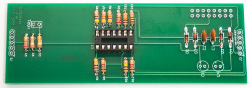
MST AUDIO / CV MIXER RESISTORS
SOCKET
Place the IC Socket by aligning the notch with the notch graphic on the PCB Silk Screen. Turn over on a flat surface and solder into place.
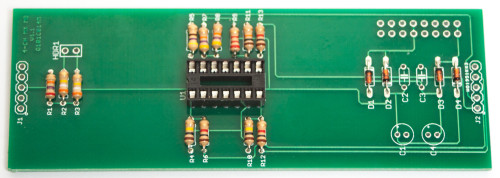
MST AUDIO / CV IC SOCKET
CAPACITORS
Add the non-polarized capacitors as shown below. Turn over to solder and clip leads.
MST AUDIO / CV MIXER CAPACITORS
Next, make sure you orient the electrolytic capacitors in correctly. The longer lead needs to be inserted into the hole that has the “+” marking near it. Turn over to solder and clip leads.
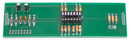
MST AUDIO / CV MIXER ELECTROLYTIC CAPACITORS
16-PIN POWER HEADER & 2-PIN JUMPER
Next add the 16-Pin Eurorack Power Connector in place by matching the key notch with the key indicator on the PCB silk screen. Turn over on a firm flat surface and carefully solder all of the pins. Now add the 2-Pin Jumper Header on the SAME SIDE of the board as the power connector as shown below.
MST AUDIO / CV MIXER JUMPER PINS & EURORACK POWER
INTEGRATED CIRCUIT & 5-PIN MALE HEADERS
Place the IC in place by aligning the notch with the notch graphic on the PCB Silk Screen and notch on the socket. Now add the two 5-PIN headers as shown below, turn over and solder.
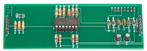
MST AUDIO / CV MIXER 5-PIN MALE HEADERS
5-PIN FEMALE HEADERS
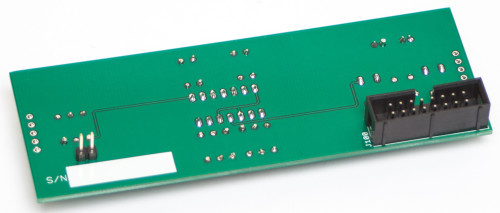
Now add the 5-Pin female headers to the rear of the control board as shown below. Turn over to solder, then trim.
MST AUDIO / CV MIXER FEMALE HEADERS
JACKS, POTENTIOMETERS, SWITCHES & LEDs
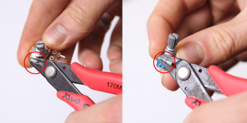
Don’t forget to cut the nubs on the potentiometers as necessary.
Now PLACE (do not solder yet!) the jacks, potentiometers, switches and LEDs in the circuit board as shown below. Make sure to remove ALL the nuts and washers from your switches before panel placement. LEDs are polarized components, make sure you place the anode (longer lead) into the pad with the ‘+’ marking next to it.
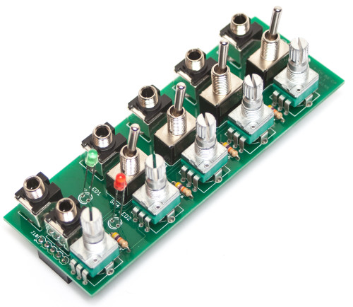
MST AUDIO / CV MIXER Pots, Jacks, Switches, & LEDs
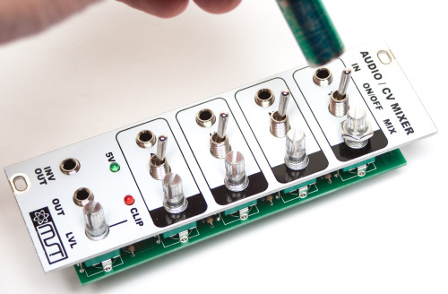
Now place the panel over the jacks, pots & switches.
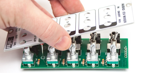
MST AUDIO / CV MIXER Panel Placement
Now fully tighten (not too hard) down the nuts on the jacks, pots and switches.
MST AUDIO / CV MIXER NUT TIGHTENING
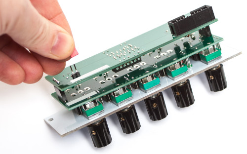
Now you will need to move the panel (please be careful and take it slow) in order to make sure that it is level with the control board. This will involve pulling the pot leads and clamps out of the board just a bit. Take your time and get this right!
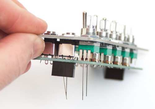
MST AUDIO / CV MIXER PANEL ALIGNMENT
Now carefully turn the board over and solder the pots, jacks and switches in place.
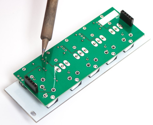
MST AUDIO / CV MIXER CONTROL BOARD SOLDERING
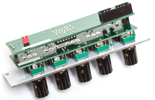
Now Carefully! connect the two boards together and NOW you are ready for testing! Plug your power cable into your Eurorack power supply and test away.
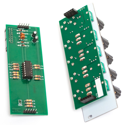
MST AUDIO / CV MIXER BOARD CONNECTION
MST – 4 CHANNEL AUDIO / CV MIXER
When you have the jumper connected to BOTH pins the mixer is setup to output a maximum output of ~5v
MST AUDIO / CV MIXER JUMPER 1
When you have the jumper disconnected on one or more pins the mixer is setup to output a maximum output of ~8V to the rail.
MST AUDIO / CV MIXER JUMPER 2
OPTIONAL BOARD TO BOARD GLUING
After you have fully tested your unit and have determined that it is in full working order, you can use some super-glue to bond the board to board headers together. This is an optional step, but will help keep the boards together as you pull the module out of your case. Make sure to not over-glue as you may still need to pull the boards apart in the future. After that, you are ready to use your module with full confidence. Thank you for choosing Synthrotek!
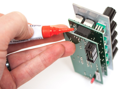
MST AUDIO / CV MIXER HEADER GLUING
Hey, I’m just going through the BOM and noticed that you have listed all the pots as being Linear. Seeing as this primarily for audio and not CV, wouldn’t it be nicer to use LOG pots?
Hey there,
The way the ciruit was designed was so that it could handle both Audio and CV equally, and with the pots that are in there, it has a nice smooth ramp no matter what you put through it.
Best,
-Patrick at Synthrotek
I just put together this kit and I found that one of the threading inside one of the black knobs was stripped, so I couldn’t tighten the screw all the way. Is it possible to get a replacement black knob? Thanks!
Hi Henry, send us an email at synthroteksales@gmail.com with your order number and address and I will send it right out!
Sorry for the delay, just saw this, hit us up at info@synthrotek.com and we will take care of it!
Just got this kit and wondering what the 4 standoff and 8 screws are for, which are in the BOM but not in the build instructions.
Thanks
Hi Earl, must have sent an extra bag in your order by accident! Sorry about that