


Important Links
Product Page
Store Page
Assembly Instructions
Bill of Materials
Schematic
Capacitor and Resistor Lookup Guide
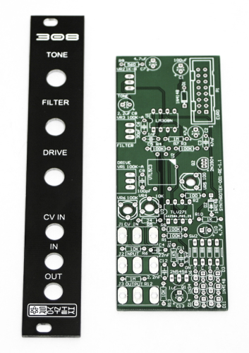
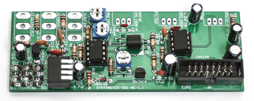
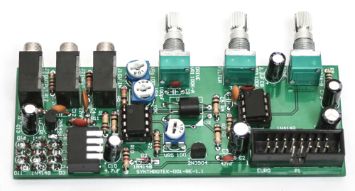
308 Distortion PCB & PANEL
Thank you for purchasing your 308 Eurorack Distortion Kit, please follow the instructions to ensure that you have a fully functioning unit. ATTN: Please follow the BOM and these instructions and don’t populate from the PCB alone. Also sometimes we cannot get the exact pictured components, so please look over your parts and check the codes first. Let’s get started!
Resistors & Diodes
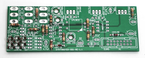
308 Distortion Resistors & Diodes
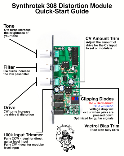
First, start by populating the resistors and the diodes, as shown above and below, then turn over on a firm surface to solder then clip your leads. Diodes are polarized components so you must align the black stripe on your diodes AWAY from the larger circle on the silk-screen. In other words, place the black-striped side towards the via (hole) that has no circular silk screen on it. Make sure that you place all of the germanium diodes on the area shown in the photo below and do the same for the 4148 silicon diodes. When using the product press down the two “red” (they will not be red or blue on the actual switch) piano switches for symmetrical germanium diode clipping. Press down just one for asymmetrical. Press down the two “blue” switches for symmetrical silicon diode clipping. Just one blue for asymmetrical clipping. When any pair of diodes is pressed down there will be a volume drop in the circuit. Feel free to arrange these in combinations that sound best to your ears! You do not need to press any of the switches down for the distortion to function, the clipping diodes are there for optional tone adjustment.
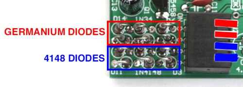
308 Distortion Diode Placement & Selection
Sockets & ICs
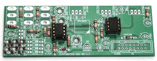
308 Distortion Sockets and ICs
Place the IC Sockets in place by aligning the notch with the notch graphic on the PCB Silk Screen. Turn over and solder. Then place the ICs in the sockets as shown above. Make sure the notch or “pin-1” circular indent is aligned to the side of the socket with the notch.
308 Distortion Trim Pots, Caps, Vactrol and 16-Pin Power Header
308 Distortion Trim Pots, Caps, Vactrol and 16-Pin Power Header
First populate the ceramic (non-polarized) capacitors, turn over, solder and trim leads. Next add the transistors by matching the flat side of the transistors with the flat side on the silk screen. Now place the electrolytic capacitors in correctly. The longer lead needs to be inserted into the hole that has the “+” marking near it, turn over solder and clip. Then place the 16-Pin Power Header by aligning the notch on the header with the notch on the PCB Silk Screen, turn over and solder. Place the trim pots in, turnover and solder. Next add the piano switch (as shown above) turn over and solder. Turn over, solder and clip leads.
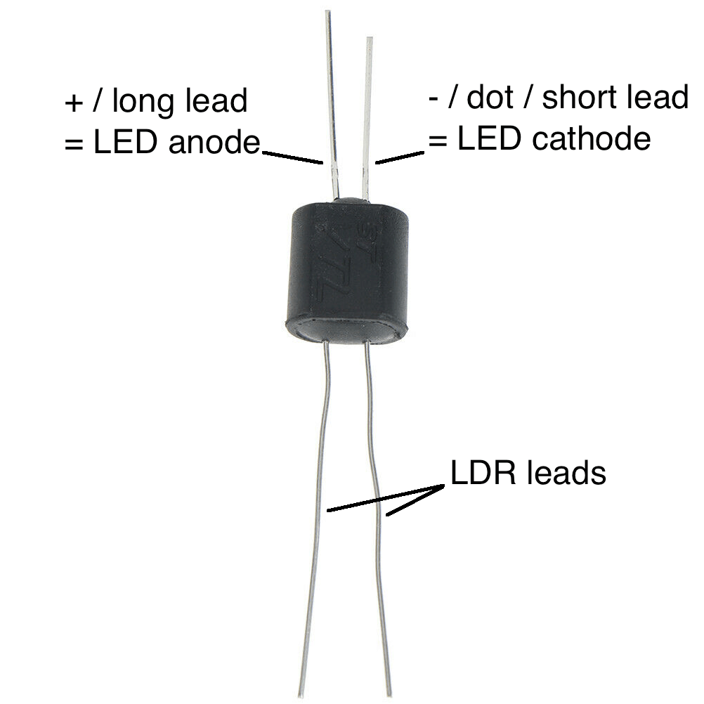
NSL-7053 Vactrol
Add the NSL-7053 vactrol by aligning the white dot on the vactrol with the white triangle on the PCB silkscreen graphic.
VTL5C3 Vactrol
There is a small “+” sign on the side of the vactrol that needs to be oriented on the OPPOSITE side of the dot on the PCB. Look for the red + in the picture below for the proper alignment.
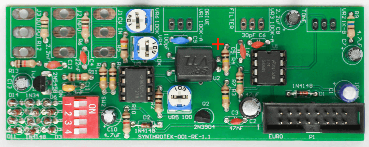
Align the + on the VTL5C3 with the red plus in the picture
Potentiometers & Jacks
First trim the alignment nub off the pots, as this will create a ‘wanky’ front panel.
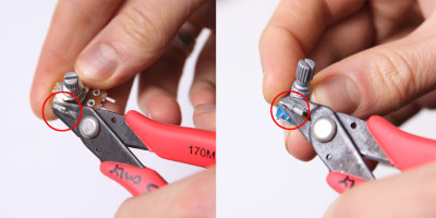
Next add the Pots and Jacks, solder then trim.
308 Distortion Jacks and Pots
Front Panel & Knobs
Add the front panel to your unit and tighten down the nuts carefully and do not over-tighten. The knobs can now be added and aligned as shown below.
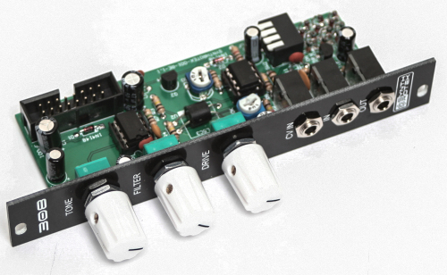
308 Distortion Complete Build
Calibrating & Testing Procedure
Plug a sine or triangle wave into the 308’s input (IN). Make sure to monitor the OUT!
Turn the TONE knob fully clockwise, turn the FILTER knob fully counter clockwise, and turn the DRIVE knob fully clockwise.
CALIBRATING INPUT LEVEL:
Turn trimpot VR6 fully clockwise. This sets the 308 up to be modular level (10VP2P).
CALIBRATING DRIVE AMOUNT – PART I:
The trimpot VR4 sets the DRIVE amount. Turn the trimpot fully counter clockwise. Now very slowly start to turn VR4 clockwise until you hear the volume duck down just a bit. If set too high (fully counter clockwise), the front panel controls will not have much of a range.
CALIBRATING CV CONTROL AMOUNT:
The trimpot VR5 sets the CV control amount. At this point it’s very handy to have a modular that provides an offset or a really long 0-5V gate. Plug in a +5V offset into the CV IN jack on the 308. Slowly turn VR5 until you hear a more intense “buzzing” sound. This sets it up to where you get a better sweep and larger range for the CV IN, and now it’s good for unipolar voltage sources (0 – 10V).
CALIBRATING DRIVE AMOUNT – PART II:
At this point you’ll want to take the output of a Sequencer (0-8V) and plug it into the CV IN jack on the 308. Set up a sequence of low to high notes and adjust VR4 to taste. You will get a thinner sound when VR4 is set fully clockwise and a fatter sound when it is set around noon or fully counter clockwise.
TESTING DIODES:
SW2 is a 4 position DIP switch that allows you to select different diodes. Flip the switches 1 and 2 into the “up” position and the volume should slightly drop but you’ll get a slightly different sounding distortion. 1 & 2 are silicon diodes.
Now flip switches 1 and 2 into the “down” position. Flip the switch 3 and 4 into the “up” position and the volume should drop a bit and you’ll get a different sounding distortion. 3 & 4 are germanium diodes.
NOTE: If you like the sound of either of these pairs of diodes, you can adjust trimpot VR6 to make up for the volume drop but it will probably make the DRIVE more sensitive to CV voltage levels which may or may not be to your liking.
-_-
CONGRATS! You are now done with your project and can test the unit in your Eurorack system. Check out the Quick Start Guide, if you like and if you have any questions or need help debugging, please first refer to our troubleshooting guide BY CLICKING HERE. If this gets you nowhere, please contact us by email for support. Thank you again for purchasing your kit from Synthrotek!
My first build… If a noob like me can do it, anybody can!! Worked the first time with no troubleshooting… Everything was clear.
Are there any “authorized” dropin replacements for the tlv271?
I screwed up the other night after a few too many brews and plugged something “bad” into the cv of my 308, I love my 308, and I need her cv. The opto went too, Ive got them, I just need to get the op-amp, and its rare down here in aus. I can source many surface mount versions here, but Im paying a fortune for them overseas, can you recommend any that may “get me by”.
Cheers
Brett
Can I also use another value (10k for example) for that 1k pot?
Thanks!
You can use a 10k pot for V2. It may be a little strange to tune in but you should be able get the same sounds with a 10k as you will with a 1k. You’ll just have a wider range to deal with (which could be good!)
-Zach
Thanks!
In the very first picture: http://www.synthrotek.com/wp-content/uploads/2014/11/308_assembly-2.jpg
the diodes are REVERSED to what is shown in picture http://www.synthrotek.com/wp-content/uploads/2014/11/DIODE_SELECTION.jpg (the close up picture)
What is the right way? If I read correctly: “In other words, place the black-striped side towards the via (hole) that has no circular silk screen on it” It must be that the second picture (the close up picture) is the right one.
Then this means that on every other picture than the close up, it is pictured WRONG ??? It that true?
Sorry…I just noticed that “technically” if you follow either picture it wont matter.
Its just a switchable daisy chain to ground, so following either phot works.
…hey I said I was pissed.
Cheers
vR6 is not on the schematic. Where is it?
Hey John, it looks like our schematic on our site may be out of date. VR6 is a 100K trim pot that should be placed between R6 and J2. Hope this helps!