Important Links
Product PageStore Page
Assembly Instructions
Bill of Materials
Manual
Capacitor & Resistor Lookup Guide
Thank you for purchasing the Synthrotek USB Power kit! This is an easy to intermediate build. It is very important to get all the components properly soldered into the PCB in the correct order and placement. If you feel like you can handle it, please proceed! If not, get some help from a friend with experience or purchase a fully completed unit.
Resistors
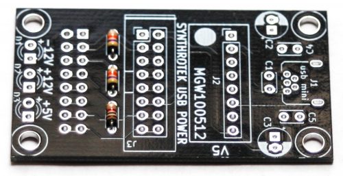
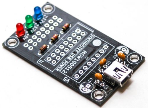
Populate the resistors on the logic board. Resistors are non polarized, so it doesn’t matter which direction you put them on the PCB, but it will help with any troubleshooting that may arise if you line up all the tolerance bands (usually a gold stripe) on one side. This will make it easier to read the color codes on the resistors.
Once they are in place, carefully flip your project over and solder the components in place. Clip any excess leads on the bottom of the board.
LEDs
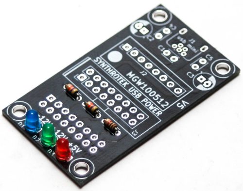
Now place the three 3mm LEDs into the PCB by aligning the longer of the two leads into the hole that is by “+” side on the board. Carefully flip your project over and solder the LEDs in place. Clip any excess leads.
USB Jack
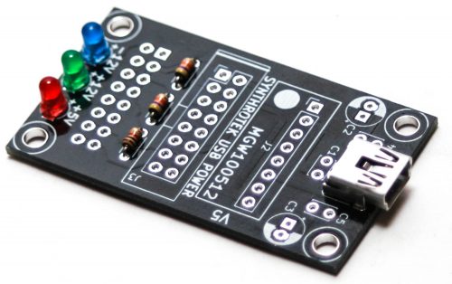
Place the USB MINI jack into the PCB, carefully turn the board over to solder the pins. These pins are quite close together so please take your time while doing this.
Ceramic Capacitors
Populate the three ceramic capacitors as show below. These are not polarized components. After placing the caps, carefully turn over and clip the excess leads.
Electrolytic Capacitors
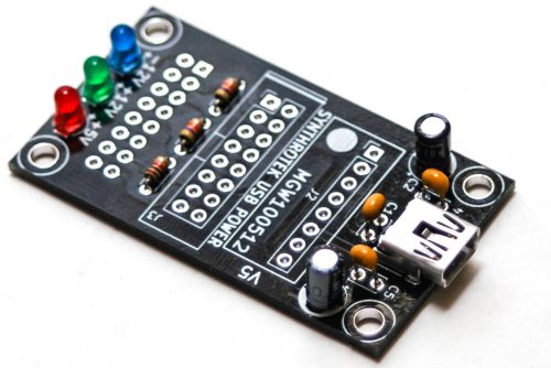
Up next are the electrolytic capacitors. The electrolytic capacitors are polarized, so make sure when populating them that the longer lead goes into the hole with a “+” next to it. Once you have everything in place, flip the project over and solder everything into place. Clip the excess leads.
16-Pin Power Connectors: Two options
Option 1: For plugging into Bus Cheeks or bus board
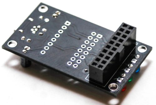
Adding the bottom 16 pin socket on the bottom of the board is optional. This is a good option If you are planning on plugging this power supply directly into a bus board (option 1). You will want to omit this step if you are screwing down your USB Power to a case via standoffs and screws (option 2). It is also ok to leave this second connector unpopulated.
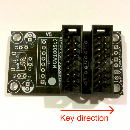
When using a keyed female connector (as shown below) make sure that you place the connector with the key facing the short end of the board (as shown below). Carefully turn your board over to solder the pins in place.
Top Power Connector
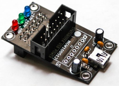
Next, place the keyed 16-pin shrouded connector into the PCB with the notch in the connector aligned with the notch on the silk screen. Carefully turn over and solder in place.
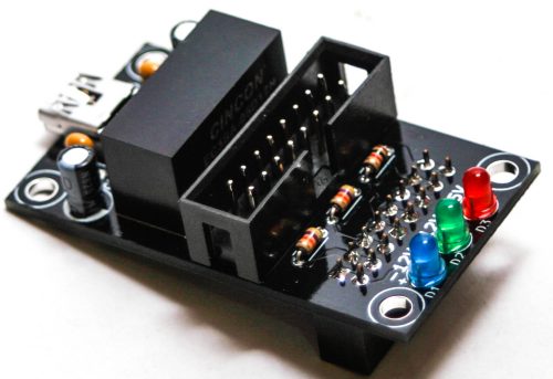
Option 2: Two headers on top
Two 16-pin headers can be placed on the top side of the PCB so that the circuit can easily be screwed down or mounted into a case. Note in the picture above that the key for both connectors faces the same direction as the silkscreen for J3.
Voltage Regulator
Finally place the voltage regulator into the PCB as shown below, carefully turn over and solder in place and clip excess leads.
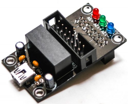
Final Project
Congrats! You can now plug in your project and start powering a small number of modules!