


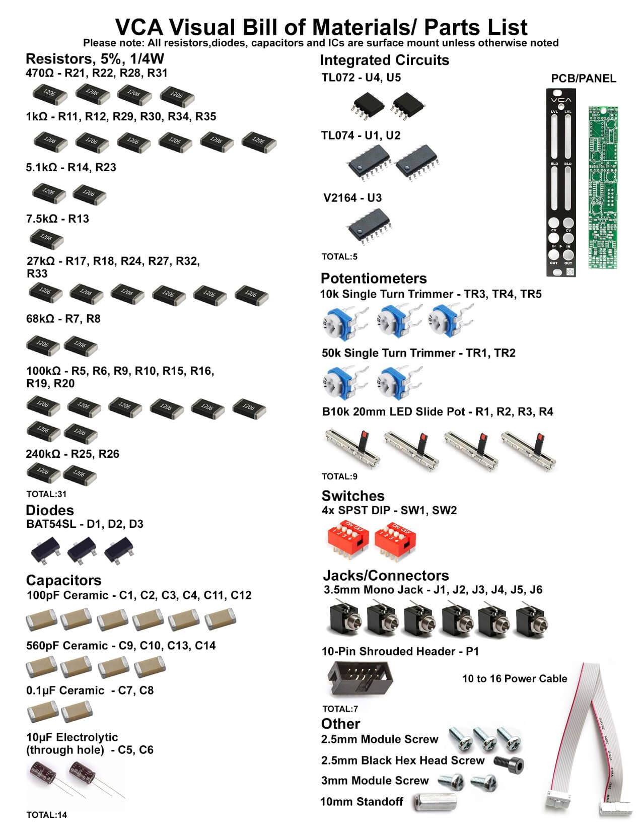
Thank you for purchasing the Synthrotek VCA. This is an intermediate to advanced build as it is requires surface mount (SMD) assembly. These parts are VERY small and easy to lose, or install incorrectly without experience. It is very important to get all the components properly soldered into the PCB in the correct placement. If you feel like you can handle it, please proceed! If not, get some help from a friend with experience or purchase a fully completed unit.
Please build according to the BOM, and not these instructions or the pictures alone. Some components may have changed since these were written, or we may not be able to get the exact looking components in the pictures.
 Here’s a link to a BOM with Mouser part numbers.
General Advice on SMD Soldering
SMD soldering is a different beast compared to through hole soldering. We encourage you to take extra time and to be careful as you open the bags containing these very small components.
We suggest adding a small amount of solder to one of the pads that you will be working with PRIOR to placing the component. Using a good pair of tweezers, place the component on the pads and carefully reheat the solder on the pad that was tinned. If the placement looks good, then go ahead and solder the component to the pads.
Recommended tools:
- small tweezers
- magnifying glass
- fine soldering tip
Resistors, Ceramic Capacitors, Diodes and IC
We will start off my placing the three diodes on the PCB as shown below. Add some solder to one of the pads prior to placing the component; a small amount is enough. You can then use tweezers to hold the diode in place while tacking it down.
Resistors and ceramic capacitors are not polarized and can be placed either direction. Solder these using the same method as the diodes.
For the ICs, there is either a line or a dot that marks the ‘top’ the IC. Align the line or dot toward the notch on the PCB silkscreen. Add a very small amount of solder to one pad, then carefully place the component and tack down one leg with your soldering iron. Make sure the IC legs are still covering the rest of the pads before proceeding. Then solder one of the legs on the opposite side, then solder the rest of the legs.
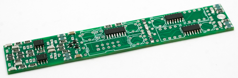
VCA SMD IC’s, CAPS, RESISTORS and DIODES
Electrolytic Capacitors
Electrolytic caps are polarized, so place the long lead into the hole that has the “+” next to it. Carefully turn over to solder and trim the leads.
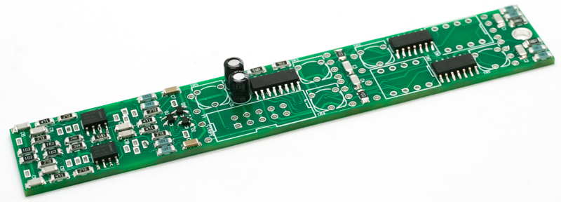
VCA SMD ELECTROLYTIC CAPS
Exponential / Linear Switches
Place the two dip switches into the PCB as shown below. Carefully turn PCB over and solder in place.
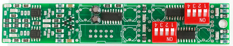
VCA SMD Curve Switches
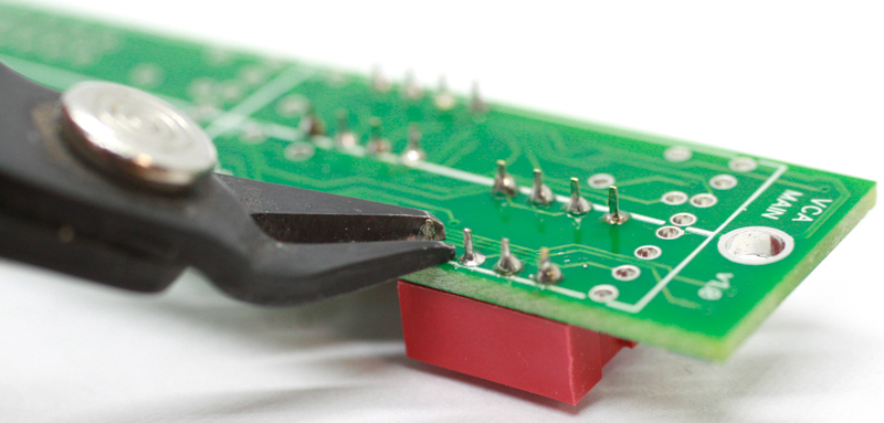
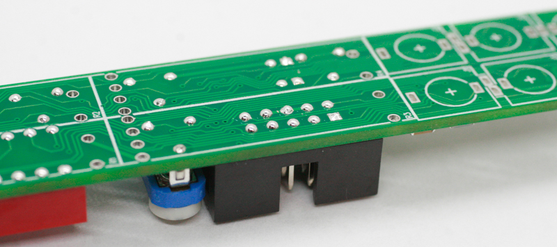
Next, trim the excess leads very close without scratching the PCB. The leads should not be flush with the PCB, just sticking up a tiny bit. They need to be short enough that the slide pots can sit squarely on the board, so if you aren’t sure if the leads are low enough, put a slide pot on top without soldering, and see if it sits ok.
VCA SMD TRIM
After leads are clipped, add a small amount of solder. Keep the rise of the solder very low.
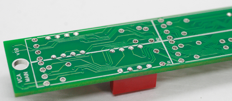
VCA SMD Lead depth
Trimmer Potentiometers
Place the five trimmer pots into the PCB, carefully turn over and VERY closely trim the excess leads.
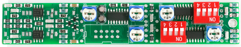
VCA SMD Trimmer Pots
Add a little solder if needed, but keep the solder rise very low.
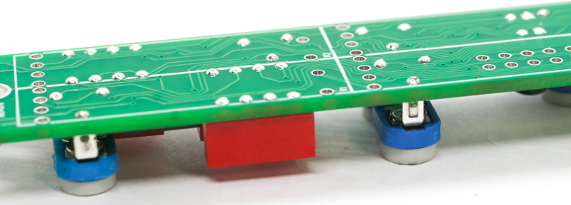
VCA SMD Trimmers
Power Header
Place the 10-pin power connector into the PCB by aligning the notch on the connector with the notch on the PCB silk screen. Carefully turn the project over and solder the pins in place.
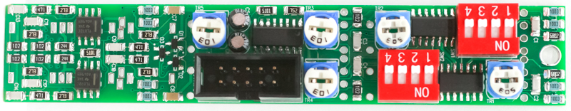
VCA SMD Power Header
Trim the pins very close to the PCB without scratching the PCB! Add a little solder if you need to, BUT KEEP IT LOW!!
VCA SMD Power trimming
Jacks & Standoff
Take the standoff and the standoff screw and secure it to the front side of the PCB as shown below. Next carefully place all the 3.5mm jacks into the PCB as shown below.
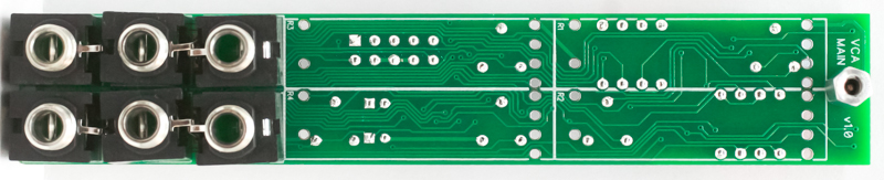
VCA SMD Jacks and Standoff
Use the panel to align the jacks prior to soldering and trimming.
VCA JACK ALIGNMENT
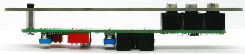
Slide Potentiometers
Add the slide pots as shown below. Make sure that the pins on the shrouded header are not bumping into the slide pot; if they do, trim them down a little. Wait to solder until front panel placement. Turn over to solder and trim excess leads.
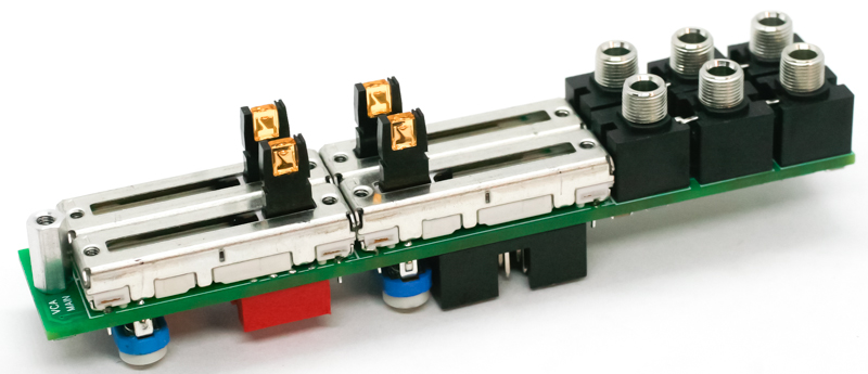
VCA SMD Slide Pots
Panel Placement
Take the panel and place it on the project and secure down the standoff screw and jack nuts. Solder in the pots, and you are ready to calibrate!
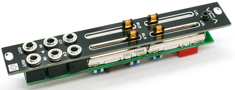
VCA SMD PANEL PLACEMENT
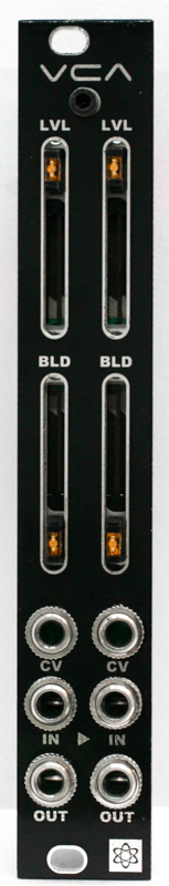
VCA SMD Panel
Calibration instructions
Notes:
- Tools needed: an oscillator, buffered mult and oscilloscope
- The SW2 DIP switch controls channel 1
- The SW1 DIP switch controls channel 2
- Switch settings:
- Exponential mode: 1 and 2 are ON (pushed upward) and 3 and 4 are OFF (pushed downward)
- Linear mode: 1 and 2 are OFF and 3 and 4 are ON
- In any other switch setting, the module will nor work properly
- Trimmer functions:
- TR1 – Exp CH1
- TR2 – Exp CH2
- TR3 – Linear CH2
- TR4 – Linear CH1
- TR5 – 5V
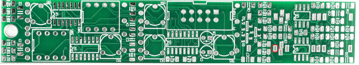
5V calibration:
First, unpatch any cables from the front of the module. Calibrate TR5 so that the voltage on the wiper pin (measurable at the circled point on the image below) measures 5V.
Linear mode calibration:
- Set the DIP switches to linear.
- Turn both Level pots all the way up and both Bleed pots all the way down. Unplug the CV jacks.
- Patch an oscillator into a buffered mult, then patch from the mult into the IN on CH1. Plug an oscilloscope into the mult.
- Patch the OUT of CH1 to the oscilloscope.
- Use the oscilloscope to compare the input waveform and the output waveform. Adjust TR4 till both waveforms match each other and are superimposed on top of each other.
- Move the oscilloscope from CH1 OUT to CH2. Adjust TR3 till both waveforms match each other.
Exponential mode calibration:
- Set the DIP switches to exponential.
- Keep the rest of the settings the same as the linear mode.
- Adjust TR1 till both waveforms match each other.
- Move the oscilloscope from CH1 OUT to CH2. Adjust TR2 till both waveforms match each other.