


Attention: These are the assembly instructions for the OLD version of the Tube Screamer PCB Mount.
If you purchased the “No Pop” version of the TS, check out the assembly instructions HERE.
Looking for Parts?
- 9mm Vertical Potentiometer – 20K Linear
- 9mm Vertical Potentiometer – 100K Linear
- 9mm Vertical Potentiometer – 500K Audio
- 1590B Pre-drilled case for Guitar Pedals
Welcome to the Toob Screamer Assembly Instructions. Except for the battery clip this kit does not use any wiring and everything is attached directly to the PCB, making it easy to make a very nice looking build. Lets get started!
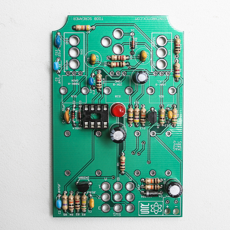
BOM Layout
If you’ve received your kit and are ready to build, the first step is to ensure you have all of the parts and familiarize yourself with the PCB and where the parts will be going.
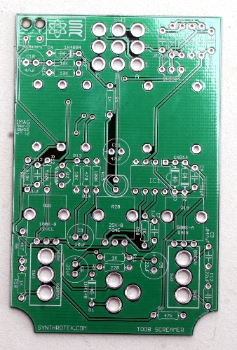
Check your kit against the Toob Screamer BOM. If you are missing anything let us know and we will ship you the part.
Assembly
Attention: Changes may occur after the Assembly Instructions are created and the photos may not reflect those changes. Always use the BOM to verify the placement of components.
Resistors
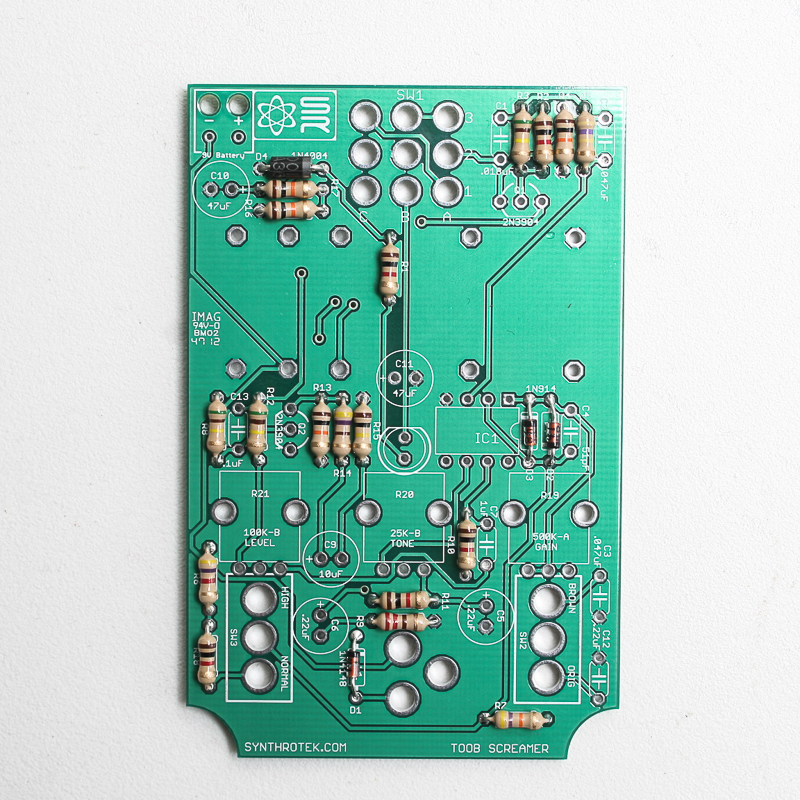
There are 18 resistors and 4 diodes to install. The resistors are not very sensitive components and are not polar components, but the diodes are polar components and must be soldered in the correct direction. On the silkscreen of the PCB for each diode there is a line on one end. You will want to match the line on the diode with the line on the silkscreen of the diode.
Capacitors
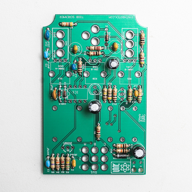
Here you will want to pay especially close attention to two of the ceramic capacitors because two of them are polar components while the rest are not. All of the electrolytic capacitors (C9, C10, and C11) are polar components. The longer lead on the electrolytic capacitors go into the hole that is marked with a ‘+’ sign. And then the two tantalum capacitors (C5, C6) that look like the other ceramic capacitors are also polar components and, like the electrolytic capacitors, you need to ensure that the longer lead gets inserted into the hole marked with the ‘+’. All of the other capacitors are not polar components and you can insert them in any direction.
LED, Transistors, and IC Socket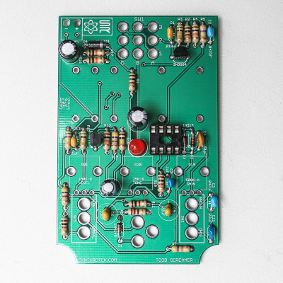
Next we will install the LED and Transistors. Both of these components have one side that is flat which match up to the silkscreen on the PCB board. If you have a hard time identifying the flat side on the LED, the side which has the shorter lead has the flat side. And then the IC socket will have a notch on it that you will want to make sure aligns with the notch on the PCB’s silkscreen.
Power Adapters, Switches, and Pots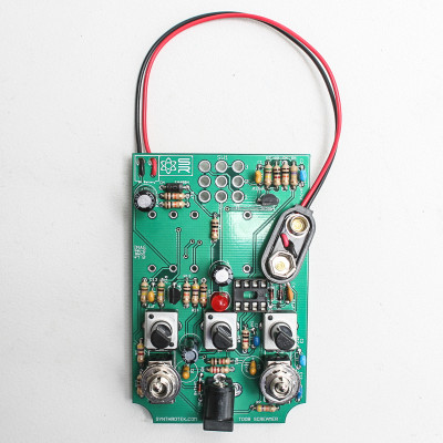

Next you will want to install the Pots (R19, R20, R21). When soldering the pots into place you will want to also solder in the side-clips to ensure that the pots are secured to the PCB and will not easily come loose. For the battery clip, ensure that you attach the red wire to the ‘+’ point and the black wire to the ‘-‘ point. And then solder the switches and the DC power jack into place.
When installing the pot, some pots come with nubs near the shaft that may get in the way of installing the circuit into a case. Check for a nub and clip as necessary.

Don’t forget to cut the nubs on the potentiometers as neccesary.
Stomp Switch and Audio Jacks
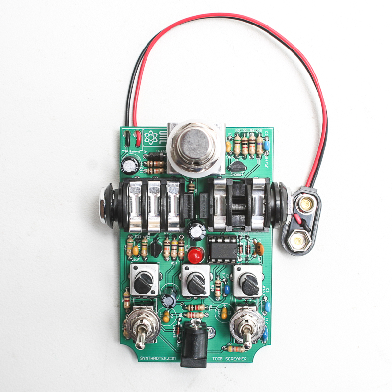
We’re almost done! The audio jacks will be easy to install, just make sure you install the mono jack into side that only has the two holes and not into the mounts for the stereo jack, which will have a total of six holes. And then when you install the stop switch, make sure that the sides of the switch that are all the blue plastic are facing the top/bottom of the PCB while the sides of the stomp switch which have the metal draped over are facing the sides of the PCB. If you can’t get the stomp switch to go in, don’t force it, try it in a different direction.
Project Completed
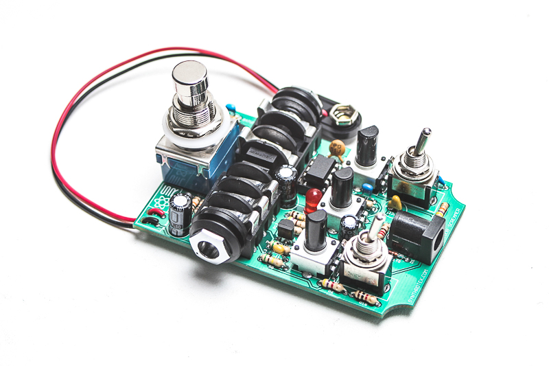
Congrats! Your Toob Screamer is complete. Hook it up and have some fun!
[…] Toob Screamer Assembly Instructions […]
Hey I bought the Board alone and Im trying to find the pots for this online are they alps pots? if so where do you get them? Can I buy them from you? Thanks Kevin Scott
Hi Kevin, we have them here, they are 1.50 each. You can also get almost any 9mm vertical snap in pot. Bourns, Alps, alpha, all have them too. Thanks for the purchase!
I would like to buy the three pots and a 2.1 mm 9 volt adapter can you send me a bill and do you take pay pal?
Hey there,
I am close to completing the project but was planning on putting into a Hammond 1590B case that the pcb was designed for but there is one problem: the switches and pots are not long/tall enough to fit into the case with the 1/4 jacks and the stomp box switch.
This could be something that we should figure out together considering I believe people would like to do the same thing I am doing without much hassle.
An alternative solution I was thinking was soldering a bit of wire on the pots and switches but that defeats the purpose of the fancy pot and switch design on the pcb. Maybe another solution would be taller pots.
I also would like to help draw up a drill template but would like to fix this problem first.
Hi Christian,
Sorry to hear you’re having issues. Problems like yours are actually why we recently updated the design for off-board components. We were using some tall knobs for the pots that would reach far enough down. I can’t say we encountered major issues with the switches but some wiring will work.
Hey guys, can’t wait to start this build! Any tips for assembling this for a perfect fit in the pre-drilled enclosure? I could use hook-up wire I suppose but thats not what this kit is about. Just wondering 🙂 Thanks!
Hi Stu, the hard components (pots, switches, jacks) do fit nicely even after soldered on. BUT you can also solder one lug of these hard components, attach the enclose and then solder the rest of the lugs from inside the case onto the PCB, this is double safe.
@Steve Harmon
Thanks! That is a great idea!
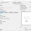
Hi, I can’t get the drill template my Hammond 1590B case to print at 100%. My print preview says the image is scaled to 21%. I changed the scaled setting to 100%, but my printer still prints the template too small. Please help me.
When you print, you want to select the ‘Actual size’ option under Page Sizing & Handling. See this image for the settings that we use to print our drill templates:
Got this one done, finally, and have some questions.
1. The Gain (Left) pot and the Tone(middle) pot have almost no effective travel. The gain is fully down (still gritty) full right, about 2:00 it changes to a bit more distortion, then it stays the same all the way to full left. Tone stays pretty bassy till about 10:00, then gets a drastic treble boost till full left. Is this normal?
2. The right switch (beef mod) creates a drastic volume drop when engaged (switch toward ac jack). The left switch seems to work OK, it provides a high end boost when engaged. Is this correct?
Hello Wayne. This version of the PCB Mount Tube Screamer is discontinued and sadly we don’t have one built up here at the shop for diagnosing / testing, and the guy who designed it is no longer working for us. Maybe give our Troubleshooting guide a look over and see if there’s anything that can help you out? http://www.synthrotek.com/tech/troubleshooting-your-build/
How much for the kit and shipping for BRAZIL, RIO DE JANEIRO
Hi Jairo, it would be $82.31 total.