


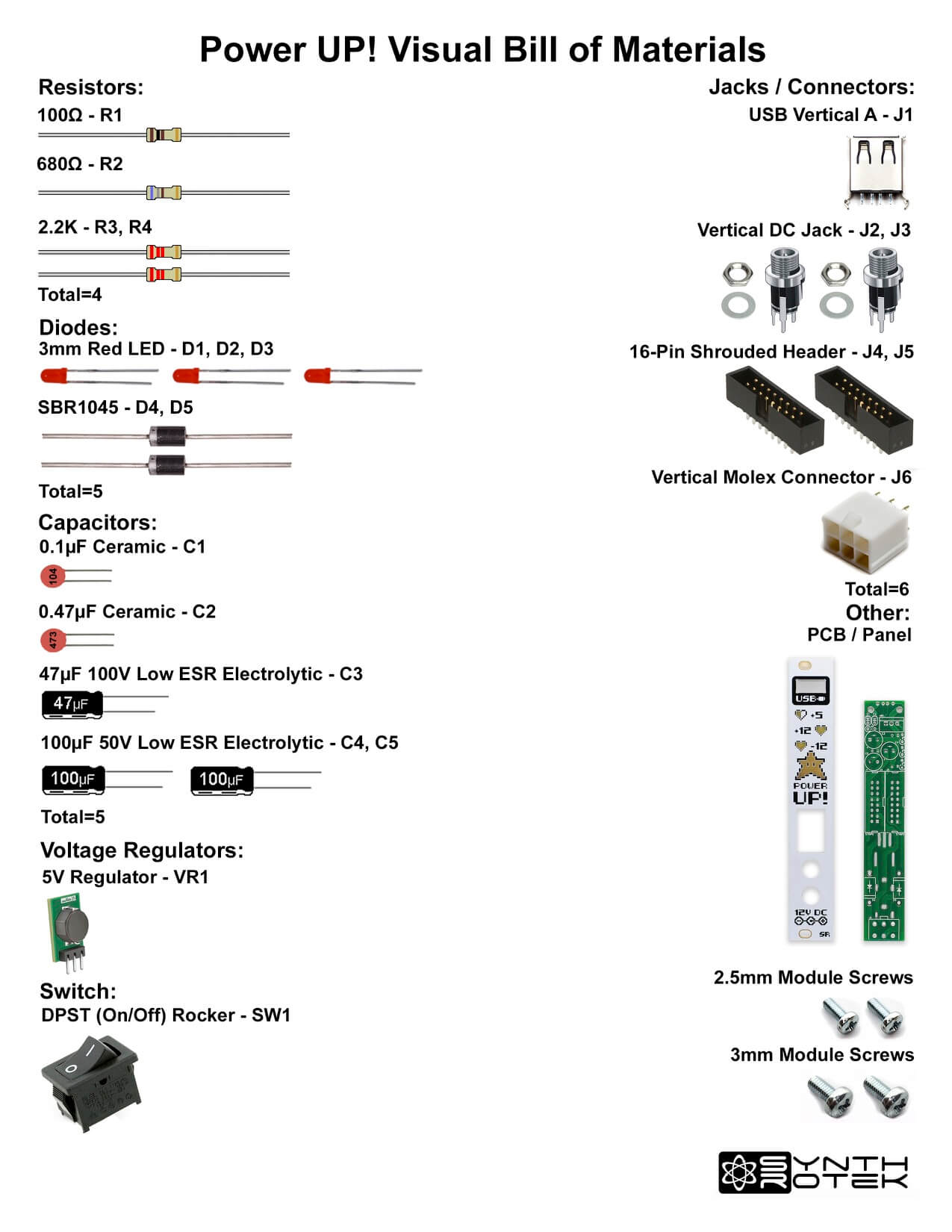
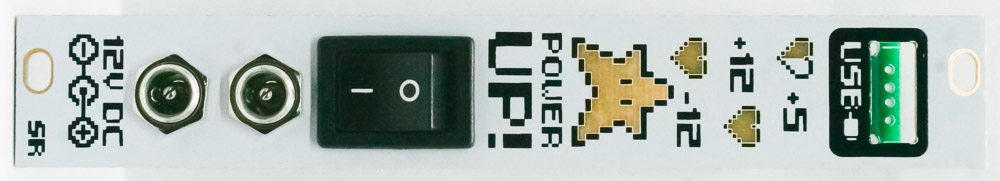
Power Up! Assembly
Thank you for purchasing the Synthrotek Power UP! – Eurorack Power Supply Kit. This is an intermediate build. If you feel like you can handle it, please proceed! If not, get some help from a friend with experience or purchase a fully completed unit.
Please build according to the BOM, and not these instructions or the pictures alone. Some components may have changed since these were written, or we may not be able to get the exact components in the pictures.
 Click here for a list of parts with Mouser part numbers.
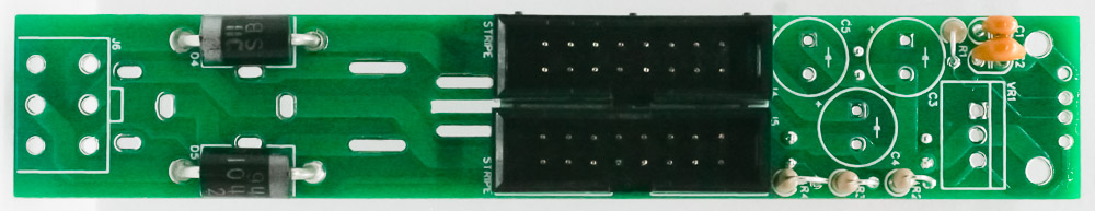
DIODES
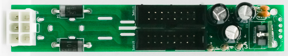
Place the two large diodes into the PCB shown below by aligning the silver polarity band on the diode with the white band on the PCB silk screen. Turn the project over to solder and then clip excess leads.
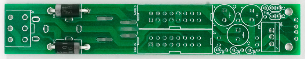
Power UP! Diodes
RESISTORS
Place the resistors into the PCB shown below by bending the resistors over first. Resistors are not polarized, so you can place them either way. Turn the project over to solder and then clip excess leads.
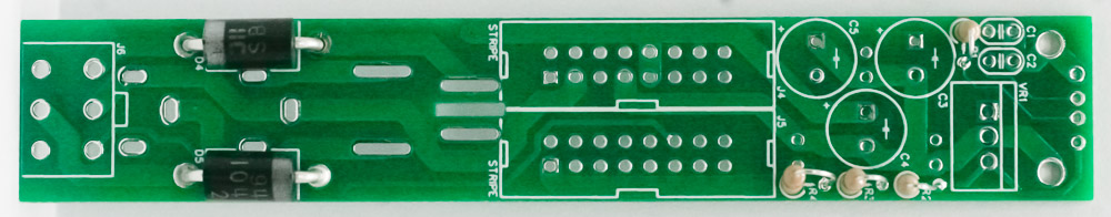
Power UP! Stand Up Resistors
CERAMIC CAPACITORS
Place the two ceramic cap into the PCB as shown below. These caps are not polarized, so place them in either way. Turn the project over to solder and then clip excess leads.
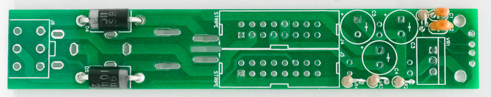
Power UP! Ceramic Capacitors
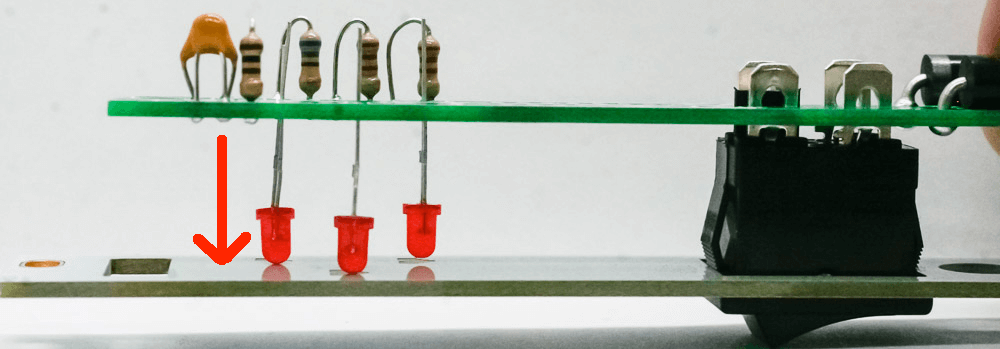
LEDs and Power Switch
Place the three LEDs into the PCB as shown below (don’t solder yet). These LEDs are polarized, so place them in by aligning the longer lead of the LED with the “+” on the PCB silk screen.
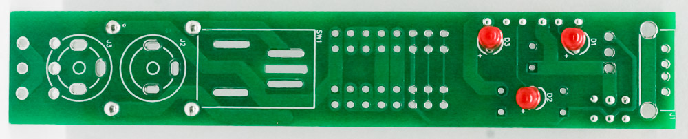
Power UP! LEDs
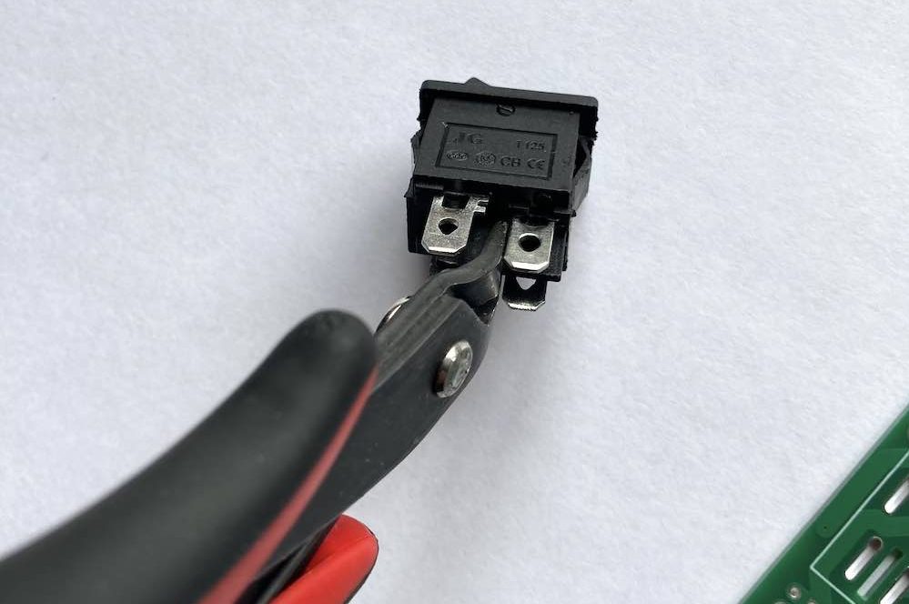
Some DPST switches have a long tab at the center of the switch. If your switch is like this, it’s easy to fix. Using a pair of snips, clip the tab as shown here:
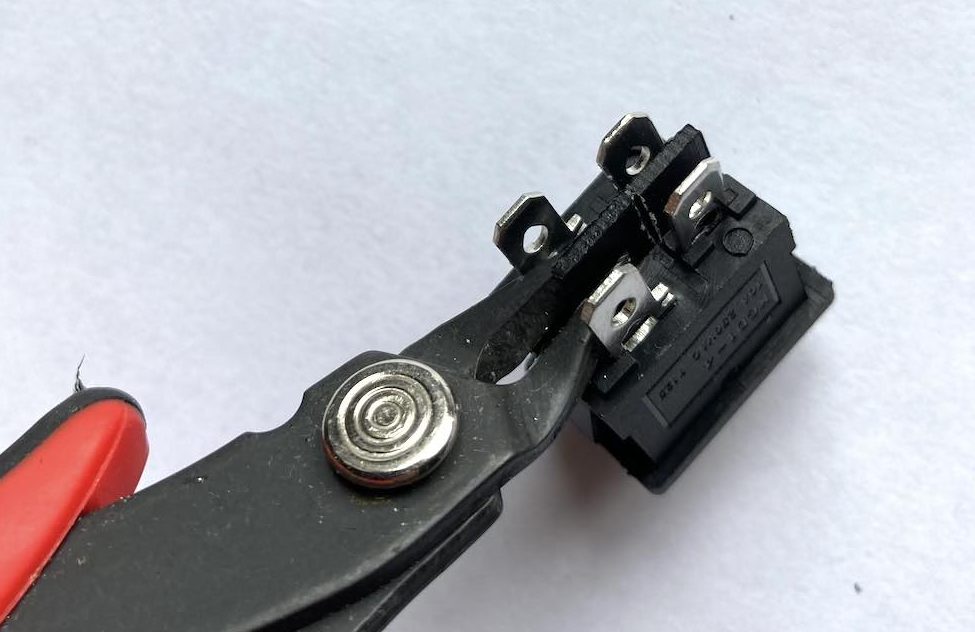
Clip it again as shown here. Keep clipping until the tab comes out.
When the tab is clipped correctly, the switch will fit into the board nicely:
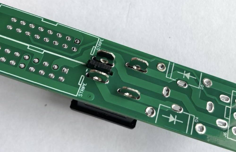
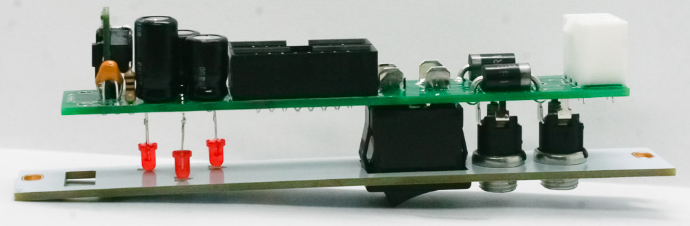
Push the power switch into the panel as shown below and make sure that the switch leads line up with the holes on the PCB. Do not solder the switch into the PCB just yet. Push the LEDs down until they come in contact with the panel. You can now solder in the LEDs and clip the excess leads.
16 PIN EURORACK POWER CONNECTORS
Place the two 16 pin power connectors into the PCB as shown below by aligning the notch on the connector with the notch on the PCB silkscreen. Carefully turn over and solder in place.
Power UP! Eurorack 16 Pin Connectors
ELECTROLYTIC CAPACITORS
Place the three electrolytic caps into their respective places. Align them by placing the longer leads near the hole that has the “+” near it. Carefully turnover to solder in place then trim excess leads.
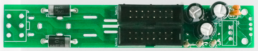
Power UP! Electrolytic Capacitors
MOLEX CONNECTOR
Place the Molex connector into the PCB as show below by aligning the notch on top of the connector with the notch on the PCB silk screen. Turn over to solder in place.
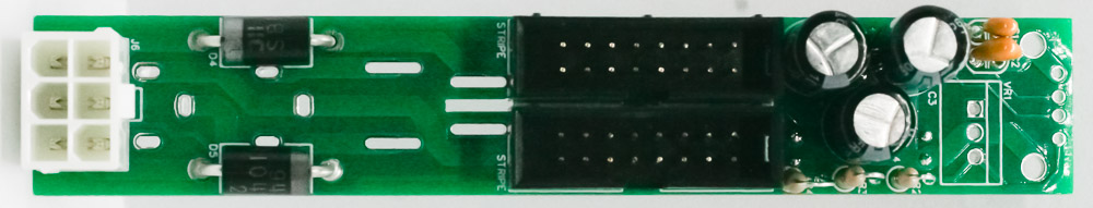
Power UP! Molex Connector
5V CONVERTER
Place the 5V Converter into the PCB as show below by aligning the flat PCB part of the converter with the silk screen. Turn over to solder in place.
Power UP! 5V Converter
DC JACKS
Place the two DC Jacks into the PCB through the panel (time to solder that power switch!).
DC POWER JACKS
Finger tighten the DC Jack nuts then turn the project over to solder the DC jacks and power switch.
Power UP! Jack NUTS
USB Jack
Place the USB Jack through the panel and into the project as shown below and solder the pins in place.
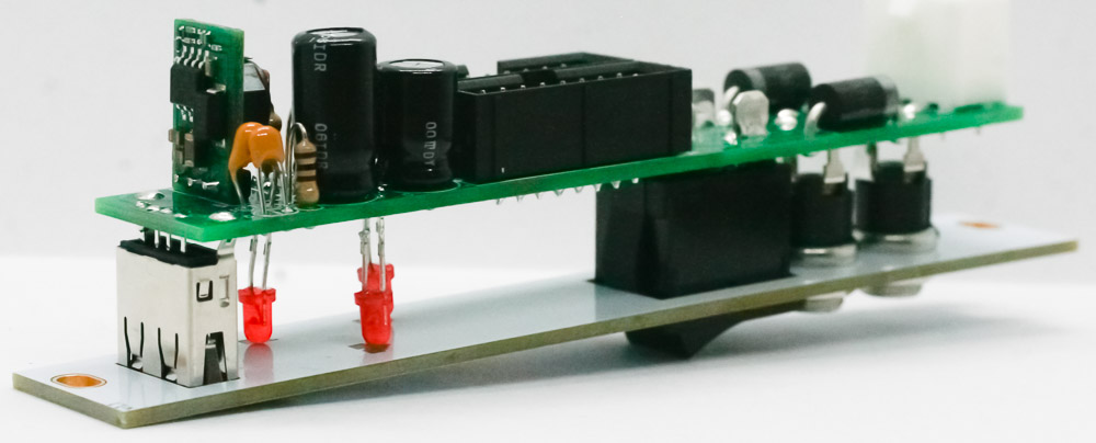
Power UP! USB Jack
Power UP! USB Jack 2
HERE’s to YOU! You can now tighten those DC nuts a bit more and then test you unit! Thank you for choosing a Synthrotek product.
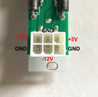
Here is the molex connector pinout in case you need it.