


Important Links
Product Page
Store Page
Assembly Instructions
Bill of Materials
Schematics
Capacitor and Resistor Lookup Guide
Welcome to the NEW Atari Punk Console w. CV Input Assembly Instructions! If you’re new to circuit-building, this is a great kit because it’s easy and makes some crazy sounds. Let’s get started!
BOM Layout

If you received your kit and you’re ready to build, the first step is to check to see if you have all of the parts. Check your kit against the APC BOM. If you’re missing anything, we’ll send it to you free of charge.
Assembly
Attention: Changes may occur after the Assembly Instructions are created and the photos may not reflect those changes. Always use the BOM to verify the placement of components.
PCB Components

Line up the half-moon notch on the IC socket with the notch drawn on the PC board.
Capacitors

The next part of our build are the capacitors. C1, C2, and C4 are non-polar ceramic capacitors, so their leads can go in either through-hole their silkscreen designates. They look similar, but they have different values that are printed on their body in small lettering. C1 will have a ‘103’ and C2/C4 will be labeled ‘104’.
C3 and C5 are 10μF polarized electrolytic capacitors. These capacitors must be placed correctly for the circuit to function correctly. Most electrolytic capacitors have a thin band on their body (grey in the picture above) that denotes the negative lead. New electrolytic capacitors will also have a longer positive lead.
On the PCB, C3’s silkscreen identifier has a square through-hole with a ‘+’ next to it. This is where the positive lead is inserted. The negative lead is inserted into the circle through-hole.
Resistors/Diode

There are 4 resistors to place onto the PCB. R1 and R2 are 1kΩ resistors (colored brown-black-red-gold), R3 is a 4.7kΩ resistor (colored yellow-violet-red-gold), and R4 is a 10kΩ resistor (colored brown-black-orange-gold).
The Schottky diode will be used for D2. Match up the black (negative) band on the diode with the white band on the PCB.
Wired Components
Potentiometers

Our first wired components to add to the PCB are Pot1, POT2 and POT3. Pot1=A1ook Pot2, Pot3=B500k

Match the PCB through-holes to the potentiometer solder lug numbering above. Solder wires to the potentiometers, then insert them into their corresponding position.
When installing the pot, some pots come with nubs near the shaft that may get in the way of installing the circuit into a case. Check for a nub and clip as necessary.

Don’t forget to cut the nubs on the potentiometers as neccesary.
Power Connections/Jacks

Connecting the 9V battery adapter jack is easy, so we’ll do this first. The red wire is connected to the square through-hole next to the ‘+’ silkscreen. The black wire is connected to the circle through-hole next to the ‘-‘.
DC Jack Pinout
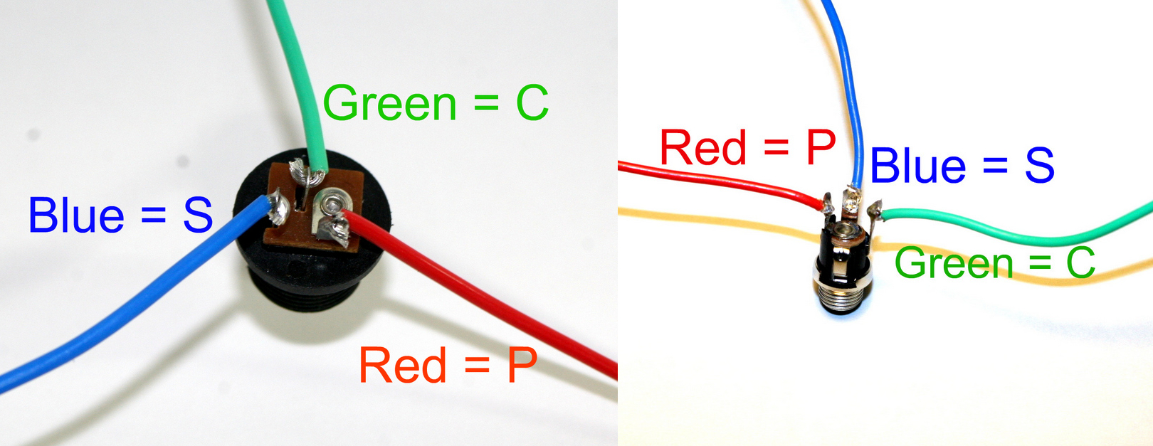
The DC Jack is fairly straightforward: P = Pin, S = Sleeve, C = Switch. Connect three wires to the DC Jack’s solder terminals and, using the picture above as a reference, connect them to the PCB at their respective through-holes. The center pin will be negative.
If you do not want to install the 9V DC jack and only install the 9V battery clip you will have to short the S and C pins for the 9V DC Jack like shown in the picture below*.
* Your PCB may not look exactly like the photo, that is ok. What is important is that you short the same pins as shown in the photo.
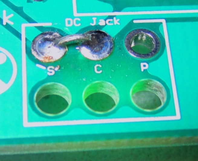
Short these contacts to get the circuit to work without the 9V DC Jack
Mono Jacks

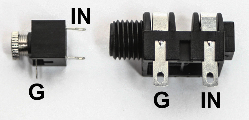
Tip (IN) and sleeve (Ground) on a 3.5mm and 1/4 inch jack
The APC needs three mono jacks for the ‘CV-IN’ and ‘OUT’. There are two solder lugs on 1/4″ mono jacks, with the ‘S’ standing for Sleeve/Ground and ‘T’ standing for Tip. On the PCB, locate the through-holes for ‘CV-IN’ and ‘OUT’ Both of these have a ‘T’ (IN) and an ‘S’ (G) next to the through-holes. Using the picture above, connect the mono jacks to the PCB.
SPST On/Off Switch

Wire the power switch as shown in the picture.
Wired LED

LEDs are polar components just like electrolytic capacitors. They also have a longer positive lead. D1 indicates whether or not the circuit is receiving power and will be the first indication that your circuit is built correctly, so this step is important.
To solder this straight to the board, insert the longer positive lead into the circle through-hole and the shorter negative lead into the square through-hole.
To wire the LED for a case, make hooks at the end of the LED leads; solder the wires to the leads. Make sure the wire connecting to the longer lead goes into the circle through-hole (which is positive) and the shorter lead into the square (negative) through-hole.
Lastly, add in the IC, aligning the notch on the chip with the notch on the socket.
Congratulations, that’s the end of the assembly! Put a battery into the 9v battery adapter jack, connect an external amplifier, turn the circuit on, and turn up Pot1. Your LED should light up, and you should have a gnarly sound coming out of your amp. If it doesn’t work, go back through the instructions and carefully check all of your work.
Have fun with your new hand-made APC!!
how to put the chip onto the notch?
Hi Moe, match the divit on top of the IC with the markings on the PCB
is C4 supposed to have a 103 marking on it?
nvm, I just needed a new battery lol
How could i modify this and add a tiny 8 ohm Speaker in addition to the output jack already provided??
Yes, I think there should be enough power.
Hi Matthías,
C4 is suppose to have the markings of 104. The markings of 103 is 0.01uF and goes with C1.
When you refer to C5 you actually mean C4 the first time, right?
Yes, the first mention of C5 actually should be C4. Thanks for making us aware of the error. It should be fixed now.
What can I say, I’m a detail oriented guy.
hi there,
if I want to run this off a 12v supply instead (a eurorack modular case) do I need to change any of the resistance / cap values?
cheers : )
Hi Buster, should be fine, this is not a 1V/octave oscillator, so if there is a pitch difference it should not affect much. Perhaps someone else can look at the schematic and let me know. I think the max voltage is 18V and the rest of the components will be fine with 12V.
Hello!
My apc is not working if I dont have something connected to the cv1 input. I am using this kind of jacks http://ecx.images-amazon.com/images/I/418NmreZC5L._SL500_AA300_.jpg
Hope you can help me out. Thanks!
Hello Miska. Looks like you’re using TRS jacks instead of TS jacks. You need to use TS (mono) jacks and not TRS (stereo) jacks for this build. On the CV1 jack with nothing plugged in, the tip is being shorted as the TRS jack is normally closed. Switching to a TS jack will be best. Still, send us some up-close & high-resolution pictures of your build. Be sure to include pictures of the top and bottom of the PCB and shots of the pots & jacks. Send them to synthroteksales at gmail dot com.
I’m curious, I got a kit with 1/8″ jacks, and I’m not sure which solder lug is “sleeve” and which is “tip.” Please advise!
Hi Robert, check out these instructions, it will show you here:
http://www.synthrotek.com/kit-assembly-instructions/lofi-synth-kits/chaos-nand-synth-assembly-instructions/
All the components that slip through the holes in the board & the circuit should be soldered on the underside of the board/excess leads clipped for this to work properly correct? Everything seems to be built/soldered correctly & I get led but I just bent the excess under the board to stay in place for no & I have no sound.
Hey Ben,
You are correct, all components should be placed through their proper solder holes and soldered from the bottom. With the LED legs bent under the board, theres a chance they are contacting something else and shorting the circuit out. I would also recommend checking the troubleshooting guide here:link
Best,
-Patrick
In my kit, the caps I have for C4 and C5 are different. They are both 10μF, but one says 16v and one says 50v and is larger. Can I use these? And does it matter which one goes where? Sorry for the probably obvious question, but I’m just getting into this and only have enough knowledge to be dangerous with a soldering iron.
Hey Bryan,
Sorry about that, we usually try to send the same voltage levels with a kit. You can totally use them, and they will work fine. You can put either capacitor in either spot.
Best,
-Patrick
Hello is there a guide to help hook up a mini speaker or something to that extent?
Hey Logan,
You should be able to just hook up a small piezo style speaker straight to the ouput with no problems. If you wanted to power a bigger speaker, though you would need an external module to boost the signal.
best,
-Patrick
Hi!
Do you have to connect the CV-jacks for the circuit to work?
Hello,
Nope, the CV jacks are optional.
Best,
-Patrick
So instead of soldering the the CV jack in the “out” spot on the board, I can wire in a piezo speaker, correct? I haven’t bought one yet, but don’t speakers have polarity? Does it matter which wire goes to which hole on the PCB? Thanks!
Hey Douglas,
If you are referring to the audio output on the board then yes, a piezo speaker can be wired in. Speakers are a type of motor in that they will run in one direction when hooked up one way and run in the opposite direction when hooked up the other way. Typically with speakers, one wire is red and the other is black. I’d suggest just wiring the red wire to “T” (TIP) and the back wire to “S” (SLEEVE) where the pcb says OUT. The wiring only really matters if you are using multiple speakers. If you had to speakers with the same audio source but wired opposite of each other, the speakers will phase cancel and produce a less full and more hallow sound.
Good luck!
-Zach
Hi , Just wondered if 5V would be enough for the CV inputs ?
Hey Colin,
Anywhere from 0v-5v should be perfect!
-Zach
Gutted .. spent all day putting it together and no sound… led lights up 🙁 going to look at it again tomorrow and check all the solder joints, then meter test it. it’s such a small circuit i’m surprised its not working first time. I only bought the pcb so i wouldn’t have any problems. Did find that some of the spots repelled the solder don’t know leave it for fresh eyes!!!
Well got a major problem with one spot that will not solder and because of that its not working correctly. If i press down on the joint it works fine. I’ve un-soldered and tried to re-solder but it just won’t take, i’m worried if i leave the tip on for too long it will come off the pcb and then i’m buggered any ideas? really annoying especially as it cost twice as much to send it to me than the price of the board 🙁
@COLINROBOT
i had the same issue with mine after moving stuff around too much. what i did was follow the path of where that through hole was supposed to go, make a small cut in the middle of the path [being careful not to have it exposed to any other part of the board (ground)] and then just soldered the lead of the component to that small cut. now if there isn’t a path way coming from the lead, you can just cut away some of the green so that the ground (-) is exposed and try soldering to that.
no guarantees though. just a thought, seeing’s how it doesn’t look like anyone’s replied.
You should send me over some pictures of your APC. If I can see both the solder work and the components, I may be able to give you some insight!
-Zach
what do i do with the 556 timer – ic1 ?
Hey Alex,
You will want to insert the 556 timer IC into the dip socket that you soldered to the board.
Make sure the notch in the IC matches the notch on the dip socket.
-Zach
hi, is it possible to wire a keyboard(extracted from a toy, but with all the resistors) to te apc ??? thanks in advance
Hi Julio, it would not be an easy thing to do unless you can make your keyboard put out voltages, the it would change pitch based off of control voltage.
thanks steven harmon, in that case in which pins should i connect the keyboar to the chip? 2 and ….
I wanted to do like that =
https://www.youtube.com/watch?v=5wIDqMIzRdk&t=103s
thanks in advance for your attention
Hi, my kit works great, thanks! Can you tell me what the specs are for the included red LED? Just for kicks I wanted to swap in a purple one but it doesn’t light. The red works fine and I can light it with my multimeter on diode setting, but the meter won’t light the purple. The package says it has a Vf of 3.3V and I can light it with a 9V battery and a 270ohm resistor so it does work. Maybe the red has a lower Vf?
Hmm, I guess the Purple needs more current! Yeah, you can up the voltage, or lower the resistance. I don’t have exact numbers. Glad it works! Good job!
are the potentiometers easily replaced by touch sensitive resistors?
Yes, that will work fine. Sounds like a fun project!
Hi.
I’d like to add mounting holes to the pcb to mount in an enclosure. I have been reluctant to do this yet as I don’t want to sever traces. Would you have any suggestions or even a file that would depict any traces and vias, if applicable?
Hi Lolo, we do not have gerbers on the site for this. The traces should be quite visible. If you don’t hit any of those, you should be fine.
I’m new to this hobby of soldering circuit boards. my solders are too big… its assembled correctly, light doesnt come on.Fix some of the solders… light comes on… no sound…. tried to fix some of the other solders…. one of them is such a mess i cant even re-melt it to make it nicer…. started to notice a different solder, i was touching while trying to fix it, getting pretty warm. I think I may have burned out the chip or one of the resistors? Maybe my solders are just that bad? Do I need to start over and get a new one? I dont have a circuit tester. Any way for me to tell if this is salvageable?
Hi Billy, I recommend checking out our Troubleshooting page. It has a ton of info!