


Important Links
Product Page
Store Page
Assembly Instructions
Bill of Materials
Schematic
Capacitor & Resistor Lookup Guide
Please note!!
We have made a couple of helpful changes to the build order of this pedal. We are working to update the instructions, but in the meantime, please watch the video below to see how it all fits together BEFORE you start the project. The machine pin headers are no longer soldered directly into the PCB at the beginning, they are soldered to the pots first.
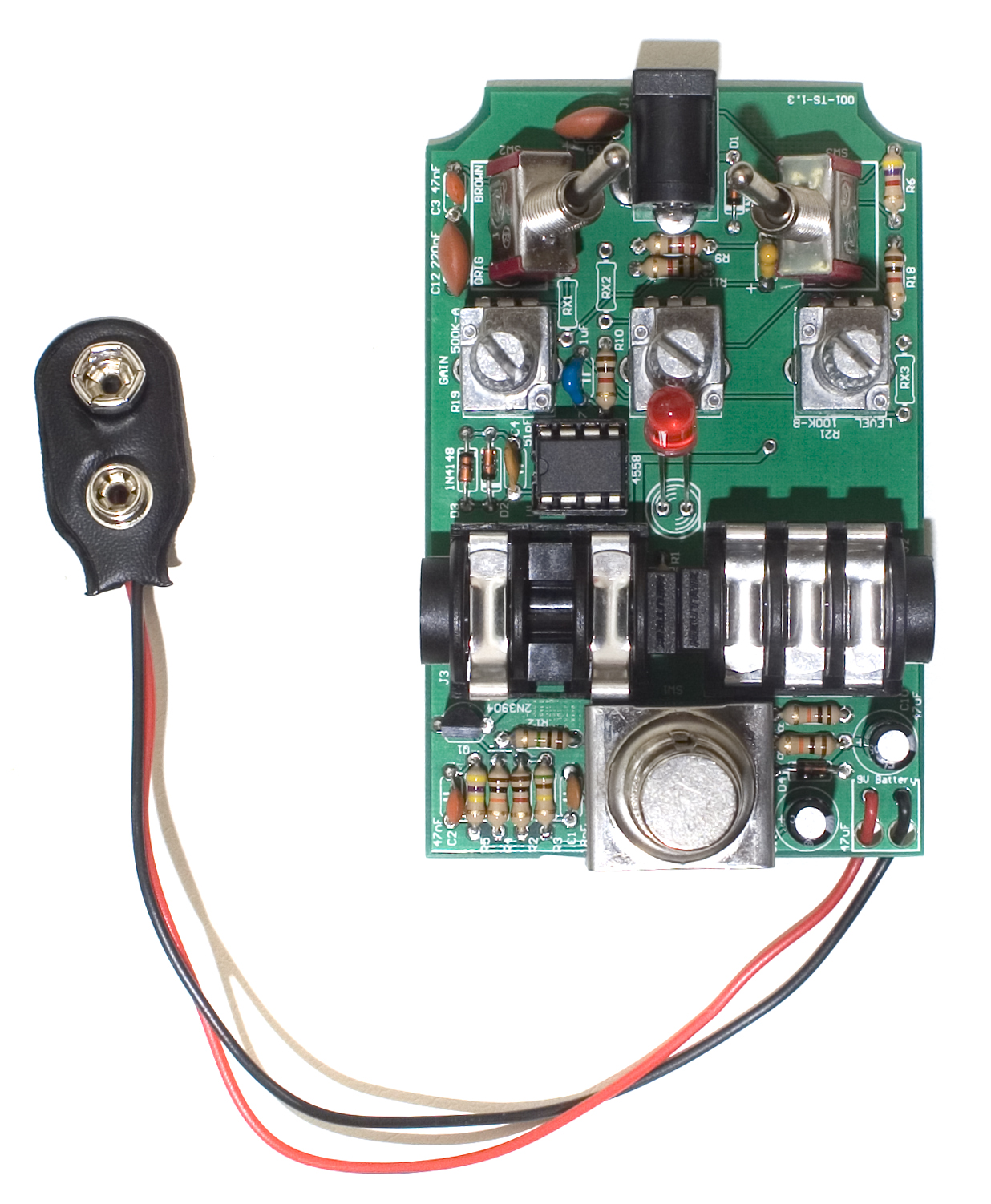
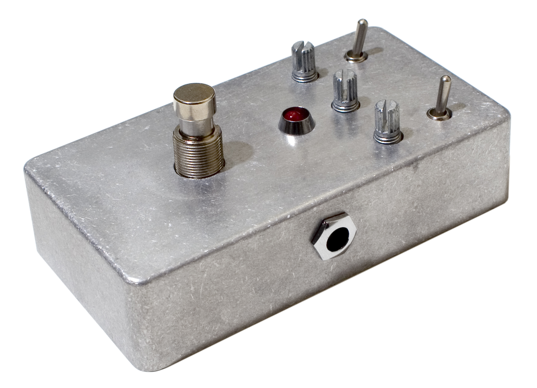
Thank you for purchasing a Mean Screamer Clone Kit. If you are looking to build this kit in a larger or different enclosure, please consult our WIRED version of this kit. Please follow these instructions in order, as it can be tricky to build and insert into the enclosure.
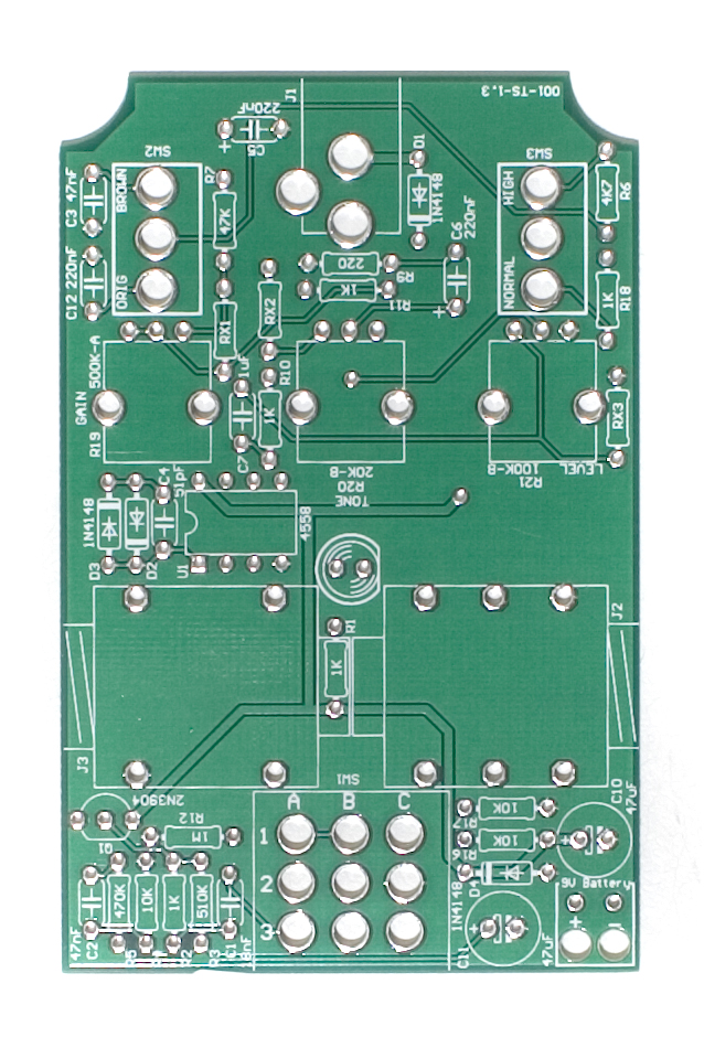
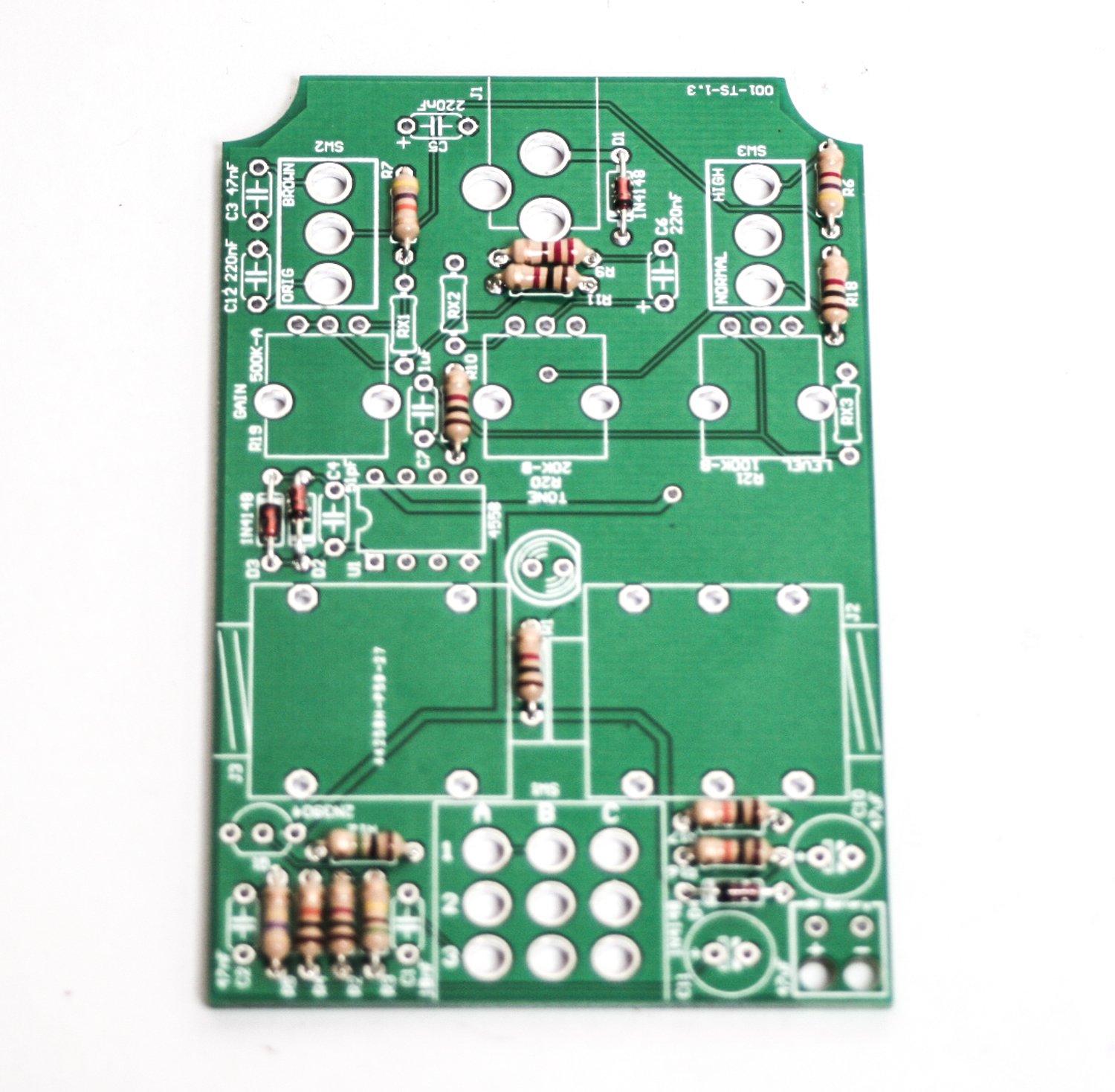
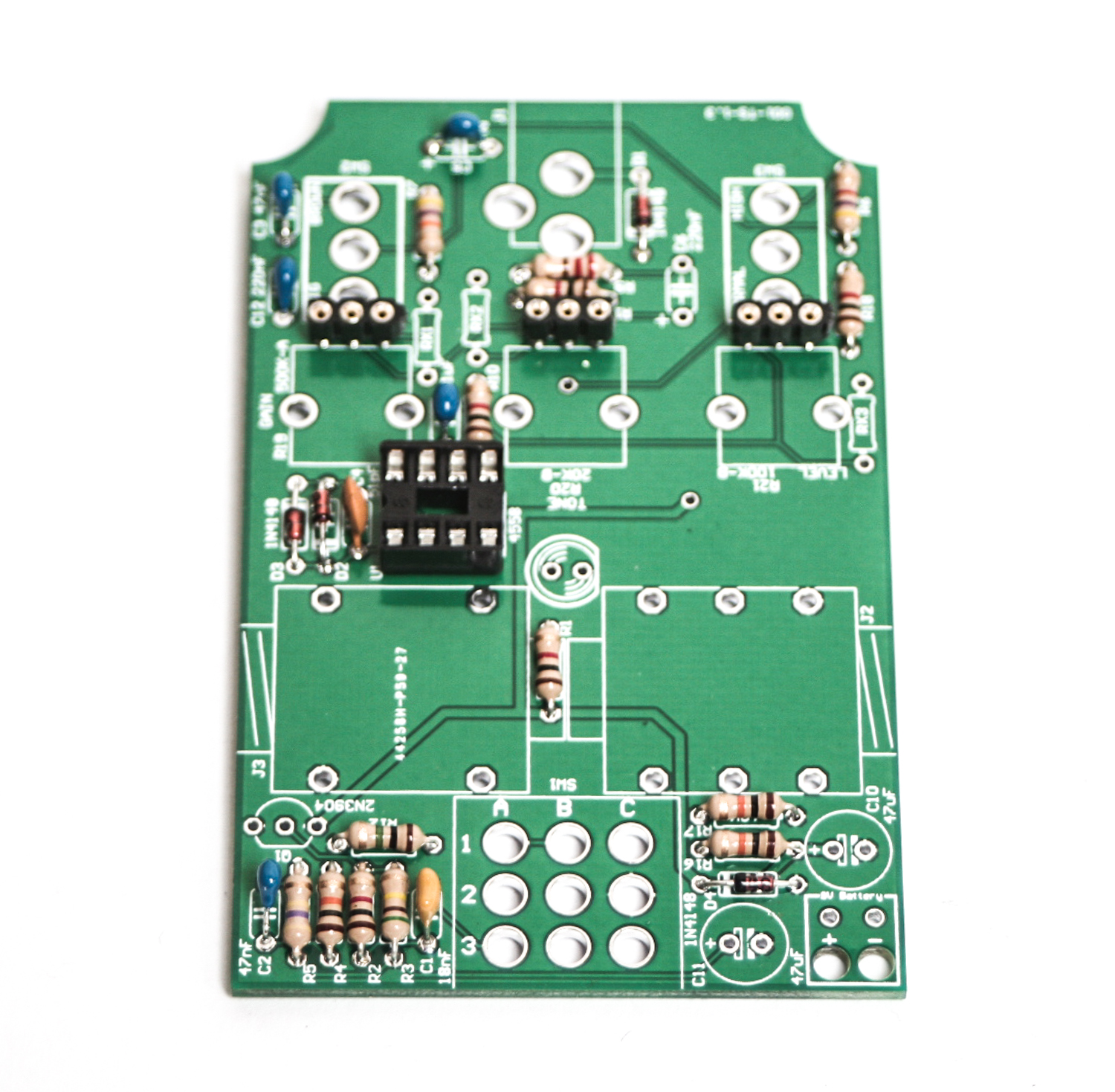
RESISTORS & DIODES
Please consult the BOM prior to adding any component. While we try to keep the same looking components in stock, variations of appearance will happen. Do not rely on the photos alone. If you need help reading components, check out our resistor and capacitor code charts in the menu at the top of the page.
Diodes are polarized components, make sure to match up the stripe on the diode with the stripe on the PCB when populating these.
3 PIN SOCKETS
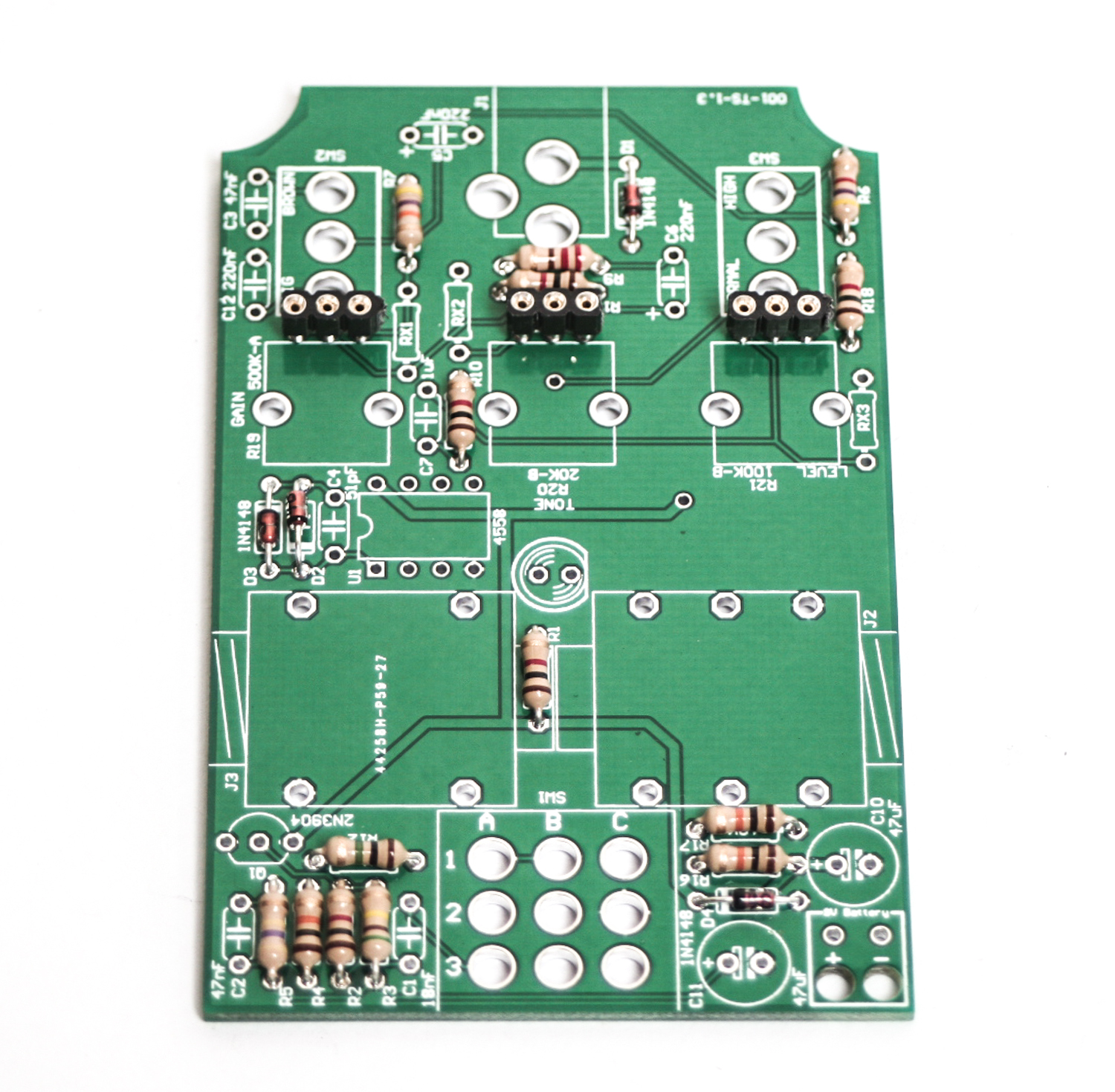
Resistors, Headers and Diodes
Some kits include a taller pot and do not need these sockets. Now place the 3-pin metal headers in as shown above and carefully flip the PCB over and solder them into place. Notice that there is a plastic black sleeve that holds the header pins together. DO NOT overheat these while soldering as they will melt and be harder to use. If you are having trouble keeping them in the board when you flip it over, you can use a little piece of tape to hole them in place while soldering.
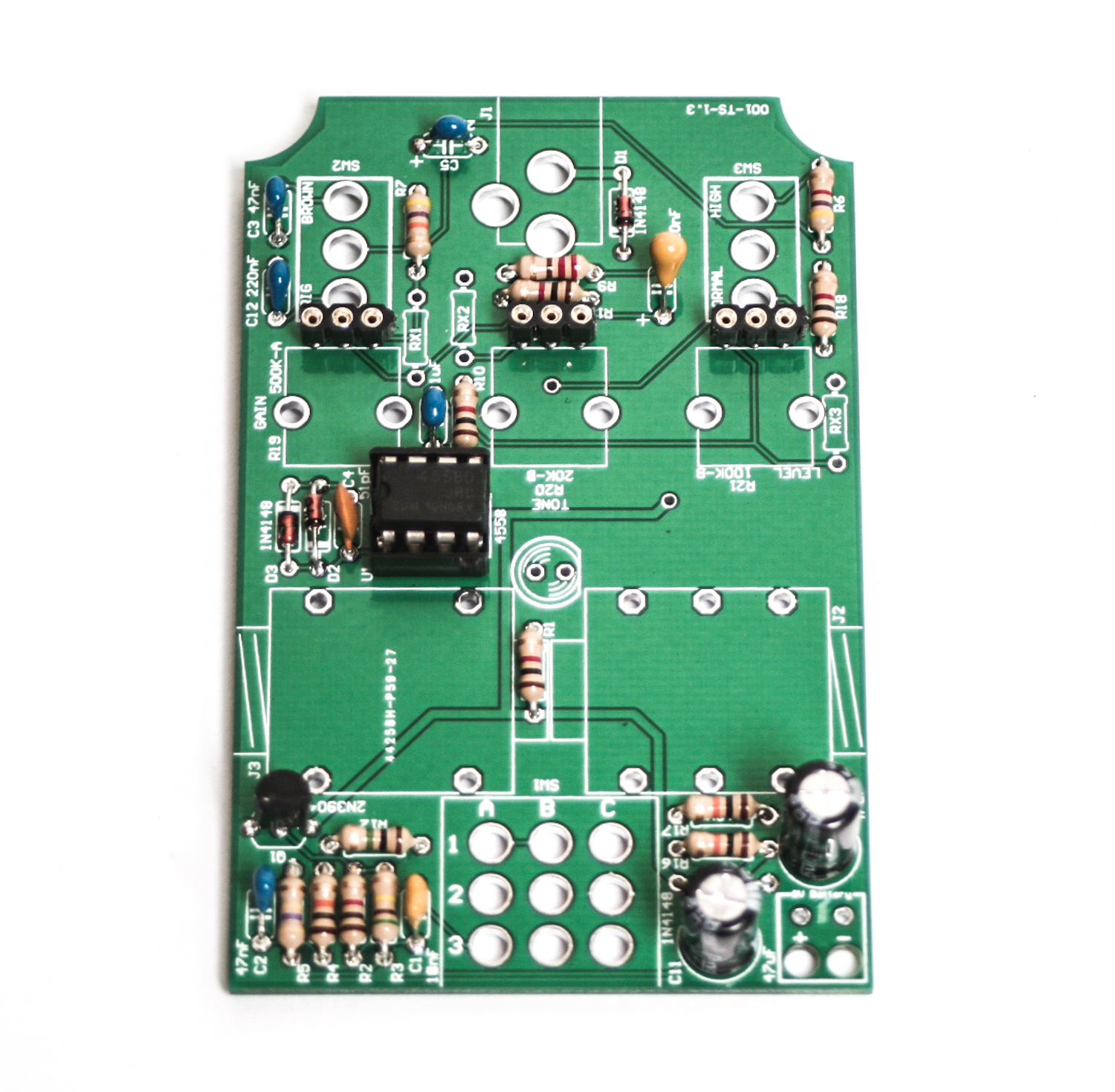
IC SOCKET
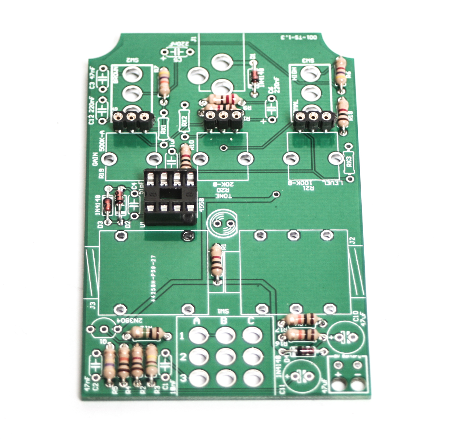
Socket
When inserting the IC socket to the PCB, align the notch with the notch on the PCB silk screen. Then turnover and solder.
Ceramic Capacitors
Now we can populate the ceramic capacitors. The ceramic capacitors are non polarized, so it does not matter which direction they face when populated. It will make any potential troubleshooting later easier if you populate them in a way that makes the code on the side easier to read.
Now carefully flip your project over and solder everything in place.
Transistor, Electrolytic Caps, DC Jack
Non-Polarized Caps
When populating the transistor, take care to line up the flat side of it with the same indicated flat side on the silkscreen, as shown in the picture above. Now carefully flip your project over and solder everything in place.
The electrolytic caps are polarized, so when inserting them into the PCB, make sure to align the longer lead with the little ‘+’ sign that is present on the silkscreen of the PCB. Once you’re happy with the placement, carefully flip your project over and solder everything into place.
Next up is the DC jack. Populate it as straight as possible, and then solder it in place. To help with getting it straight, it is recommended to solder just one leg of it (the furthest back one is easiest), and then gently apply pressure while re-heating the solder joint to guide it into place.
![]()
9v Battery Clip, Input / Output Jacks
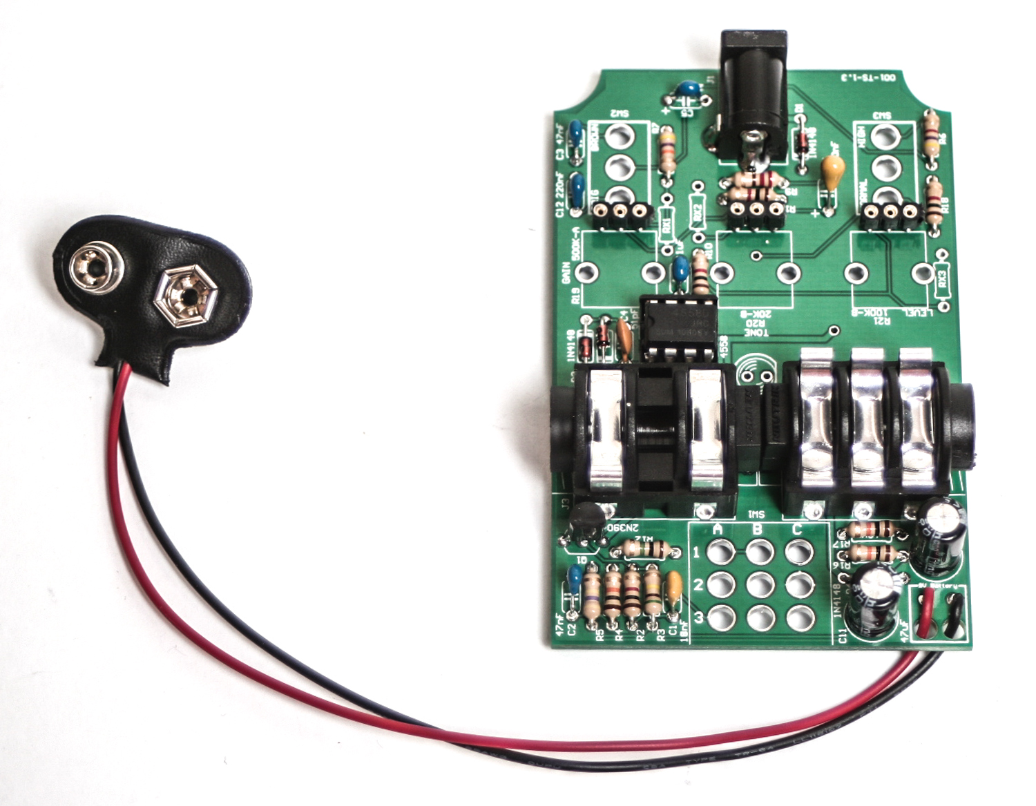
When populating the battery clip, first insert the two wires through the stress relief holes, and then insert them into the solder pads. Make sure to put the red wire into the spot marked ‘+’ and the black on into the spot marked ‘-‘. When you are happy with their placement, carefully flip the project over and solder the wires in place. Then pull any excess wire back through the stress relief holes so that the battery clip is tight, as shown above.
Now we can populate the Input and Output jacks. Keep in mind, one is stereo (input) and out is mono (output). Populate them according to the BOM, and then carefully flip your project over and solder them in place. Take your time with these, and make sure they are nice and flat to the board. When we insert this pedal into it’s case, these will be what aligns everything to the case before we solder everything down, so you want them to be nice and straight.
Case Prep
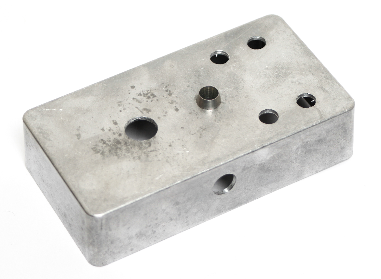
Next up, we are going to attach the LED bezel to the case. Insert the bezel through the case, and tighten the nut down on the back side.
Component Placement
Now we are going to populate all the controls for the pedal, including the 3pdt stomp switch, the potentiometers and the LED. Make sure you populate everything according to the BOM, and take care with the LED. It is polarized, so make sure that you align the flat side of the LED with the same indicated flat side on the silkscreen. When placing the 3pdt stomp switch, it should only fit one way, but make sure that the two flat sides of the base are facing the front and back of the boards.
DO NOT SOLDER ANYTHING YET!!
TRIMMING POTENTIOMETERS
Please note: Some kits include a taller pot and do not need to be trimmed.
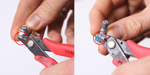
The 9MM potentiometers need to be trimmed in a few places to properly fit into this project. All 4 PCB mount clips should be cut to the base of the body of the potentiometer. Please see photos below:
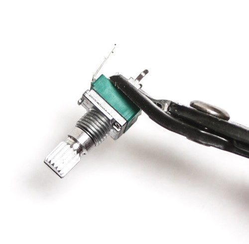
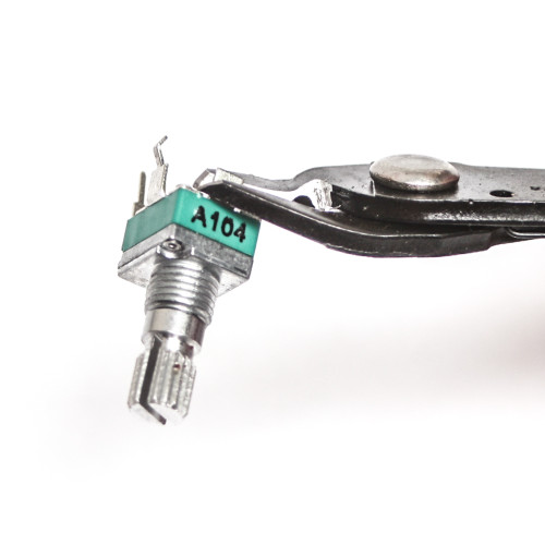
Clipping Potentiometers
Don’t forget to cut the nubs on the potentiometers if necessary.
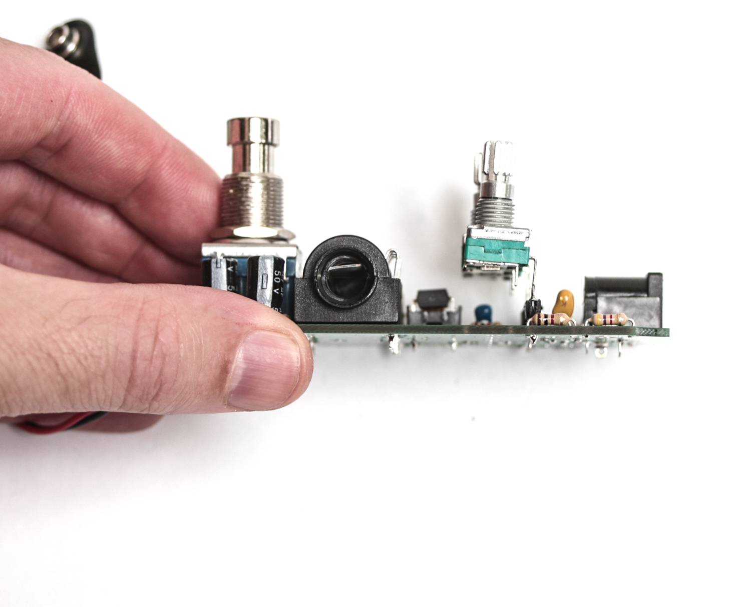
Now we want to place the trimmed pots (as shown above) into the 3-pin headers. Before you try to solder the pots to the 3-pin heads it is advisable to add a small amount of solder to one of the pins of each header first. This will allow you to align the pots on place and hold down one pin before soldering the rest. This is the best method to avoid melting the 3-pin header. After this, solder the remaining pins as shown below.
Now we want to place the trimmed pots (as shown above) onto the 3-pin headers. Before you try to solder the pots to the 3-pin heads it is advisable to add a small amount of solder to one of the pins of each header first. This will allow you to align the pots in place and hold down one pin before soldering the rest. This is the best method to avoid melting the 3-pin header. After this, solder the remaining pins as shown below.
Assembling the Pedal
THIS NEXT PART CAN BE TRICKY. PLEASE FOLLOW INSTRUCTIONS CAREFULLY.
Now we are ready to assemble the pedal. Carefully life up your un-soldered pedal and slide it into the enclosure. You may need to use a small screwdriver to help ‘guide’ things into their proper holes. When you can see the side jacks aligned with their respective holes on the side of the case, carefully insert their screws to hold everything in place while soldering.
Next, carefully put the pot washers and nuts on the shaft of the potentiometers, and tighten them only a couple turns for now. You want to tighten them enough so that the nuts have a good hold on the threads, but not so much that you pull the legs out of the PCB. Please see the picture below for proper alignment. The same is true for the switches. When trying to solder the switches in later, they may try to fall out of the pcb when you flip the pedal over. You can grab a piece of masking tape and use it to gently hold the switches down while you solder them.
Go ahead and slip the large washer over the stomp switch, and then tighten the nut down on top of that.
When you are satisfied with the alignment of everything, solder just one leg or pin of each component into place. Then double check the alignment on the top of the case to make sure that nothing is crooked. If it is, gently apply pressure to the top and re-heat the solder joint. This should seat it flat against the case. When you’re happy with the alignment of everything, finish soldering everything in place.
Final Assembly
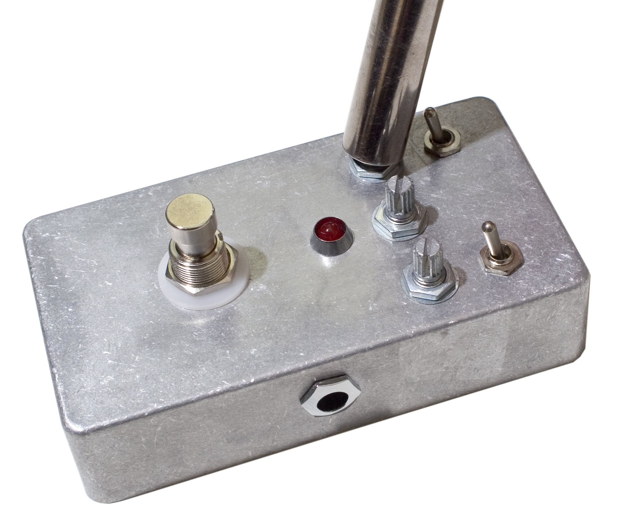
At this point, everything should be soldered in place, and ready to go. Grab your trusty socket (or wrench/pliers/fingers) and tighten the nuts all the way down. Make sure not to over-tighten them, as you can damage the components! Then you can put the knobs on top of the pots, and tighten them down as well.
Before putting the back on the project, it is recommended to test out your pedal and make sure everything works. That way if you need to check something or re-flow a solder joint, you can get to most of them easily.
CONGRATS!
You have assembled your Mean Screamer and are ready to shred. If you have any issues after putting the project in a case, carefully remove it and look for a connection that could have broken and repair.
BE SURE TO USE ONLY A 9V CENTER NEGATIVE POWER BRICK OR A 9V Battery.
Are the places on the board labelled RX1, 2, and 3 places for potential mods or are they just part of the board design?
Thanks!
They are part of the design and are not to be populated.
In the picture where he is actually soldering the pots, the leads do not seem to be trimmed as much as the picture above it might suggest they should be. Is the general idea simply to cut the narrower part of the leads?
Hi Rob, the small part of the pot leads should be trimmed in half, so there is still half of the smaller part (not the total) remaining.
Hi steve, i was wondering if/how I could replace the 3PBT switch with a standard switch as I want to mount the board directly into a cigar box guitar I am building?
Hey, if you are just wanting to replace the stomp switch with a toggle, they offer a 3PDT toggle on this page, part number is M302. If you don’t use a 3DPT, you wont get true bypass, and we don’t have instructions on how to go about doing that.
-Patrick,
Synthrotek
Hi guys, I accidentally soldered the wrong component in C4 and in an overzealous attempt to remove the component (without a solder sucker, it’s broken) have seemed to have burned/damaged one of the holes for the component. The damage is on the hole further from the printed “C4” on the board.
As a fix for this I was wondering if I could be able to just bridge the connection with some wire to the next component, in my mind this would be D2 on the same side. Is any of this correct?
Hi Christian, these things happen from time to time. You can just follow that trace and ad use some wire to make the damage connection.
Looking at the q1 opening near the cluster of resistors near the bypass switch. Is this to be populated with a variable resistor or a triode? I’m lost right now.
Hello, Q1 is a 2N3904 transistor. If you need info on any other callouts, you can view the BOM here.