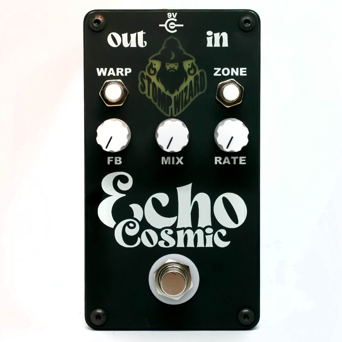
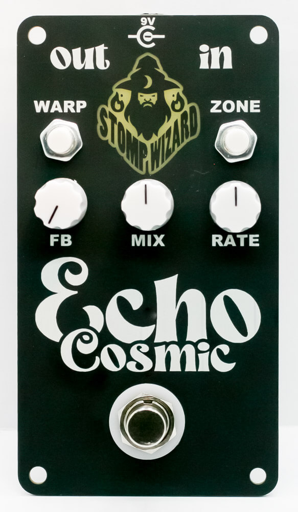
Stomp Wizard Cosmic Echo Assembly Instructions
Thank you for purchasing the Stomp Wizard Cosmic Echo! This is an easy to intermediate build. All the components are through hole, and there’s no ground plane, which makes it much easier to build than your average circuit.
If you feel like you can handle it, please proceed! If not, get some help from a friend with experience or purchase a fully built pedal.
Please build according to the BOM, and not these instructions or the pictures alone. Some components may have changed since these were written, or we may not be able to get the exact components in the pictures.
Notes before starting
- Tools and supplies necessary for the build:
– Soldering iron (we recommend an iron with a base station and a fine tip)
– Solder
– Snips
– Mini flat head screwdriver
– 2mm or 5/64″ Allen/hex key - Hang onto the masking tape that holds the resistors/caps/etc. At the end of the build, if you aren’t using the 9V battery connector, you will need to tape the terminals on it to prevent a short.
- J3 is not populated in this circuit, but it allows for an expression pedal to have control over the Rate knob. It just needs to be wired to a 1/4″ mono jack. We use this on the Cosmic ECHO Squared pedal. We don’t provide instructions on modding the Cosmic ECHO for the expression pedal jack, but if you wanted to drill out the case or the panel, you can fit a 1/4″ jack where the battery normally goes.
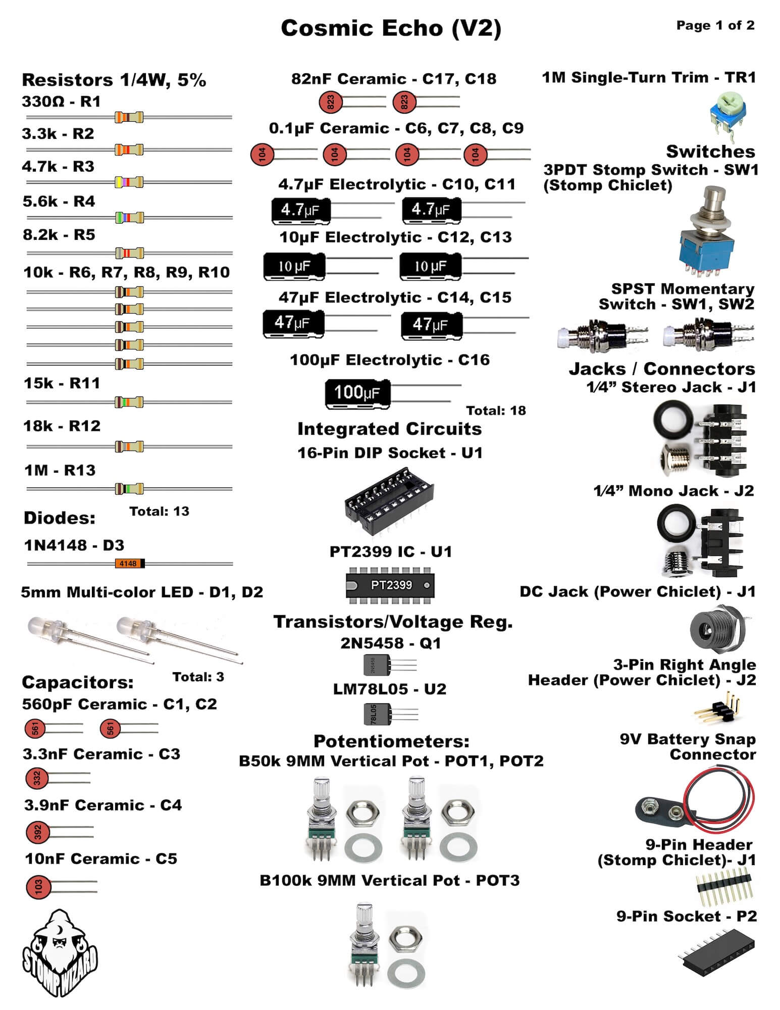
For a bill of materials with a Mouser parts list, click here.
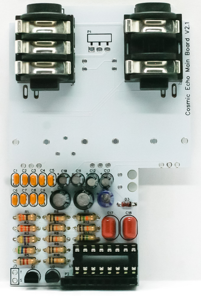
Diode
Remember that diodes are polarized components. Make sure to match the stripe on the diode to the stripe on the PCB. Turn over to solder then clip the excess leads.
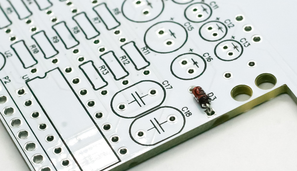
Cosmic Echo – Diode
Resistors
Resistors are not polarized, so place them in the PCB either way. Turn over to solder then clip the excess leads.
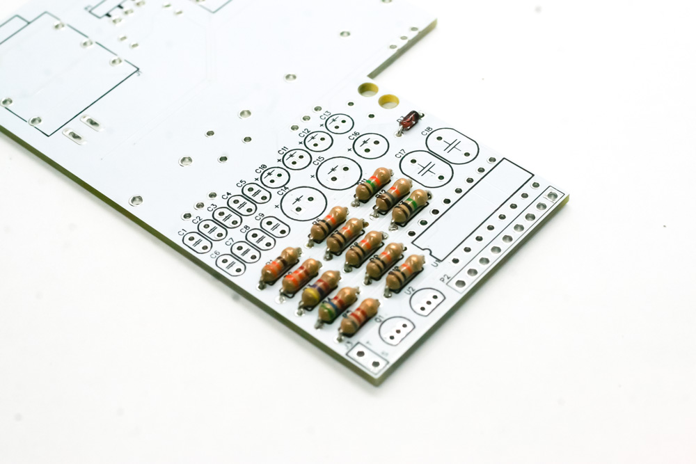
Cosmic Echo – Resistors
IC socket
Next place the IC Socket into place and solder on the back side of the PCB. Make sure you align the notch on the socket with the notch in the PCB silkscreen. Turn over carefully to solder.
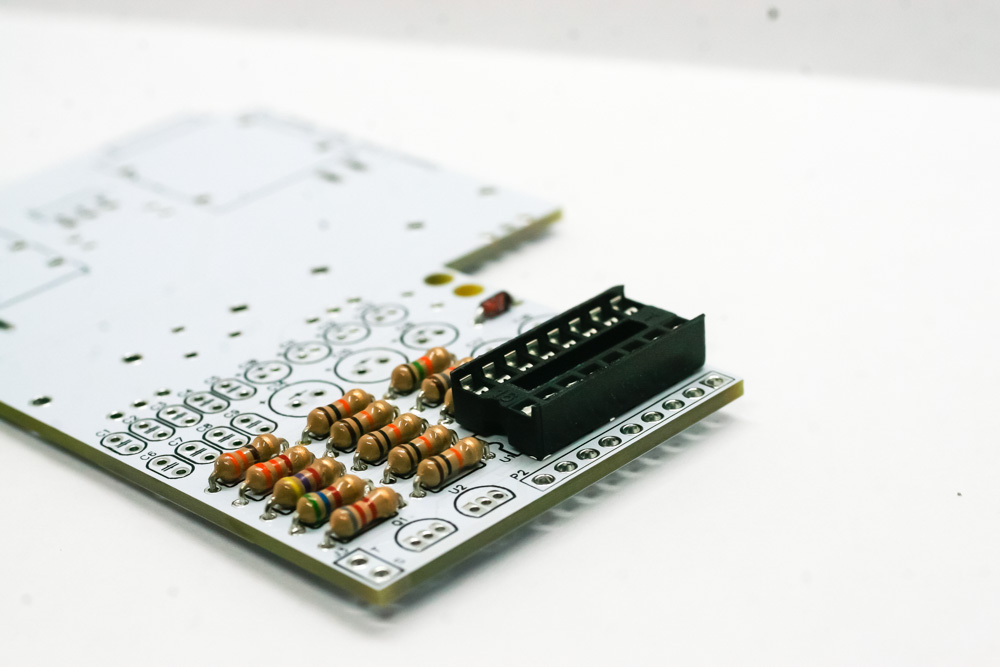
Cosmic Echo – IC Socket
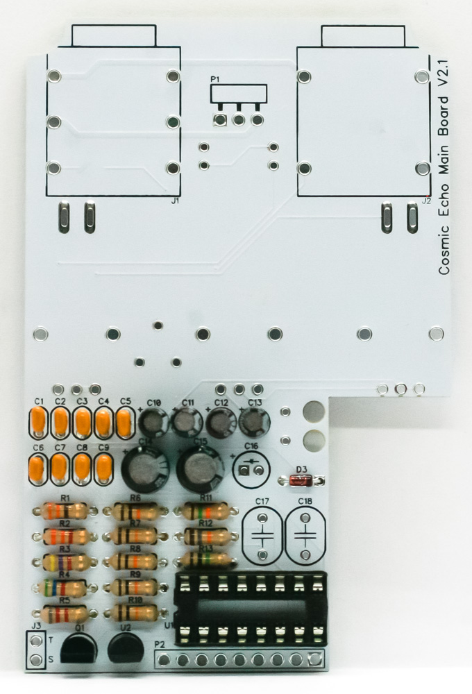
Electrolytic capacitors
Next, populate the electrolytic capacitors by lining up the longer lead (anode) with the ‘+’ marking on the PCB. Place all the electrolytic caps except for C16. Solder, then trim the excess leads.
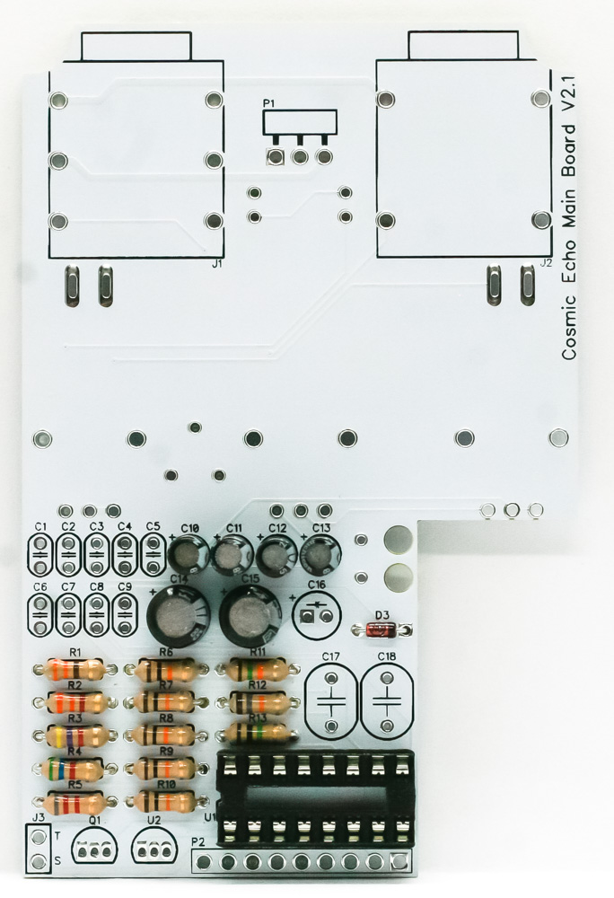
Cosmic Echo – Electrolytic Capacitors
Transistor / voltage regulator / ceramic caps
The transistor & voltage regulator are polarized components. Align the flat side of the components with the flat silkscreen graphic. The ceramic caps are NOT polarized, place them in either way. Leave out C17 and C18. Carefully turn project over and solder in place. Trim the excess leads.
Cosmic Echo – Transistor / Voltage Regulator
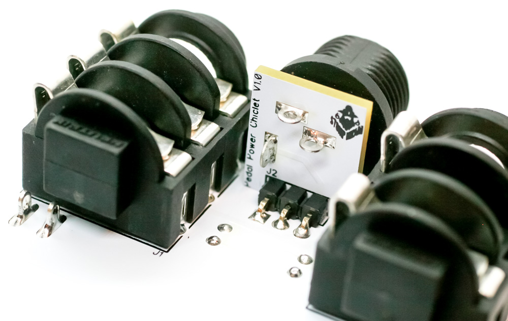
Remaining capacitors, socket and audio jacks
Place the remaining electrolytic cap and the two remaining ceramic caps (C16, C17, and C18) into the PCB. Solder and clip the excess leads.
Next, place the 9-pin socket into the PCB; solder one pin and make sure it’s both flush with the board and perpendicular to the board (if not, reflow that solder joint and reposition it). Once it looks good, solder the rest of the pins.
After that, place the stereo and mono jacks into the PCB as shown below. Solder one pin on each jack and make sure they are flush with the PCB. Once they are flush, solder in the remaining pins.
Cosmic Echo – Remaining caps and jacks
Trimmer
Place the trimmer into the PCB as shown below. (Note: the silkscreen may show it on the other side, but orient it as shown in the picture.) Turn over and solder in place.
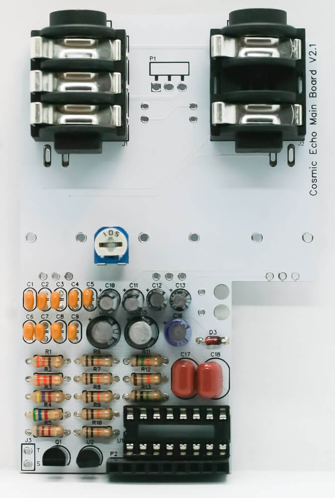
Trimmer
LEDs
Place the two LEDs into the PCB by aligning the flat side of the LED with the flat side of the silk screen. When done correctly, the longer lead will be inserted into the hole that has the “+” marking near it. Turn over to solder in place and clip the excess leads.
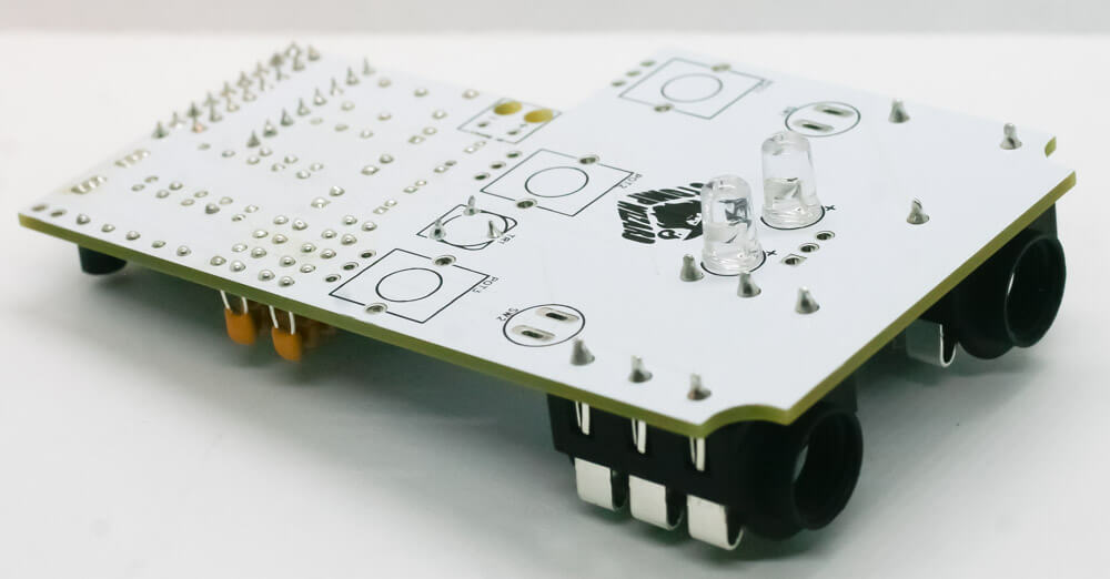
LEDs
9V battery snap connector
Thread the red wire through the strain relief hole and connect it to the “+” hole. Do the same for the black “-” wire. Solder up!
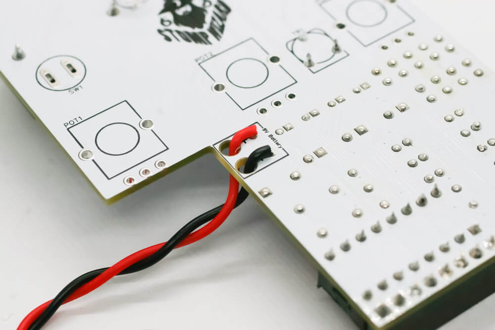
9V battery clip wired to PCB
DC jack
Place the right angle header pins into the PCB as shown below. Solder one pin, then check to make sure the plastic pin housing is flush with the PCB (if not, reflow that solder joint and reposition it). Once it looks ok, solder in the other two legs.
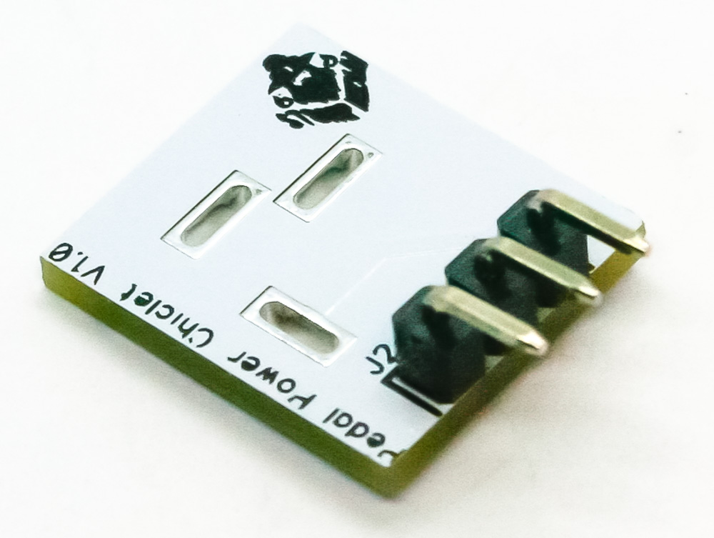
Cosmic Echo DC jack PCB
Place the DC jack flush into the PCB as shown below. Solder up!
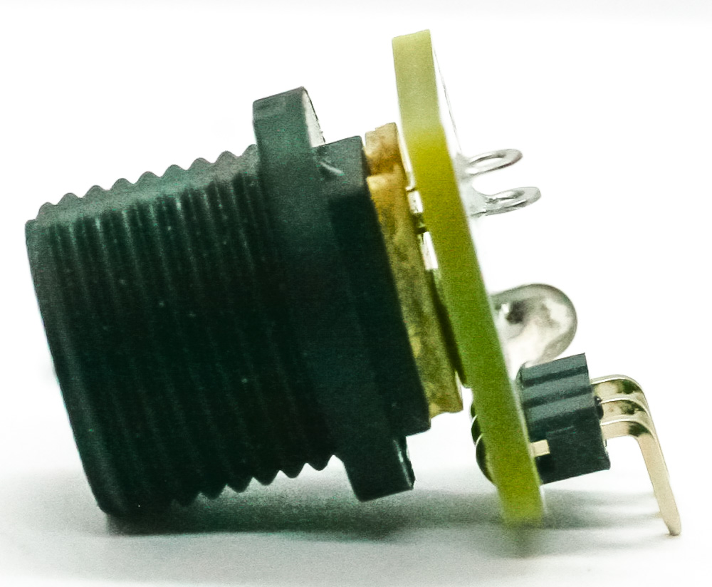
Cosmic Echo DC Jack 2
Now connect the DC jack PCB to the main PCB. Solder in one leg and make sure it’s flush with the main board and at a 90 degree angle from the main board (if not, reflow that solder joint and reposition it). Solder in the other two legs.
Cosmic Echo DC Jack Install
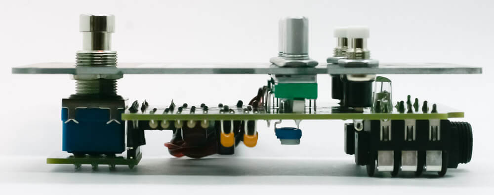
Potentiometers and momentary pushbutton switches
Place the potentiometers and pushbutton switches into the PCB as show below, BUT DO NOT SOLDER JUST YET.
Cosmic Echo Push Potentiometer and Pushbutton Switches
Place the panel over the project and finger-tighten the nuts onto the shafts of the buttons and pots. Solder in the pots and the buttons.
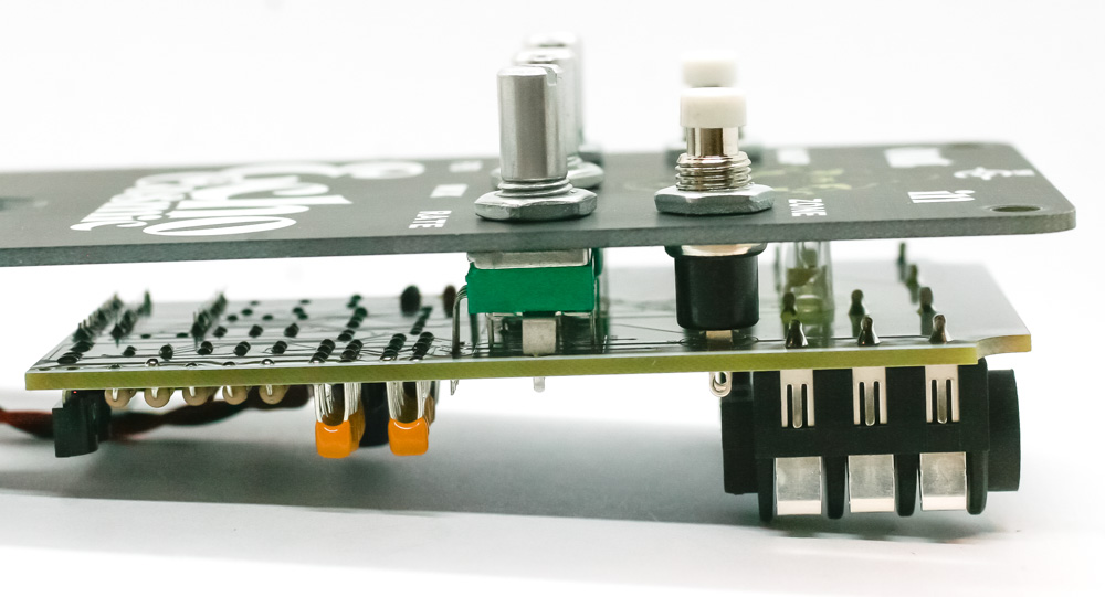
Cosmic Echo Button Placement
Stomp switch PCB header
Place the 9-pin header into the PCB as shown below and solder in place, making sure it is both flush with the board and perpendicular to it.
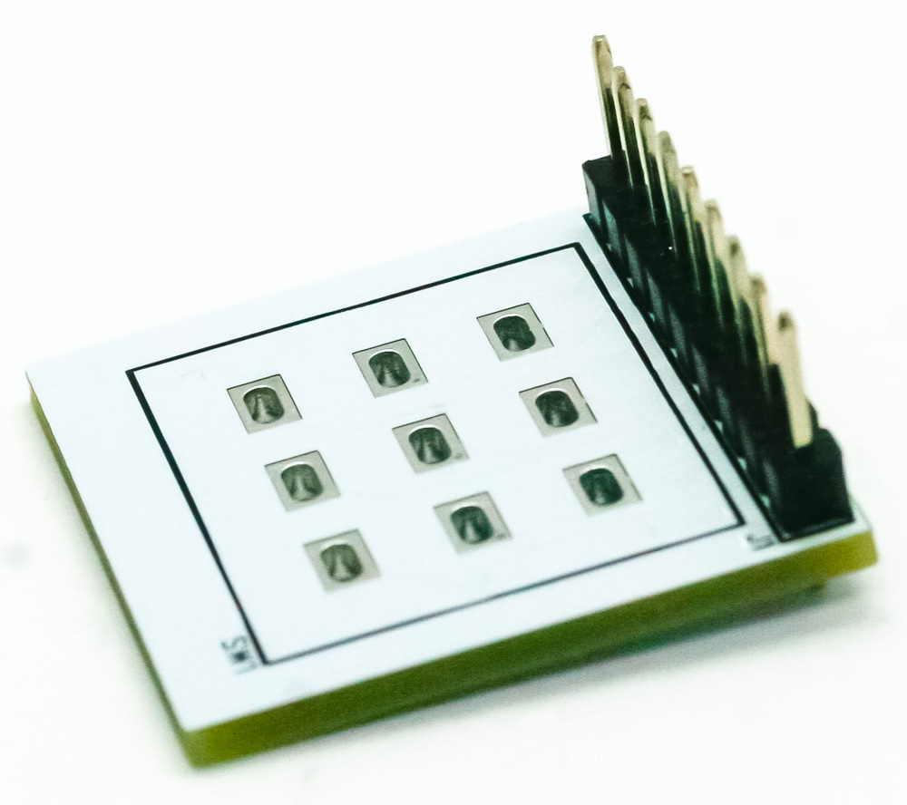
Cosmic Echo Stomp Switch PCB
Insert the 3PDT switch so that it is flush with the PCB as shown below and solder it in.
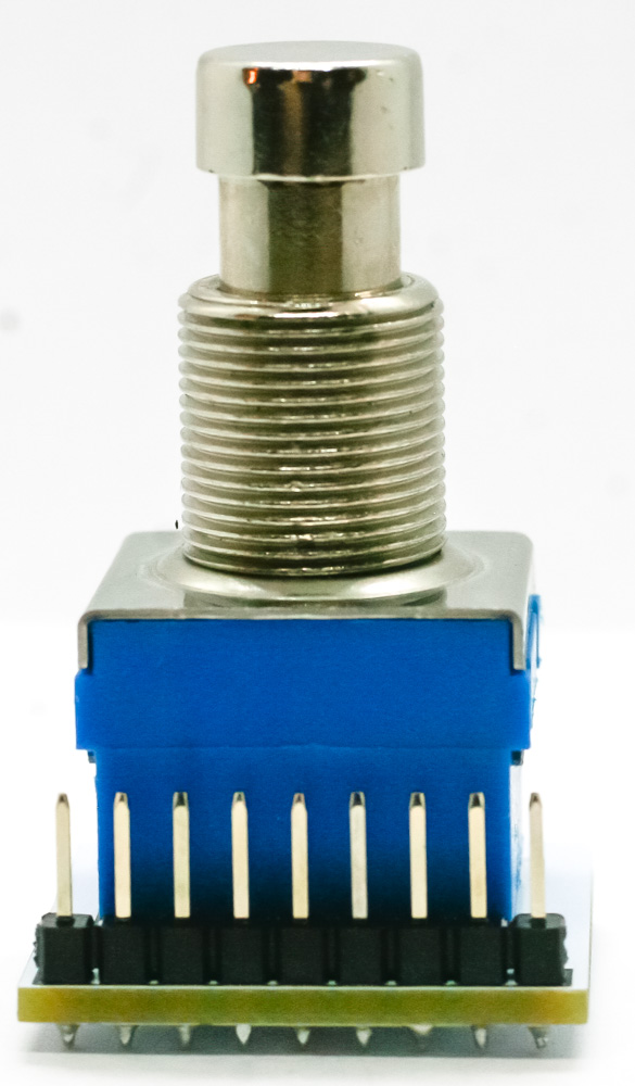
Stomp Switch
Stomp switch nut
Thread a nut onto the 3PDT switch, most of the way down the shaft. Connect the 3PDT PCB to the main board. Move the nut upwards, against the underside of the panel, so that the nut is level with the pots and momentary switches on the main board.
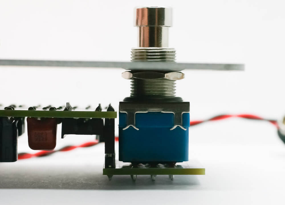
3PDT nut up against panel
Level with pots and switches
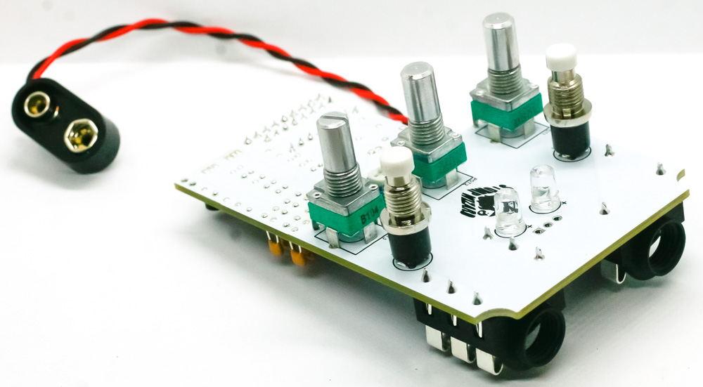
Panel Assembly
Place the white washer and nut on the top side of the 3PDT switch. Gently tighten down the nuts on the stomp switch, pots, and switches.
Put the knobs on the pots and tighten them down with a mini flat head screwdriver.
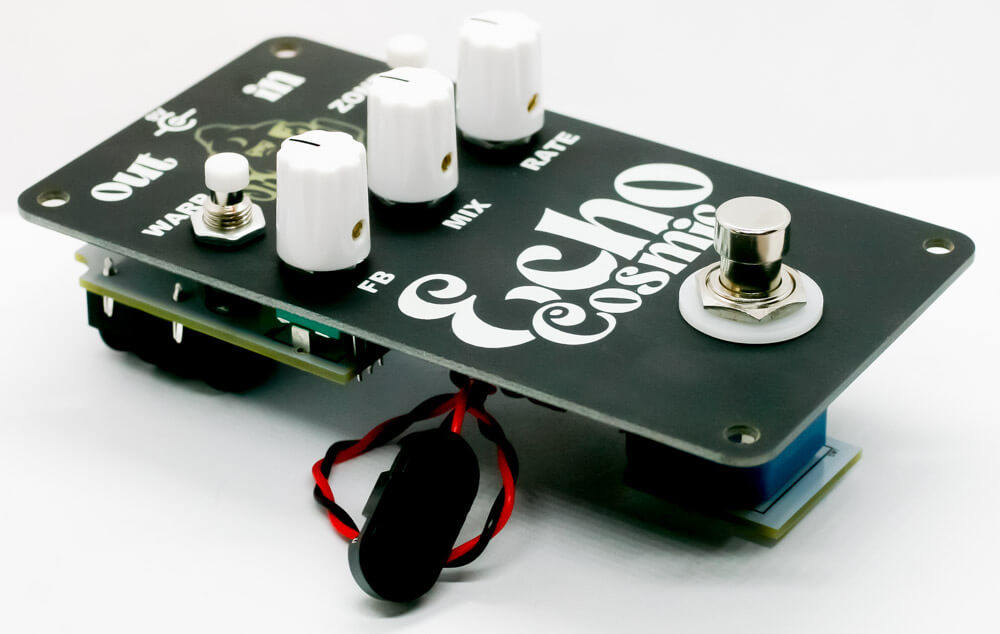
Fully assembled with knobs on, not in case yet
PT2399 IC
Bend the legs of the IC inwards on both sides slightly by pressing them against a hard surface. The legs should be bent enough so that they fit in the socket, but not so much that they are curled under the IC like a dead bug.
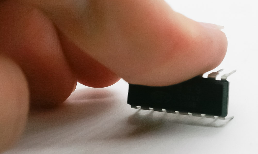
IC leg bending
Insert the IC into the socket so that the notch in the IC matches the notch on the silkscreen.
Make sure that none of the legs are bent while it’s being put in. If you do bend a leg, use a pair of tweezers to carefully pull the IC back out and straighten the pin.
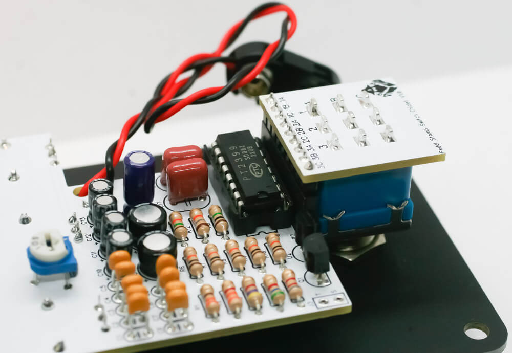
IC in socket
9V battery
If you are using a battery, connect it now. If not, put a piece of masking tape over the battery terminals so that they don’t cause a short.
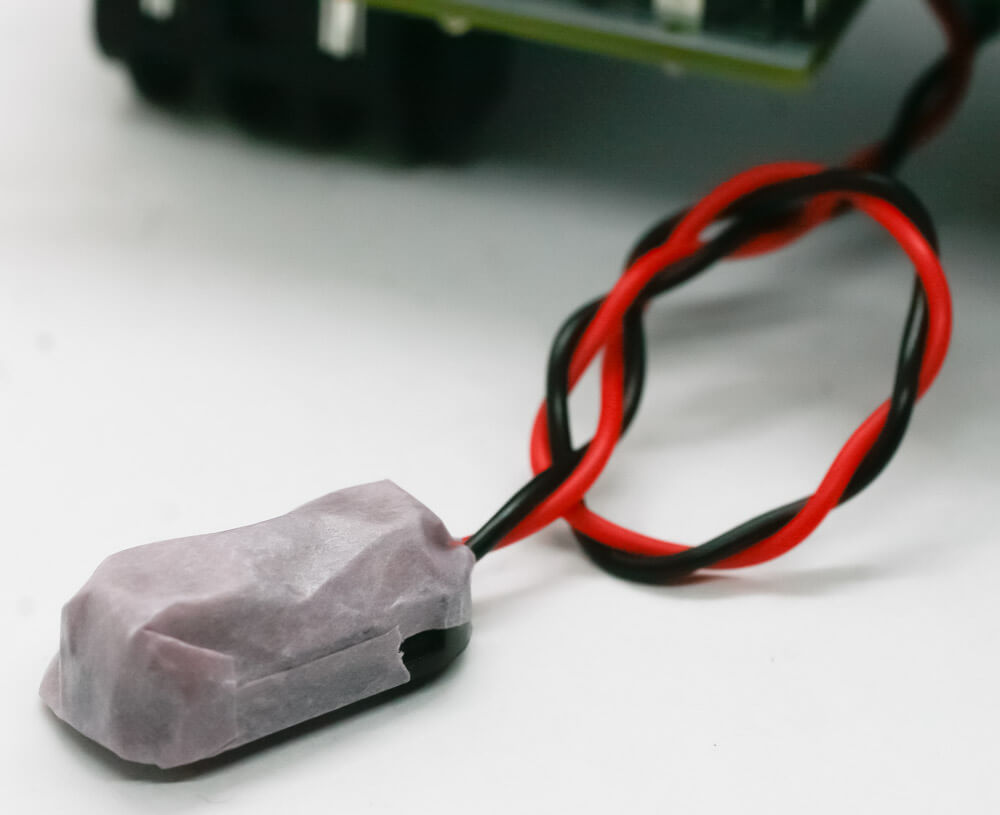
9V battery clip taping
Initial test
Set the circuit on a non-metallic surface. Use a 9V battery or plug a 9V center negative power supply into the DC jack. It’s ok if both a battery and the DC jack are plugged in at the same time; if they are, the power will draw from the DC jack to save battery life. Also, note that the pedal won’t power on unless a 1/4″ jack is inserted into the output jack (this helps to keep the battery from draining when the pedal is not plugged in).
Plug an instrument into the pedal, and the pedal into a speaker.
Check all the pots/buttons/switches (except the Zone button) to make sure they are changing the sound. Should be pretty spacey!
Zone trimmer adjustment
The Zone button injects extra feedback into the audio. The amount of feedback it injects will change depending upon how the Feedback and Mix knobs are set. You won’t hear an effect when the feedback is cranked up high, but you will hear it when there’s no feedback or a moderate amount of feedback.
The trimmer is set to taste, but here’s a good place to start:
Set the knobs:
– Feedback: fully counter-clockwise
– Mix and Rate: 12 o’clock
Setting the knobs to adjust the Zone
Using a flathead screwdriver, adjust the trimmer (TR1) on the PCB fully clockwise.
Now push and hold the Zone button. You should hear a little bit of feedback injected into the circuit. Rotate the Feedback and Mix knobs a bit, and adjust the trimmer to taste.
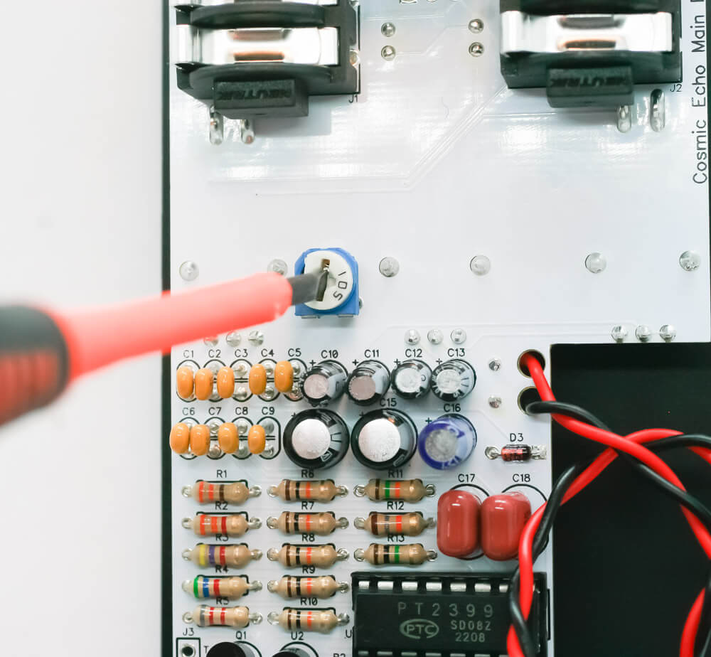
Adjusting trimmer with screwdriver
Final steps
Unplug your cables and carefully place the project into the case. Thread on the audio jack nuts and DC jack nut, but don’t tighten them down yet.
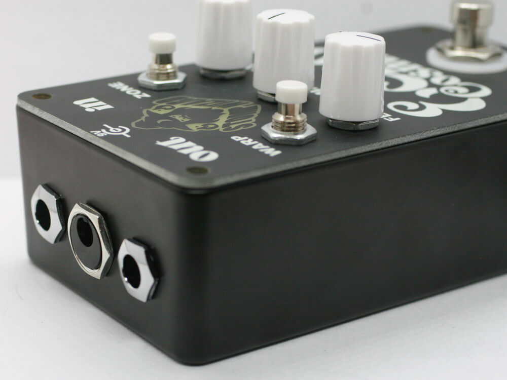
1/4″ and DC jack with nuts
Add the hex screws through the panel and into the case. Use a 2mm (or 5/64″) Allen/hex key to tighten down the screws. Now tighten down the audio and DC jack nuts (finger-tight is ok).
That’s it! Get ready for some ECHO!