


Important Links
Product Page
Store Page
Assembly Instructions
Bill of Materials
Schematic
Capacitor and Resistor Lookup Guide
Welcome to the assembly instructions for the Modular ECHO delay effect circuit (formerly known as the EKO). This circuit is designed to accept either Eurorack or Fractional Rack standard power connections.
BOM Layout
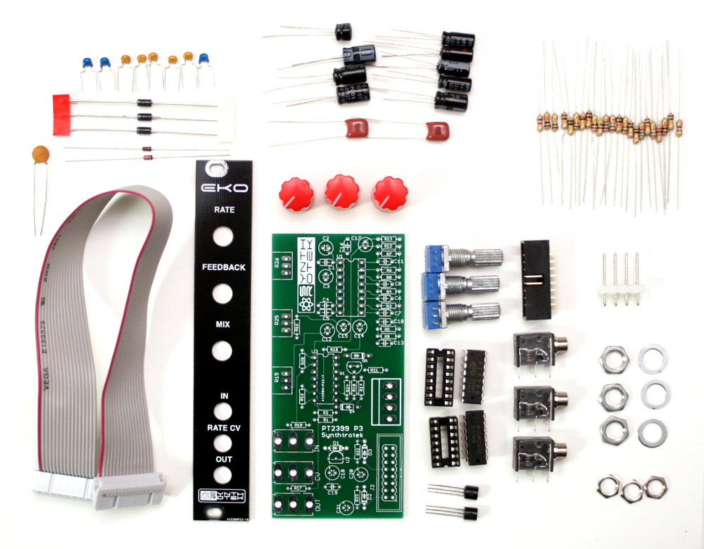
Modular ECHO Parts
If you’ve received your parts and ready to build, the first thing you should do is to check to make sure you have all the parts. Check your kit against the Modular ECHO BOM. If you’re missing anything we’ll send it to you free of charge.
Soldering the Components
Attention: Changes may occur after the Assembly Instructions are created and the photos may not reflect those changes. Always use the BOM to verify the placement of components.
Resistors and Diodes
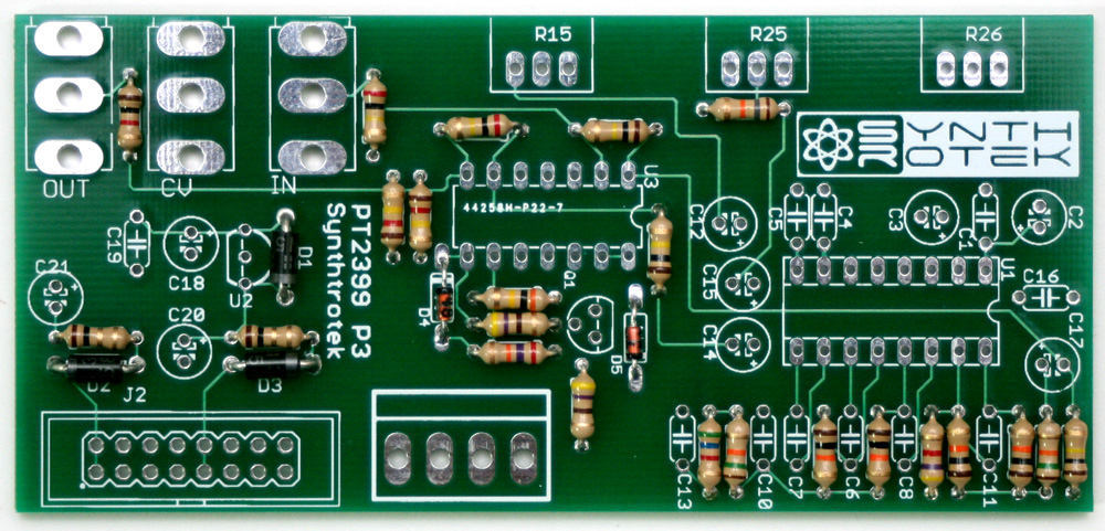
ECHO Assembly Step 1: Resistors and Diodes
First solder all the resistors and diodes into place. Ensure that the line on the diode matches with the line on the PCB silkscreen. Resistors are not polar sensitive so you may install them in any orientation.
Capacitors
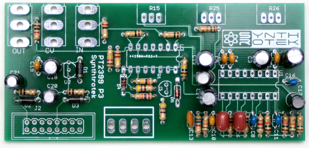
ECHO Assembly Step 2: Capacitors
Now solder all the capacitors. The electrolytic capacitors are polar sensitive. Make sure that the longest lead from the electrolytic capacitor goes into the hole marked with the plus (+) sign. The ceramic capacitors are not polar sensitive and can be installed in any orientation.
IC Sockets and Transistors
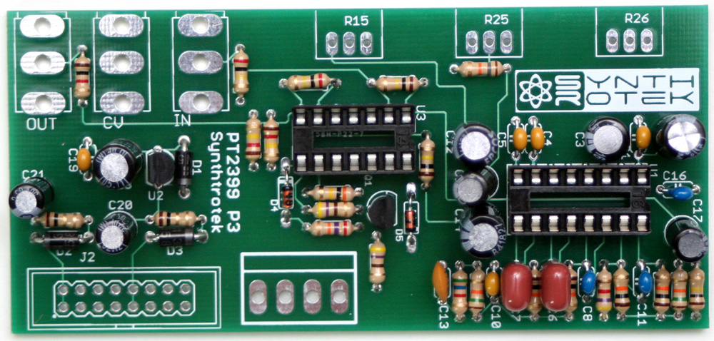
ECHO Assembly Step 3: Transistors and IC Sockets
Now lets install the transistors and the IC socket. You need to align the flat side of the transistors to the image of the flat side on the PCB silkscreen. For the IC socket, make sure that the notch on the socket matches with the notch in the image on the PCB silkscreen. A tip for soldering the IC socket flat to the PCB, first solder two opposite corners of the socket and then make sure that you get the socket flush to the PCB. Afterwards solder the rest of the pins and touch-up the two first pins as necessary.
Potentiometers
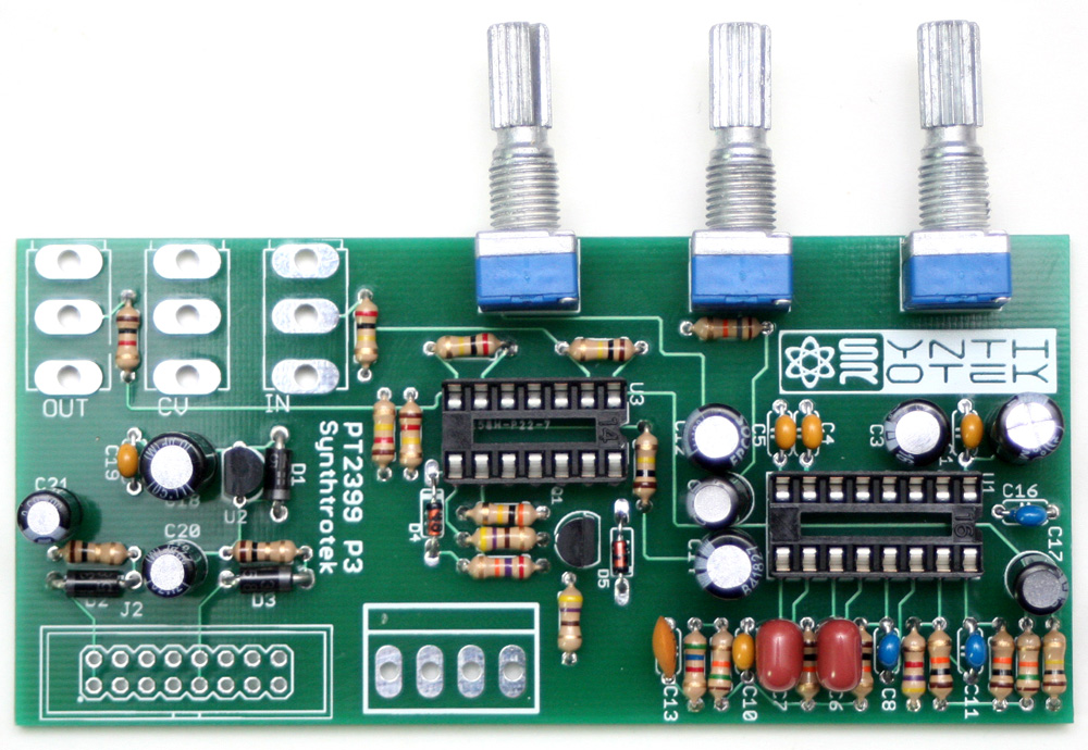
ECHO Assembly Step 4: Potentiometers
Now you can install the potentiometers. You can use a similar trick as with the IC socket to make sure that the component is flush to the PCB, just solder a single center-pin or two pins on opposite sides first and make sure that the component gets flush to the PCB, and then solder the rest of the pins.
When installing the pot, some pots come with nubs near the shaft that may get in the way of installing the circuit into a case. Check for a nub and clip as necessary.

Don’t forget to cut the nubs on the potentiometers as neccesary.
Jacks and Connectors
Eurorack Power
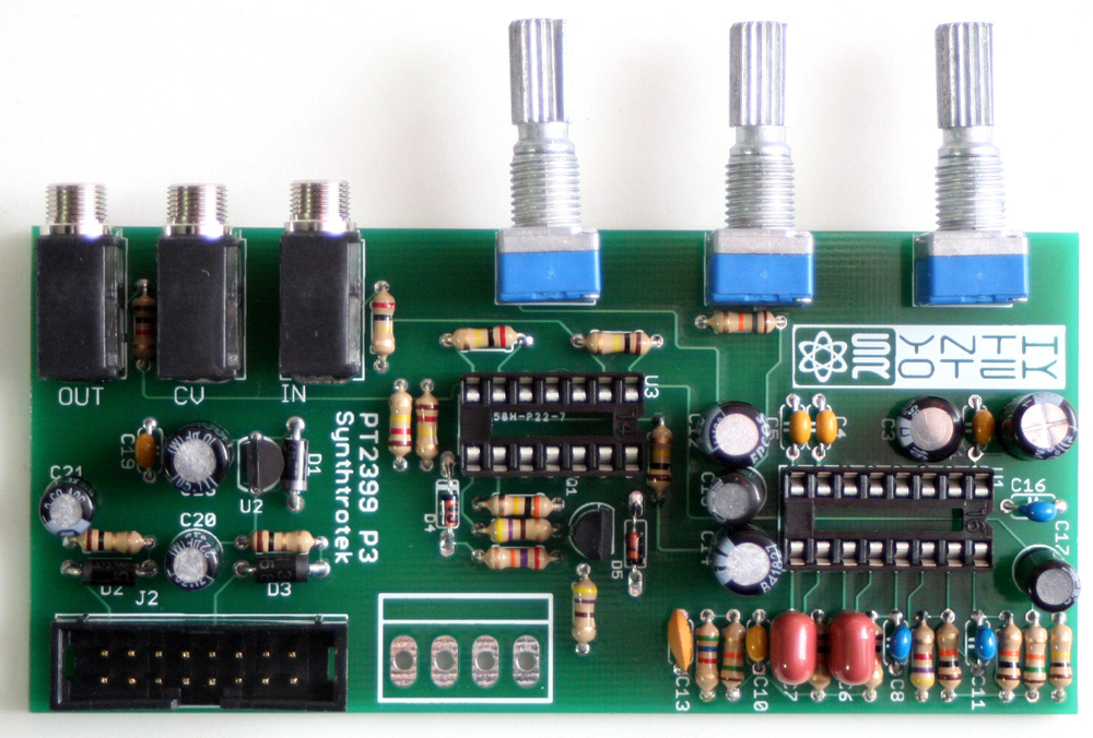
ECHO Assembly Step 5: Audiojacks and Eurorack Power
Fractional Rack Power
ECHO Assembly Step 5: Audiojacks and Fractional Rack Power
We are almost done with soldering! Get those audio jacks in and then, depending on if you ordered the EuroRack version or the Fractional Rack version you will only have the 16-pin shrouded header or the 4-pin molex. Match the connector to the image on the silkscreen, ensuring that the notch on the 16-pin header is aligned with the image of the notch on the PCB, or ensuring that the 4-pin molex connector latching mechanism is aligned with the image on the PCB. Again, you can use a similar trick as with the IC socket to make sure that the component is flush to the PCB before soldering it completely to the board.
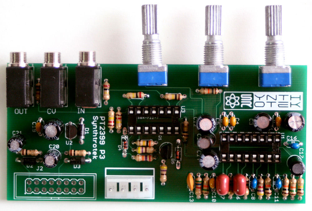
ICs, Panel, and Knobs
ECHO Assembly Step 6: ICs, Panel, and Knobs
Now you just need to install the ICs into their appropriate sockets, making sure to align the notch on the IC with the notch on the socket, and then you’ve got a functional ECHO circuit!
If you got the Eurorack version you will also get a Eurorack panel. Attach the panel to the circuit with the nuts provided. To avoid scratching the panel when tightening the nuts we suggest either using rubber tipped tools or simply wrapping the ends of your tool with electrical tape.
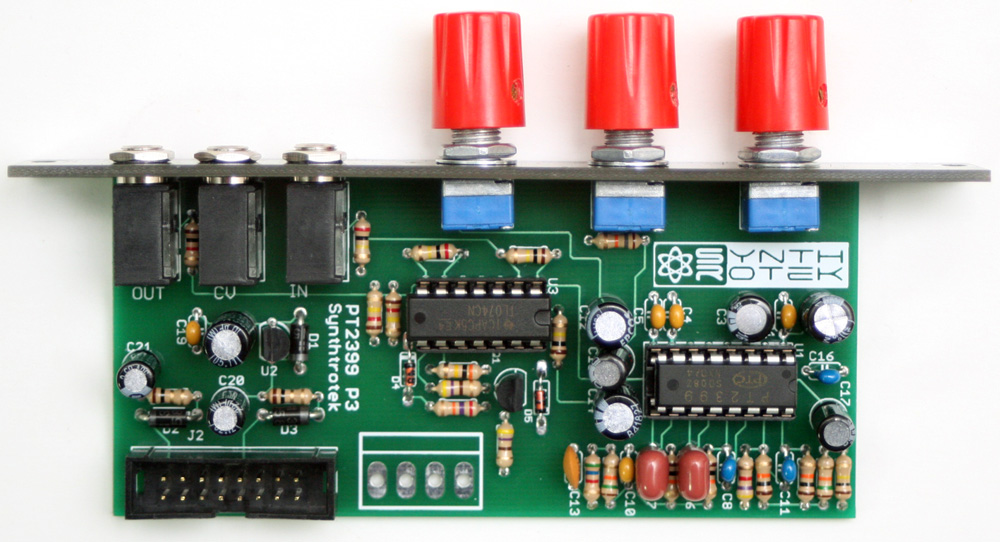
Finalized Circuit
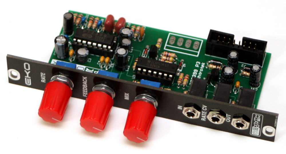
ECHO Assembly Finished
Testing Procedure
—CHECKING FOR FEEDBACK—
First thing to check is if the ECHO will self-oscillate. Set the RATE knob fully counter clockwise, set the FEEDBACK knob fully clockwise, and set the MIX knob fully clockwise. The ECHO should now be self-oscillating.
—CHECKING THE DELAY RANGE—
Just like you did above, set the DLY up to self-oscillate. Slowly turn the RATE knob clockwise until the delay goes as slow as possible before “getting weird.” That’s usually about 1.13 seconds of delay before the delay will start to become glitchy / erratic. You will notice the delay cutting out before the RATE knob is turned fully clockwise. This is normal!
—TESTING INPUTS—
Set all knobs to noon and take an audio source (preferably non drone based) and plug it into IN. Make sure that the audio is passing through and is being delayed.
Take a Bipolar (-5/+5V) Envelope, LFO, Offset, or Sample & Hold and plug it into the RATE CV input. You should be able to hear the speed of the delays change from fast to slow and vice versa.
By now you should be able to confirm that the ECHO is working correctly.
Congratulations! You just successfully just built a ECHO module from Synthrotek!
This was a quick, simple build and sounds great – and only 4hp!
Can the Warp, Feedback, and Feedblast Mods be done on this version ?
While it should be possible, we haven’t done it ourselves, and have no plans to try this mod with the Eurorack Echo
The BOM seems to be incorrect. It states 23 resistors but only 22 are needed. Location R11 is missing from the board. Also for location R18 the BOM states a 47k but the picture shows a 100k? Which is it? Does it matter?
Thanks!
Fred,
R11 is definitely needed for the circuit to work, the silkscreen for it is just below R25, the middle potentiometer. As for R18, please follow the BOM on that value, as we changed it in a recent revision.
Best,
-Patrick
Thanks for nice kit. My first kit. All working. Great instructions to build. There was wrong potentiometers in my kit (placement was vertical not horizontal to pcb). It took time to the pcb.
Thanks!
Hey Andrius,
I’m so sorry we got you a kit with the wrong parts, we can send you the right stuff out so it can be fixed, if you want. I’m glad you got it all soldered up without issue. Shoot us an email at store@synthrotek.com, and we can arrange getting you the right parts.
Best,
-Patrick
if we had to use our own parts, is it required to have stereo jacks? or would mono be acceptable.
Hi,
So i’m still trouble shooting this build from before my last inquiry in July ^^ since i still haven’t received any response. I noticed in the schematic that pins 2 & 3, the ring and tip, are connected. So how is this supposed to work if we only have TS cables since in this case, all 3 (Tip, Ring, Sleeve) would be connected??
What is the most important difference between echo and delay? Thank you!
Hey Chris,
The biggest difference is that the DLY has trimpots instead of fixed resistors at the points which determine the “rate” and “feedback” ranges, giving you a bit longer delay times. Which for PT2399 delays, tends to give you more of the overclocked sample rate reduction aka “glitch”
Thanks,
Michael