


Congrats on getting your Synthrotek Eurorack Power Distribution Kit. Below are some simple instructions on how to populate and solder your PCB properly. When you open your package of parts, please be careful to do this safely and carefully, as to not loose any parts. Check your parts against the Bill of Materials before you begin. MAKE SURE YOU FOLLOW THESE INSTRUCTIONS CAREFULLY! Errors in following instructions can result in power supply damage/failure and/or module damage/failure.
Below is a photo of the parts that you should have in your kit.
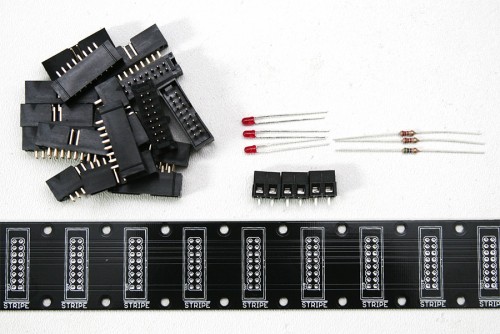
Eurorack Power Distribution Kit Materials
Assembly
Attention: Changes may occur after the Assembly Instructions are created and the photos may not reflect those changes. Always use the BOM to verify the placement of components.
First align the 3mm LEDs properly by following the photo guide below:
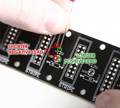
Eurorack Power Supply Distribution PCB LED align
Next, place the resistors and wire connectors into their proper place and solder them to the PCB. The connectors supplied with the kit are optional if you would like to solder your hook-up wire directly to the PCB.
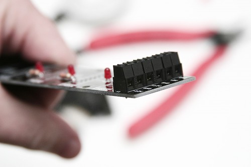
Power Distribution Connectors
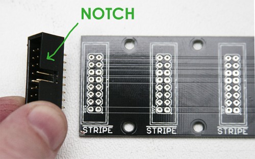
Place your 16-Pin Shrouded and Keyed Headers into the PCB as shown below. If you put these in backwards you could risk damaging your power supply and modules. Make sure you match the notched key on the header with the notch on the PCB silk screen as shown below
Solder the 16-pin header pins from the back of the PCB. Be careful not to solder any of the pins together.
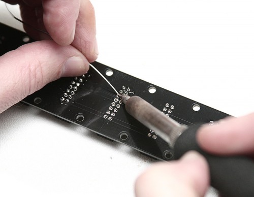
Soldering the Eurorack 16-pin header pins
After Soldering the Headers your project should look like this
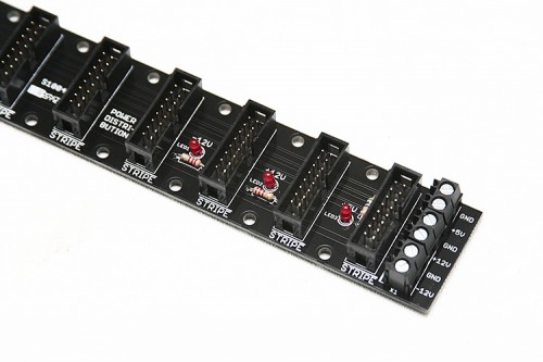
Completed Eurorack Power Distribution Board
Make sure you pay close attention to the voltage rail silk screen on the PCB when connecting your distro board to power. !!Doing this incorrectly can damage your power supply and/or modules!!
Once you connect power to the Distribution Board you should see the LED light-up for each rail that you connected properly. If an LED does not seem to work, you may have connected an LED backwards. Otherwise, plug your modules in properly and enjoy!