


Congrats on getting your Synthrotek Momentary/Latching Pass-through Switch. Below are instructions for putting together your kit. This device will allow you to either momentarily pass-through a signal with the push-button or use the switch to allow a latched pass-through. Pictured below is a photo of all the parts needed.
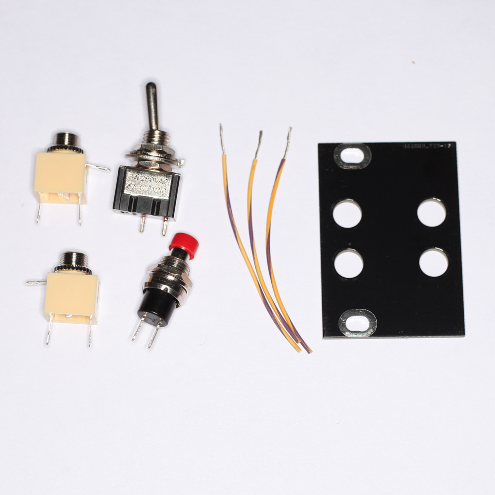
All the parts needed for this project
Got everything? Great! Lets get started.
Assembly Instructions
Prepping the Panel
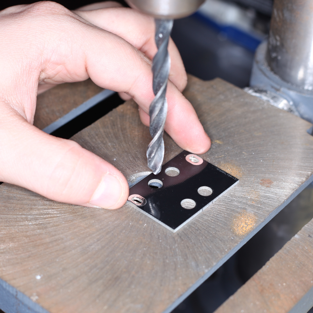
Drilling Momentary Switch Hole
First, because the momentary switch will not fit, you will need to drill out the hole in the panel to fit the switch. Make sure when drilling the PCB that you have proper ventilation and eye protection to protect against fiberglass particles.
For the momentary switch you will need to use a 9/32″ drill bit. While wearing protection, drill out the hole shown in the photo above.
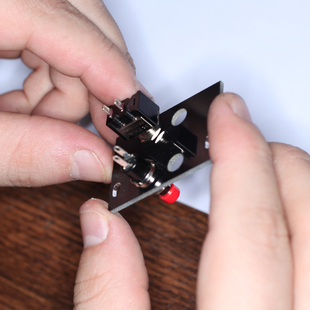
Installing the Switches
Now that the momentary switch will fit in the panel, install the switches as shown above. We recomend to orient both switches exactly as shown above, this will make wiring the components later on much easier.
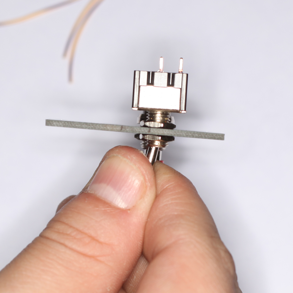
Make sure the switches are tight and flush against the PCB
For the latching switch, you can make it so the switch does not stick out of the front of the panel as much by moving the bottom nut up a few threads and leaving enough threading for the top nut. Make sure that the switches are tightly secured on the panel.
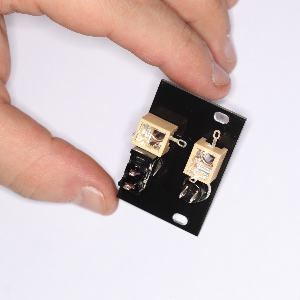
Installing the jacks
Now install the two jacks in the remaining holes. Again, orienting the jacks exactly as shown in the photo will make wiring the components together significantly easier.
Wiring and Soldering
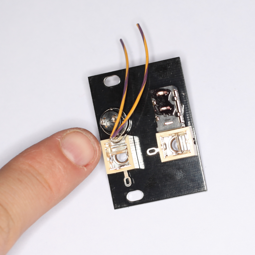
Install two wires to the jack next to the momentary switch
Now install two wires into the tip connection for the jack next to the momentary switch. Solder them into place.
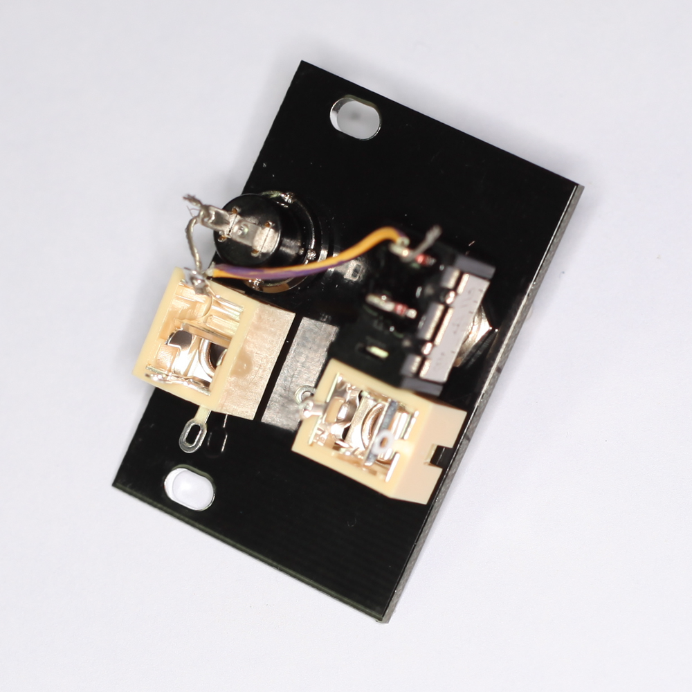
Connect the wire to the switches
Now run one of the wires from the jack to one of the pins of the momentary switch and the other wire to one of the pins of the latching switch. Cut the wires down so that there is not a lot of excess wire wiggling around, but don’t make them so short that the wires are strained between the connections. Solder the wires down once they have been placed.
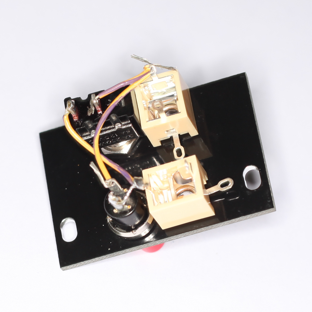
Connect the 2nd pins of both switches to the tip pin of the other jack
Now we are going to repeat what we did for the first jack to the second jack and the second pins on both switches. Start with the tip-pin on the second jack, soldering that in place, run the wires to the empty pin on the switches, again making sure that there is not a lot of excess wire to wiggle around but that it’s also not strained between the connections, and then solder them down.
Project Complete
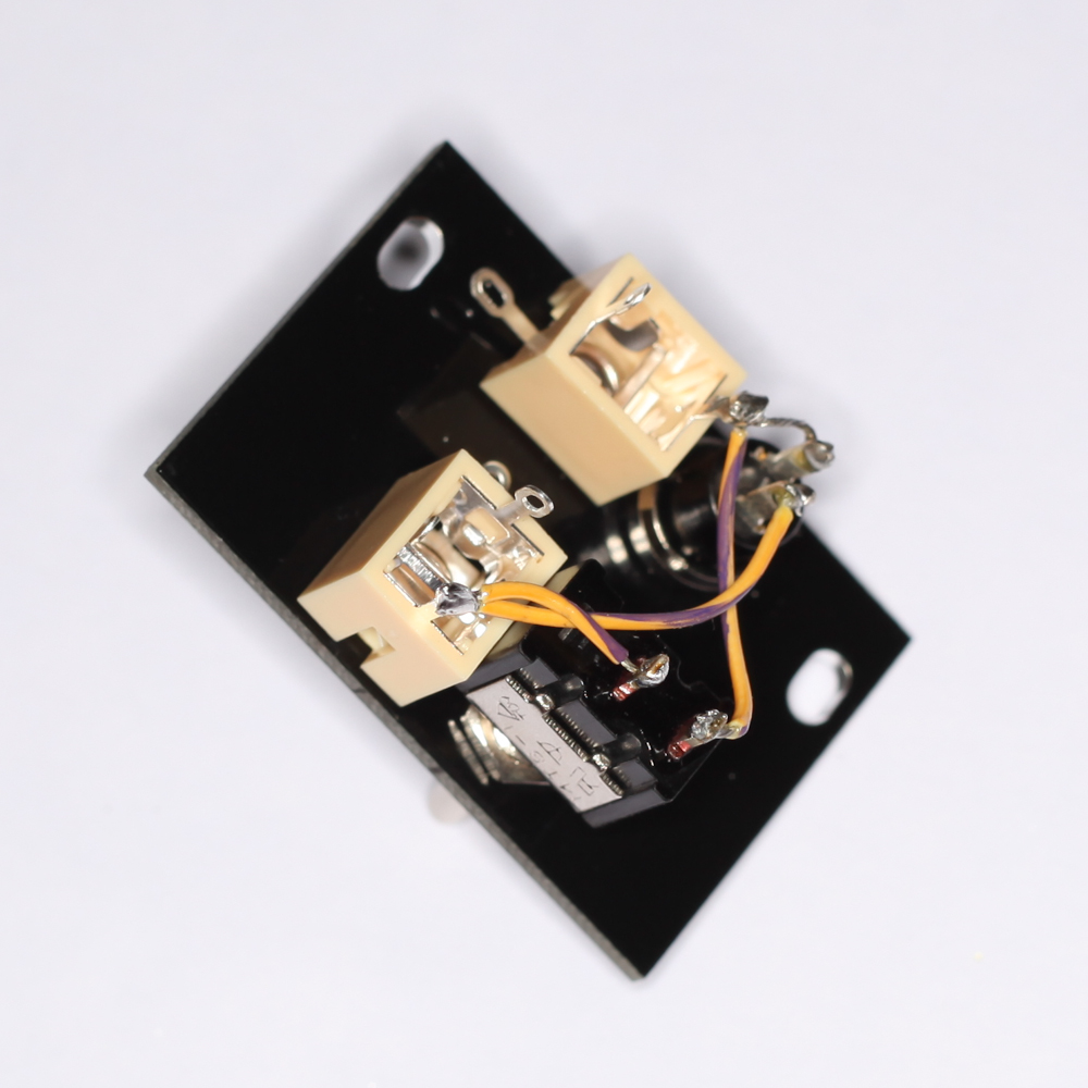
The final wiring should look something like this
And that is it. This is what the final wiring should look like.
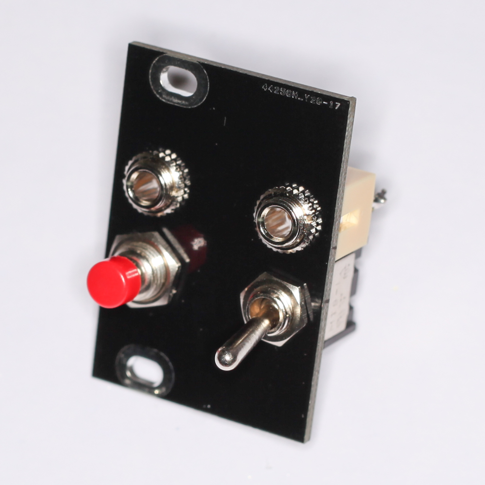
Finalized Momentary/Latching Pass-Through Switch
You’re good to go!
so then the other 2 open jack tips go to ground correct?
No they do not, if you follow the instructions you should see they are left unconnected.