


Important Links
Product Page
Store Page
Quick Start Guide
Assembly Instructions
Bill of Materials
Capacitor & Resistor Lookup Guide
Thank you for purchasing the Synthrotek APC HANDHELD kit! This is an easy to intermediate build. It is very important to get all the components properly soldered into the PCB in the correct placement. If you feel like you can handle it, please proceed! If not, get some help from a friend with experience or purchase a fully completed unit.
Please build according to the BOM, and not these instructions or the pictures alone. Some components may have changed since these were written, or we may not be able to get the exact looking components in the pictures.
Diode and Resistors
The diodes are polarized, so make sure to populate them with the cathode stripe in the same direction as indicated by the silkscreen. Once everything is in place, carefully flip your project over, and solder the components in place. Clip any excess leads on the bottom of the board.
Resistors are non polarized, so it doesn’t matter which direction you put them on the PCB, but it will help with any troubleshooting that may arise if you line up all the tolerance bands (usually a gold stripe) on one side. This will make it easier to read the color codes on the resistors.
Once everything is in place, carefully flip your project over, and solder the components in place. Clip any excess leads on the bottom of the board.
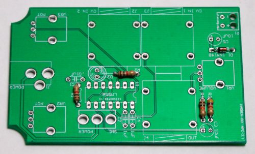
APC HANDHELD – Resistors & Diode
14 Pin Socket
Next is the IC socket. Take care when populating these to not bend any of the legs, and to line up the notch in the end with the same notch that is displayed on the silkscreen. This notch indicates where pin 1 of the IC is. When you have them populated, carefully flip your project over and solder everything in place.
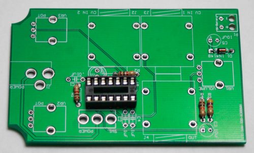
APC HANDHELD SOCKET
Capacitors and LED
Now we can populate the ceramic capacitors. These are non-polarized and can be inserted either direction. Once they are in, carefully flip over your project and solder them in place, clipping the excess leads.
The electrolytic capacitors are polarized, so take care! Ensure that the longer leg (the leg that is further from the stripe indicator on the body) goes through the solder pad with the little ‘+’ symbol next to it. Once it is aligned properly, carefully flip your project over and solder it in place, clipping the excess leads on the bottom.
Next populate the LED. The LED is polarized so make sure that you orient the FLAT part of the LED with the FLAT silkscreen indicator. Flip project over and clip leads.
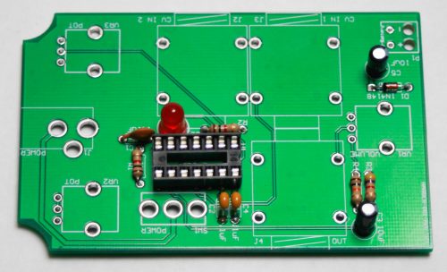
APC HANDHELD Capacitors and LED
REAR MOUNT CAPACITOR
Take one of the 100nF ceramic caps and solder it between pins 2 and 13 as shown below. Trim any extra leads.
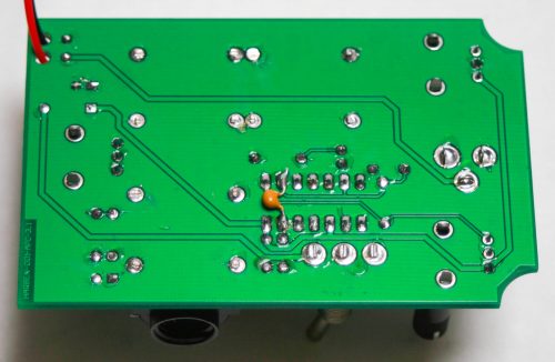
APC HANDHELD 100nF capacitor
DC JACK and 9V BATTERY CLIP
First, populate the DC jack, turn over and solder. Next up, insert the ends of the battery clip through the strain relief holes in the PCB, and then solder each wire into its proper spot. The red goes to the one marked with a ‘+’ and the black wire goes to the ‘-‘.
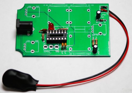
APC HANDHELD DC JACK and 9V Battery Clip
1/4″ Jacks & IC
First place the IC into the socket. Make sure that you line up the notch on the silk screen and the socket with the notch on the IC. Next up are the 1/4 inch jacks. Insert them into the PCB as shown above, then flip over and solder them into place.
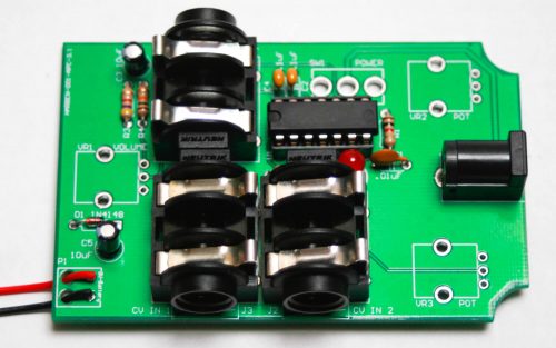
APC HANDHELD 1/4″ Jacks
POTENTIOMETERS & SWITCH
Now insert the three pots into the board as shown below. Turn over to solder and clip. Now place the switch into the PCB, turn over and solder.
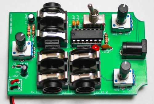
APC HANDHELD – POTENTIOMETERS
Hey! You are done and if you followed these instructions correctly, you will have a working unit! It takes a 9V battery or a 9V center negative power supply. Use a 1/4″ cable and plug it into a mixer, amp or stereo! Enjoy those square waves!