


Important Links
Product Page
Store Page
Assembly Instructions
Bill of Materials
Capacitor and Resistor Lookup Guide
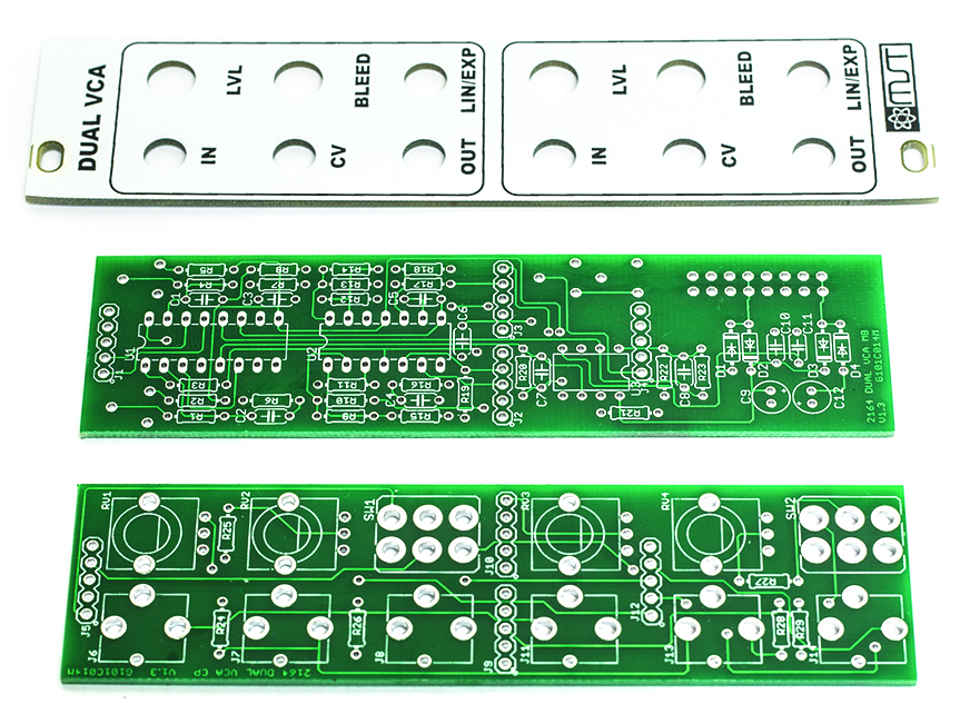
MST DUAL 2164 AC / DC VCA
Thank you for purchasing the MST Dual 2164 AC/DC VCA Eurorack module kit! This is an intermediate to advanced build and not recommended for the beginner since it has a lot of tight fitted parts. If you feel like you can handle it please proceed! If not, get some help from a friend with experience or purchase a fully completed unit.
ATTN: Please follow the BOM and these instructions and don’t populate from the PCB alone. Also sometimes we cannot get the exact pictured components, so please look over your parts and check the codes first. Lets begin with the MAIN Board.
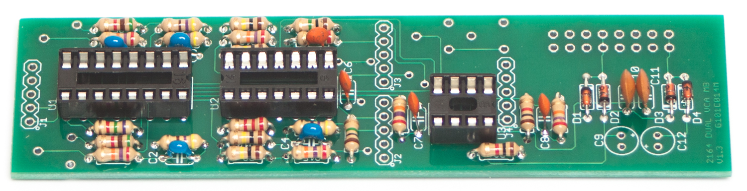
DIODES
Start with the diodes as shown below, then turn over on a firm surface to solder, then clip your leads. Diodes are polarized components so you must match the black stripe on your diodes with the white stripe on the PCB silkscreen.
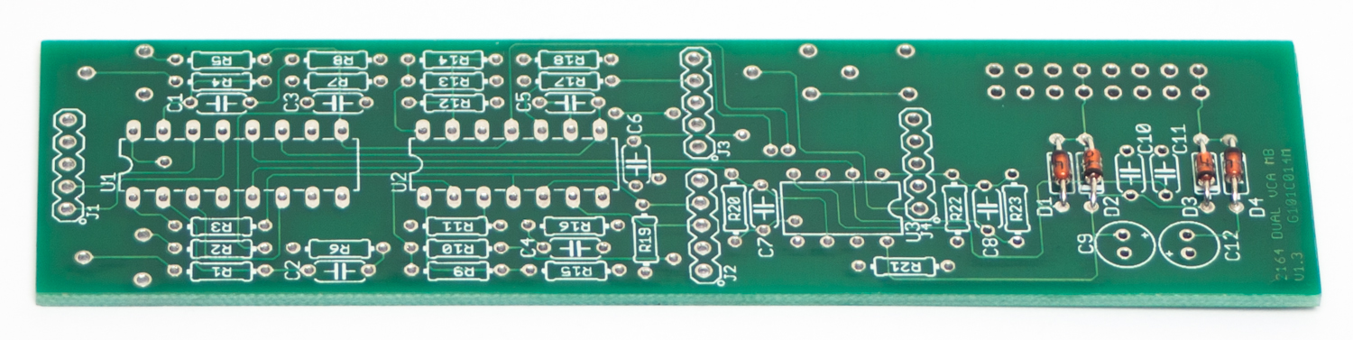
MST DUAL VCA DIODES
RESISTORS
Populate first, then turn over on a firm surface to solder and then clip leads.
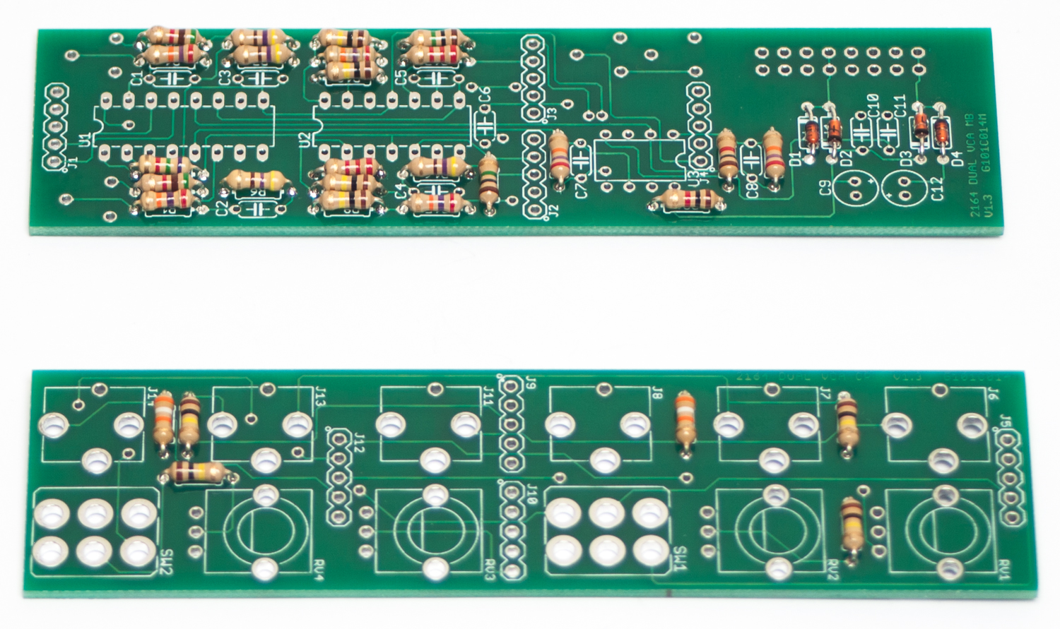
MST DUAL VCA RESISTORS
SOCKETS
Place the IC Sockets by aligning the notch with the notch graphic on the PCB Silk Screen. Turn over on a flat surface and solder into place.
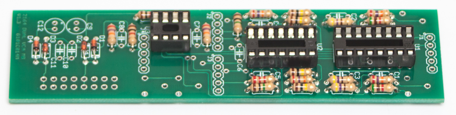
MST DUAL VCA SOCKETS
CAPACITORS
Now populate the capacitors as shown below. These caps are not polarized. Turn over on a flat surface to solder and trim.
MST DUAL VCA CAPACITORS 1
Next, make sure you orient the electrolytic capacitors in correctly. The longer lead needs to be inserted into the hole that has the “+” marking near it. Solder and clip.
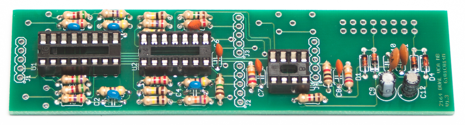
DUAL VCA ELECTROLYTIC CAPACITORS
5-PIN MALE HEADERS
Now populate the 5-pin headers as shown below. Carefully turn over and solder.
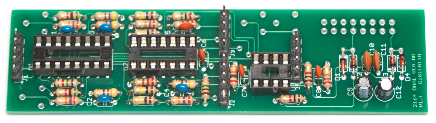
MST DUAL VCA MALE HEADERS
ICs
Next, Carefully insert the ICs into their respective sockets, following the BOM
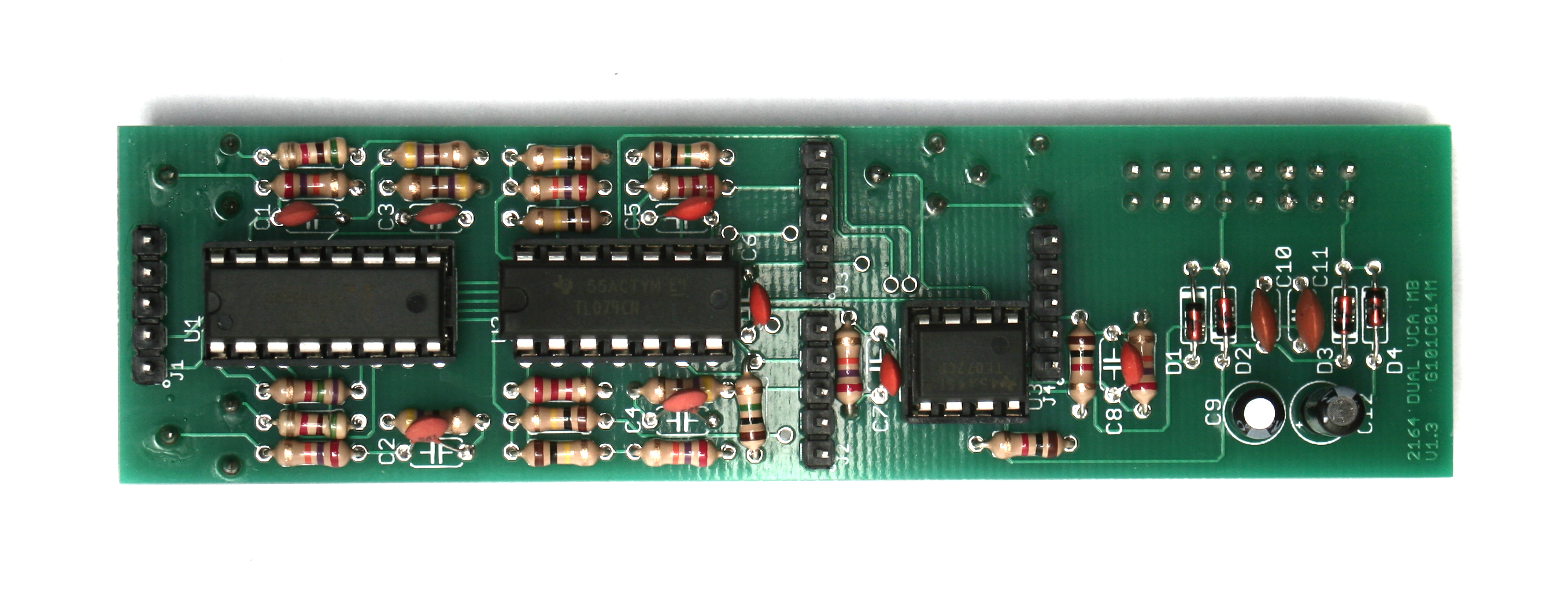
MST Dual VCA ICs
TRIMMER RESISTORS
Populate the trimmer resistors on the rear of the PCB as shown below. Turn over to solder and trim.
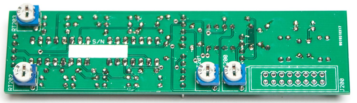
MST DUAL VCA TRIMMER RESISTORS
16-Pin Shrouded Power Connector
Next add the 16-Pin Eurorack Power Connector in place by matching the key notch with the key indicator on the PCB silk screen.
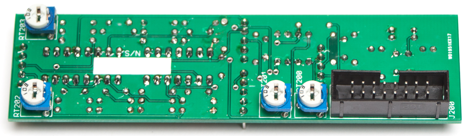
MSDT DUAL VCA EURORACK POWER CONNECTOR
5-PIN FEMALE HEADERS
Now add the 5-Pin female headers to the rear of the control board as shown below. Turn over to solder, then trim.
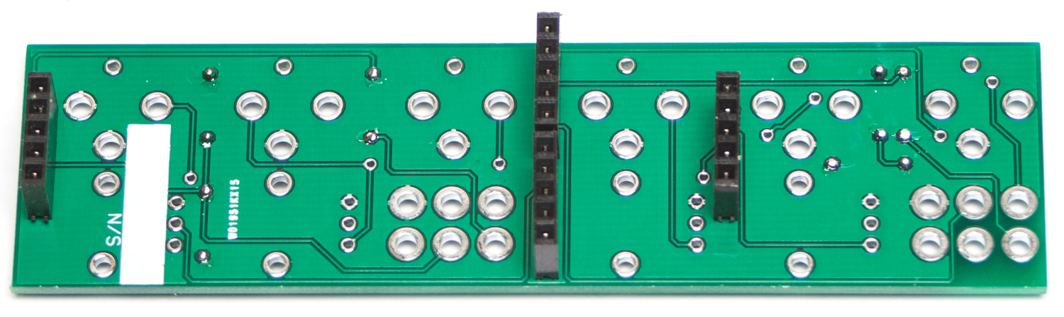
MST DUAL VCA FEMALE HEADERS
JACKS, POTENTIOMETERS & SWITCHES

Don’t forget to cut the nubs on the potentiometers as necessary.
Now PLACE (do not solder yet!) the jacks switches and potentiometers in the circuit board as shown below. Make sure to remove ALL the nuts and washers from your switches before panel placement.
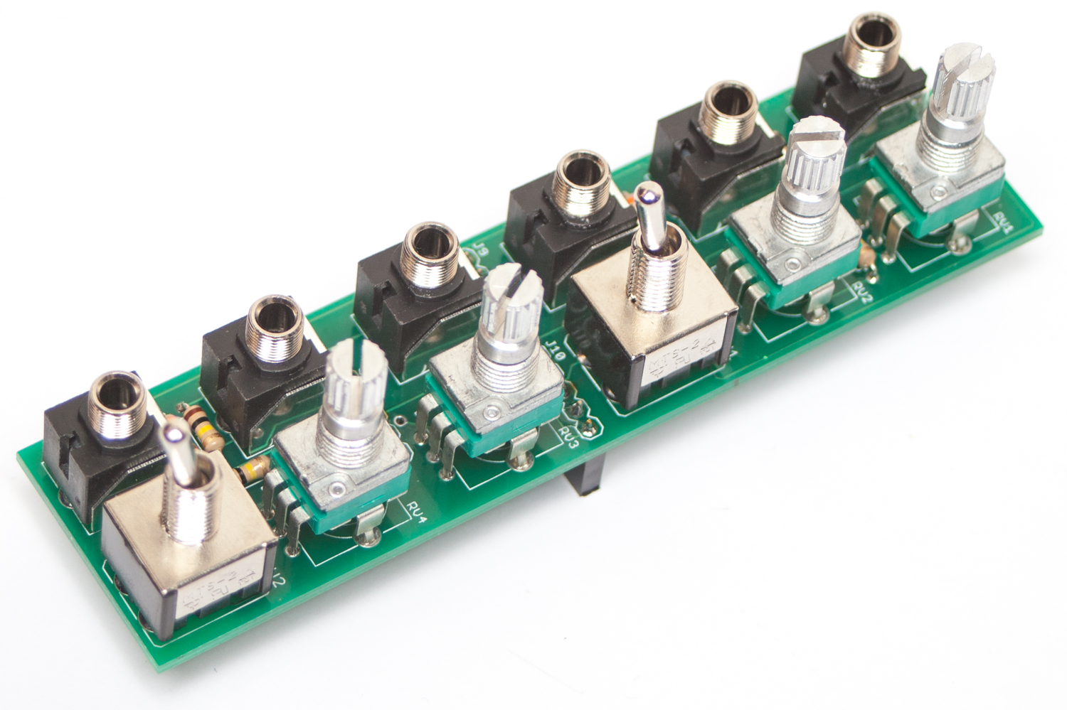
MST DUAL VCA JACK, SWITCH & POT PLACEMENT
Now place the panel over the jacks, pots & switches.
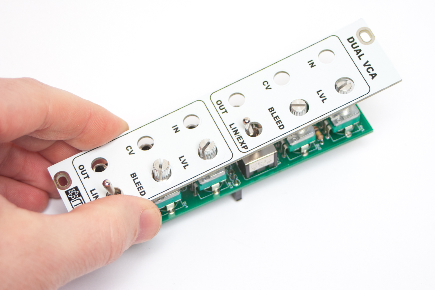
MST DUAL VCA PANEL PLACEMENT
Now fully tighten (not too hard) down the nuts on the jacks, pots and switches.
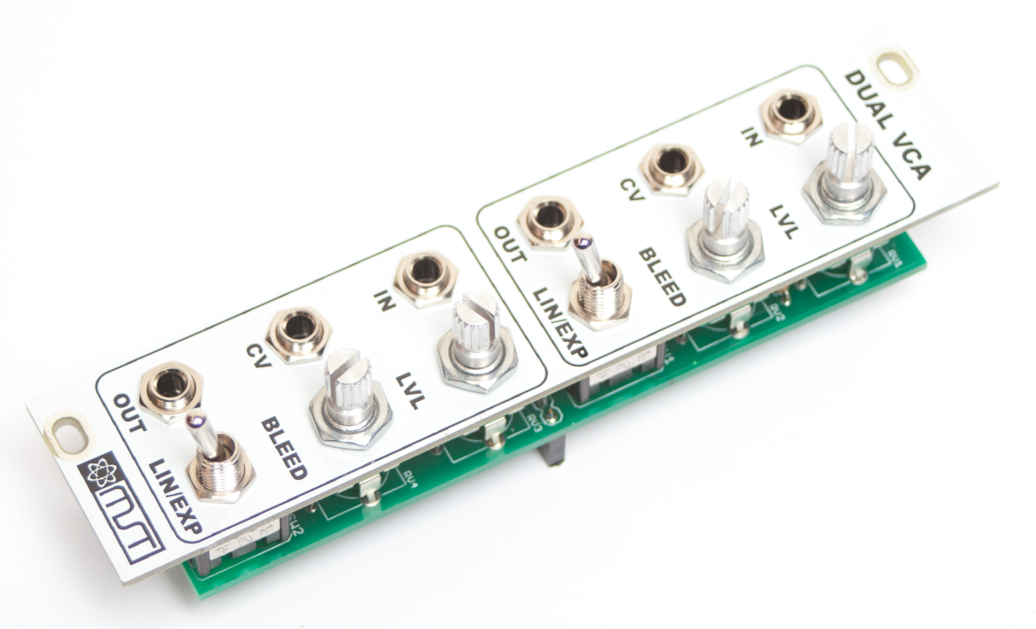
MST DUAL VCA NUTS
Now you will need to move the panel (please be careful and take it slow) in order to make sure that it is level with the control board. This will involve pulling the pot leads and clamps out of the board just a bit. Take your time and get this right!
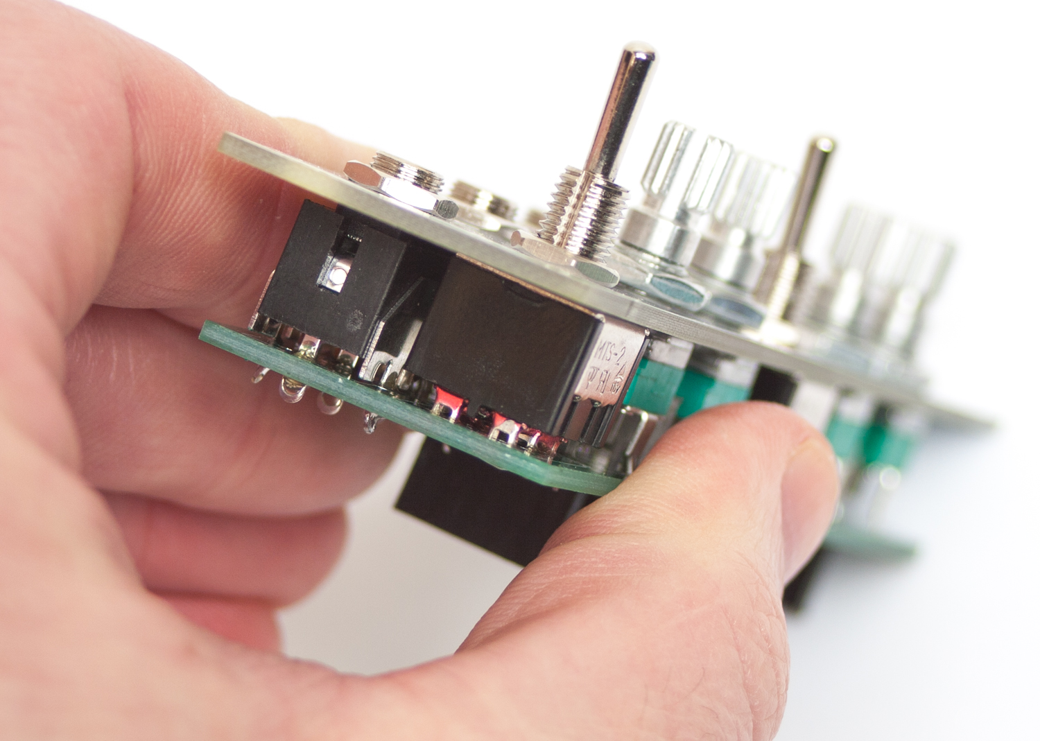
MST DUAL VCA PANEL ADJUSTMENT
Now carefully turn the board over and solder the pots, jacks and switches in place.
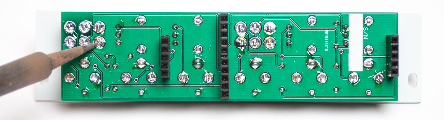
MST DUAL VCA FINAL SOLDERING
Now Carefully! connect the two boards together and NOW you are ready for testing! Plug your power cable into your Eurorack power supply and test away.
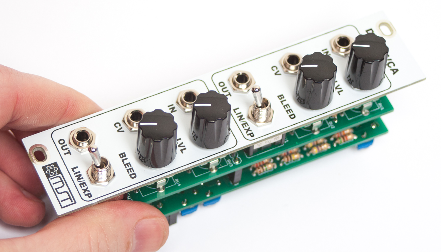
MST VCA FINAL BUILD
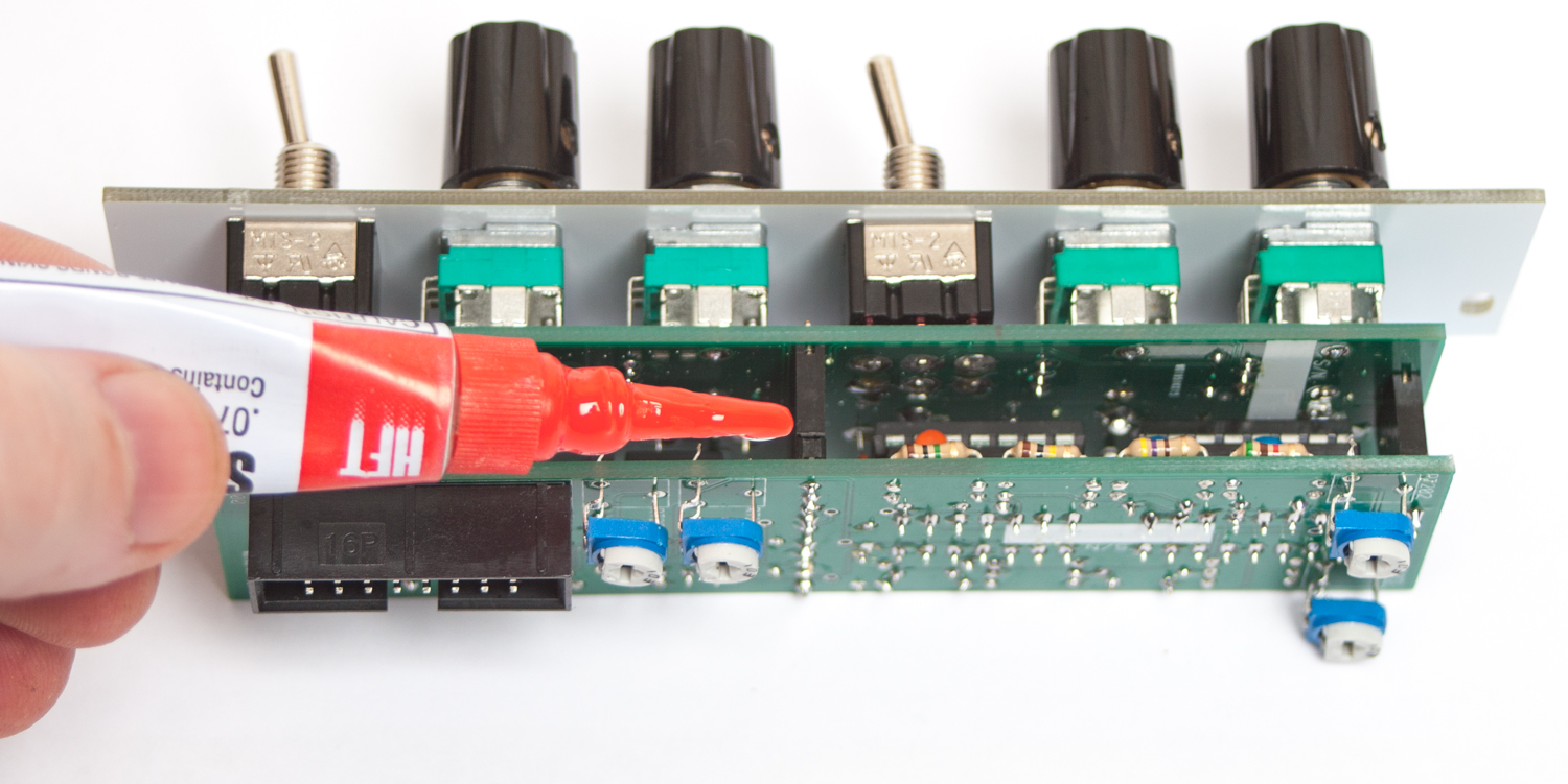
OPTIONAL BOARD TO BOARD GLUING
After you have fully tested your unit and have determined that it is in full working order, you can use some super-glue to bond the board to board headers together. This is an optional step, but will help keep the boards together as you pull the module out of your case. Make sure to not over-glue as you may still need to pull the boards apart in the future. After that, you are ready to use your module with full confidence. Thank you for choosing Synthrotek!
MST DUAL VCA GLUING 1
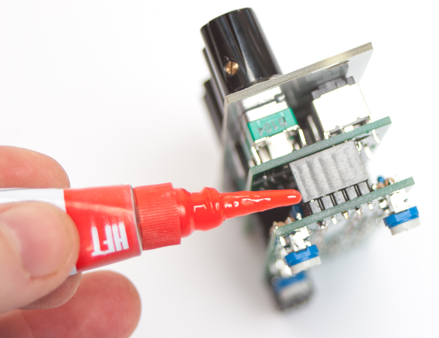
MST DUAL VCA GLUING 2
MST Dual VCA Calibration Instructions
General Patch Setup
The patch we use to calibrate the MST Dual VCA is relatively simple, but calibration requires an oscilloscope, a module that can generate a sine wave, a module that can generate a slow saw wave, a mixer, a mult, and something that can generate a 5v CV signal. The modules that generate your sine wave and slow saw wave can not be the same module, as they need to be a different frequencies.
Plug the sine wave into the mult, and run one output from the mult to the mixer, the other to the VCA. Next, put the output of the VCA to another channel of the mixer. You will need to be able to plug both of these into your oscilloscope, and you can either use a mixer with switches, or just plug and unplug each channel separately.
LEVEL ADJUSTMENT
The first thing we need to set is the overall output level. Make sure you have:
- No CV input
- Turn level fully CW
- Turn Bleed fully CW
With just the sine wave going into the VCA (channel 1), in linear mode, turn trimmer RT201 so that the output level of the VCA matches the output level of the sine wave. This will set the output for both channels.
Channel 1
Now we will set the CV for channel 1.
- Turn Level fully CW
- Turn Bleed fully CCW
- Add 5V signal into CV input of channel one
With the sine wave still in channel 1’s input, adjust trimmer RT202 so that the output level of the VCA matches the output level of the incoming sine wave.
Channel 2
Now we will set the CV for channel 2. Bring each plug from channel 1 to the corresponding jack in channel 2.
- Turn Level Fully CW
- Turn Bleed Fully CCW
- Use the same CV input from the previous step, plugged into channel 2’s CV in.
Now adjust trimmer RT203 so that the output level of the VCA matches the output level of the incoming sine wave.
Exponential Calibration: (works for both channels)
- Keep sine wave input in channel 2 input
- Plug your sawtooth wave into channel 2 CV in.
- Turn Level Fully CW
- Turn Bleed Fully CCW
- Put the switch in Linear mode. (down)
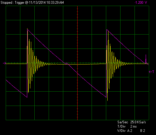
With it set up like the above bullet points, look at the oscilloscope’s screen. You should see something similar to the picture below. We call that the ‘Linear Christmas tree’. Yours should look very similar.
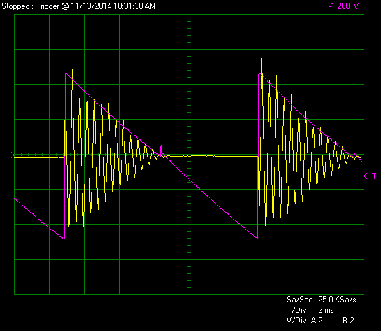
Flip the switch on the VCA into exponential mode, and then adjust RT200 until you see a new ‘Christmas tree’ that looks like the one below. The edge of it should have a nice exponential curve to it. Make the level of the exponential either match, or about .5 volts higher to get a nice ‘pop’ sound from your VCA.
Make sure to insert the ICs into their sockets before connecting the PCBs and powering on the module :-0
If you are sourcing your own parts, be aware that the Mouser ID number in the BoM for the electrolytic capacitor will give you a cap that is too big in diameter to work as shown in this build guide. Additionally I think it is too tall as well, I don’t see any way these are not going to interfere with the header clearance.
I’m going to experiment with bending these parallel to the board, it looks like there is room but I also have some equivalent caps in a smaller package being shipped just in case. From what I can tell, these caps are used in most if not all of the MST line so I wanted to give a heads up to fellow builders.
@Jakelin
i just built mine and have the too-tall cap issue too. is there a danger of shorting anything if the cap touches off a solder joint on the other board or will i just need to get shorter ones or bend them a bit?
Hello,
You can safely bend the caps without issue, but if they touch solder joints on the top, it will short out and cause some problems. I would recommend getting shorter ones, if possible, or bending them.
best,
-Patrick at Synthrotek
@Patrick Kelly
thanks patrick!
I built my kit using your parts, and both VCAs work fine on the Linear setting, but I am getting no output at all from the Exponential setting. I’ve looked over all the solder points, insertion of ICs, orientation of diodes, etc., and everything looks good. Do you have any suggestions for places to look for problems? Is there something I’m supposed to do with the trim pots?
Thanks for any suggestions!
Hey Robert,
If you haven’t calibrated the VCA, the exponential output is going to be too low to be heard. If you head over to the Product Page, and scroll to the bottom, there are calibration instructions there. Alternatively, RT200 is the trim pot that controls the exponential function, you can just adjust that trim pot CCW until you are satisfied with the sound.
Best Regards,
-Patrick at Synthrotek
@Patrick Kelly
Thank you, Patrick! RT200 did the trick!
Robert
You’re welcome! Glad it was as simple as turning a trimmer.
Best,
-Patrick
@Jakelin
Just mount the electrolytics on the back of the board with the trimmers and 16 pin header. No need to reorder parts.
For the 10 uf electrolytic Capacitor will 50VDC work fine? I don’t see any reason it would not. I am looking at Mouser Part number 667-ECE-A1HKA100I .
Hi Sean, that will work just fine. You can go over on voltage.
I bought the mst dual linear vca already built on reverb but when it came the cable was unplugged , and i cant find any marking for neg 12. I assume it would b on bottom of the 16 pin but not sure and dont want to cause any harm. Can anyone please tell me how to tell or wich end neg 12 will b on? Please and thankyou.
Red Stripe Down on this one toward the bottom of the PCB