


Important Links
Product Page
Store Page
Quick Start Guide
Manual
Assembly Instructions
Bill of Materials
Capacitor and Resistor Lookup Guide
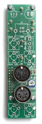
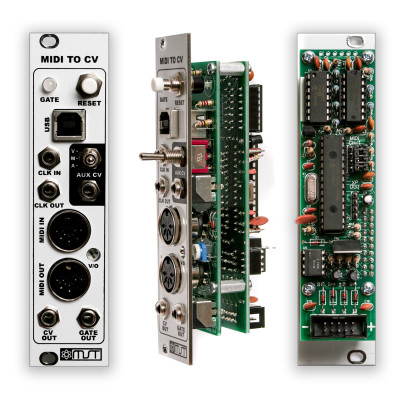
MST MIDI to CV Converter
Thank you for purchasing the MST MIDI to CV Eurorack module kit! This is an intermediate build. If you feel like you can handle it, please proceed! If not, get some help from a friend with experience or purchase a fully completed unit.
ATTN: Please follow the BOM and these instructions and don’t populate from the PCB or these instruction pictures alone. Also sometimes we cannot get the exact pictured components, so please look over your parts and check the codes first.
Lets begin!
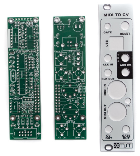
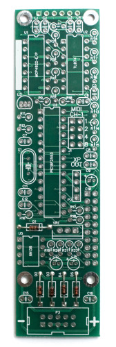
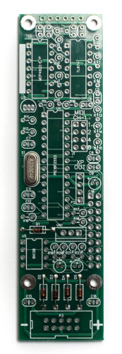
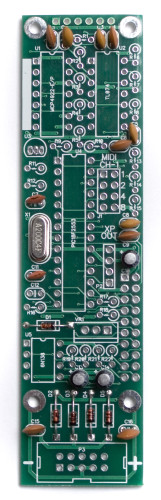
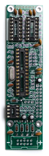
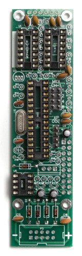
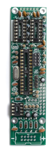
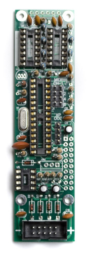
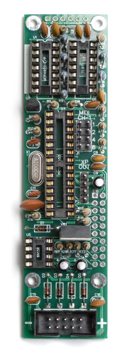
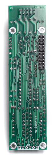
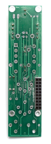
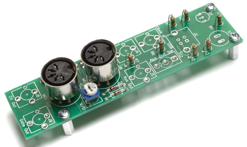
Logic Board
We are going to start with the logic board for this build, it is the PCB with all the ICs on it.
Diodes
MST Midi to CV Diodes
Diodes are polarized components, so when inserting the into the PCB, make sure to line up the stripe (cathode) on the diode with the matching stripe on the silkscreen of the PCB. Once you have them all populated, flip your board over onto a hard, flat surface. Then solder and clip your leads.
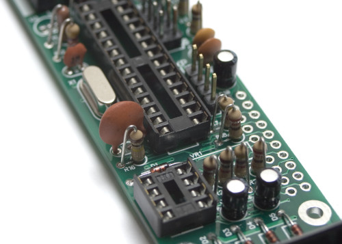
20MHz Crystal
MST Midi to CV Crystal
Now we will solder the crystal into place. Crystals are not polarized, so you can insert it either way without worry. Like with the diodes, flip the board over, solder the crystal in place, and clip the excess leads.
Capacitors
MST Midi to CV Capacitors
Next up are the capacitors. Since the electrolytics included in the kit for this are nice and small, we can go ahead and do all the capacitors together. If you purchased your own components, you may need to do the ceramics first, then the electrolytics. NOTICE: Do NOT populate C12 yet. This capacitor is a bit larger than a lot of other things, and can get in the way if soldered in now.
When you are populating the electrolytic capacitors, make sure that you pay attention to where the side with the stripe (cathode) is going. These guys are polarized (like diodes), and need to be oriented properly, or you could risk damaging your module, or yourself. Make sure to align the stripe so that it points AWAY from the little ‘+’ marking on the silkscreen.
Afterwards, flip the project over, solder and clip any excess leads.
IC Sockets
MST Midi to CV IC Sockets
Now we can move on to the IC sockets. When inserting them into the board, make sure to line up the half moon notch in the one end with the same half moon notch that is depicted on the silkscreen of the PCB. Once these are in the board, carefully flip it over. You can use a piece of cardboard, or another PCB, or hard plastic to help you flip the board with IC sockets over. Then you can solder them in place. An easy way to make sure they get soldered in nice and flat is to start by only soldering one or two of the pins, and then checking how level it is. You can then re-heat the solder joint while GENTLY applying pressure to make it sit flat.
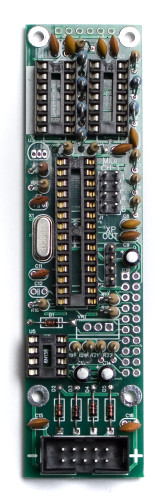
Headers
MST Midi to CV Headers
Next, insert both the 4 pin and 8 pin headers into the PCB. Like with the IC sockets, we can use a piece of cardboard to help us flip the project over. Then solder them in place.
If you have the newer revision with a DIP switch and I2C header, place those in the board instead.
Resistors
MST Midi to CV Resistors
The resistors in this project are standing on end, so when bending them to insert, care must be taken not to make the top bend too close to the body of the resistor, or the tension may end up damaging the resistor. Insert all the resistors into their proper places, taking care with the 1% resistors. Then carefully flip the project over, solder and clip any excess leads.
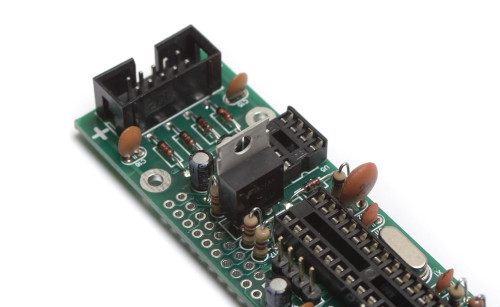
10 Pin Power Header
MST Midi to CV Power Header
When inserting the 10 pin shrouded header into the board, take care to line up the notch in the shrouding with the notch designation on the silkscreen. If this part is put in backwards, your module will not work, and has a very good chance of being damaged. Once you are sure of the orientation, flip the project over and solder it in.
C12
Now its time to solder in C12. Its a 220nF ceramic capacitor. The body on this capacitor (if it’s the one we sent with the kit) is quite large, which is why it is soldered in separately.
MST Midi to CV C12 closeup
When placing C12 into the Board, the leads are a little bit too wide for the silkscreen, so the legs need to be bent a little, and it won’t sit flat. Try to make it look as much like the picture above as possible so that it doesn’t stick over the side edge and interfere with any other modules. Once you are happy with the placement, flip the project over, solder and clip excess leads.
Voltage Regulators
MST Midi to CV Voltage Regulators
Next up are the two voltage regulators. When populating these, take care to note how they are oriented on the board. The TL431 (smaller one) has one flat side that needs to match up with the flat part of the silkscreen on the board, as shown above. For the 78L05 regulator, the metal heat sink needs to be on the bottom side of the board (closer to the power connector). Please carefully look at the pictures to make sure your orientation is right.
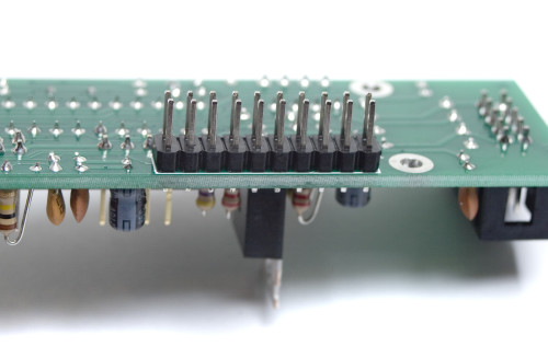
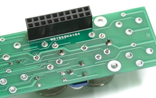
20 Pin Header
MST Midi to CV 20 Pin Header
Next up is the 20 pin header that goes on the bottom of the board. This is the connector that goes between the logic board and the control board, so it needs to be soldered in nice and flat. The same trick that was used with the IC sockets will work here too. Solder one or two pins, and then re-heat the solder while GENTLY applying pressure to make it sit nice and flat. Be careful not to push on the same pin you are heating up, because the heat will travel VERY quickly and may burn you.
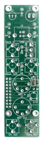
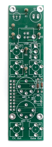
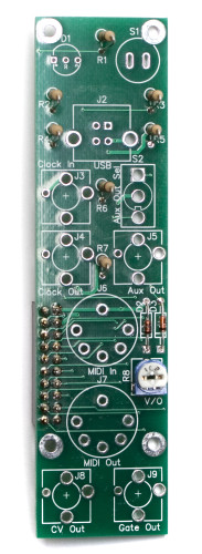
Control Panel
We are now ready to start with the control panel for this project.
Diodes
ATTENTION: The zener diode for the MST Midi to CV Converter MUST be the Fairchild 4.7v Zener diode. The mouser part number is 512‐1N5230B. Other 4.7v zener diodes will NOT work.
MST Midi to CV Diodes
Insert the diodes into the control panel, taking care to align the stripes, just like on the logic board. Make sure that the zener diode goes into the proper spot, as the module can’t work properly without it.
Resistors
MST Midi to CV Control Panel Resistors
Now we can move on to the seven resistors on the control panel. Just like the ones on the logic board, these are vertical mount. Insert them into their proper places as per the BOM, and then flip the project over, solder, and clip any excess leads.
20 Pin Socket
MST Midi to CV Control Board socket
Next up is the 20 pin socket that goes on the back side of the board. This is the counterpart to the 20 pin header we did earlier, so it needs to be flush against the board as well so they line up properly.
Trimmer Potentiometer
MST Midi to CV Control Panel Trimmer Potentiometer
Next, insert the trimmer potentiometer into it’s proper place, and then flip the project over and solder it in place.
Midi Jacks
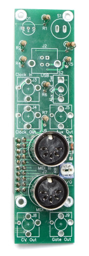
MST Midi to CV Control Panel Midi Jacks
Next up are the midi jacks. The pins on these jacks are loose by design, so the easiest way I’ve found to solder them in place is to just solder one leg until the final step. This way you can make sure that you are getting them nice and flat in relation to the front panel. When inserting these, align the half moon of pins with their holes on the board. Flip the project over, and solder one pin.
Board to Board Standoffs
MST Midi to CV Standoffs
Next, attach the standoffs to the control board by inserting the 2.5mm screws through the holes, and then tightening the standoff to it by spinning it. Once you’ve done all four, you can go back with a screwdriver and SLIGHTLY tighten them. Do not over-tighten the standoffs.
Front Panel Component Placement
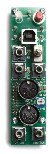
Next up we are going to be placing all of the front panel components (like jacks and switches). Insert all components so they match the picture above. The jacks will only easily go in one way, but the led can go either way. Make sure to line up the flat side of the led (left in the picture) with the flat spot on the silkscreen below it. The USB jack can only go in one way, but it can be a little tricky to get all of the pins into their holes at once.
DO NOT SOLDER ANYTHING YET!
Put the front panel on first to line everything up.
Front Panel Placement
MST Midi to CV Front Panel Placement
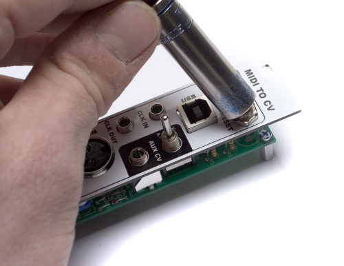
Place the front panel over the jacks, switch and led, being careful not to knock anything out of its place. Next go through and hand-tighten all the nuts. Once all the nuts are hand-tightened and everything looks good, you can go around with a socket (10mm for the button, 8mm for switch, and jacks) and GENTLY tighten the nuts.
Now you can flip the project over and solder all the parts into place. When you flip the board over, make sure the LED goes into the hole on the front panel and sticks out so its visible.
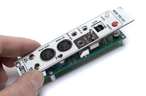
Final Assembly
MST Midi to CV Final Assembly
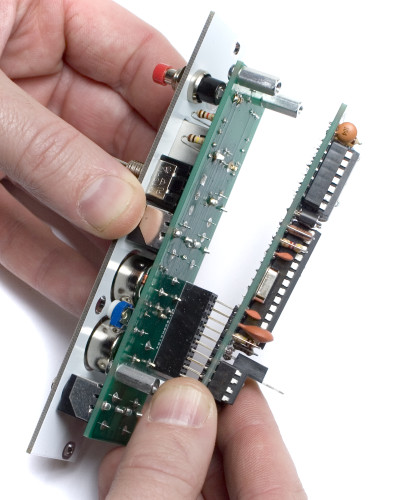
At this point, we are ready to mate the two boards together. Hold them like shown above, so the 20 pin header and socket line up, and gently push them together until the standoffs are touching the logic board.
Fasten Standoffs to Logic Board
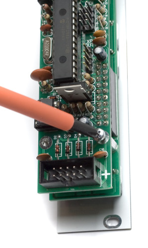
MST Midi to CV Final Assembly
Next, insert your remaining 2.5mm screws into the holes in the logic board and tighten them down snugly (but NOT too hard!) into the standoffs.
Congratulations! You’ve just finished building!
Please see the MIDI to CV Manual for calibration instructions.