


Important Links
Product Page
Store Page
Assembly Instructions
Bill of Materials
Capacitor and Resistor Lookup Guide
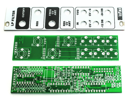
MST Low Pass Filter PCBs & Panel
Thank you for purchasing the MST Low Pass Filter Eurorack module kit! This is an intermediate to advanced build and not recommended for the beginner since it has a lot of tight fitted parts, and stand up resistors. If you feel like you can handle it please proceed! If not, get some help from a friend with experience or purchase a fully completed unit.
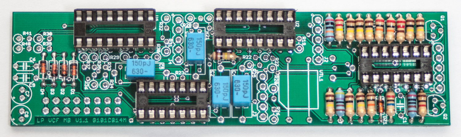
ATTN: Please follow the BOM and these instructions and don’t populate from the PCB alone. Also sometimes we cannot get the exact pictured components, so please look over your parts and check the codes first. Lets begin with the MAIN Board.
DIODES
Start with the diodes as shown below, then turn over on a firm surface to solder, then clip your leads. Diodes are polarized components so you must match the black stripe on your diodes with the white stripe on the PCB silkscreen.
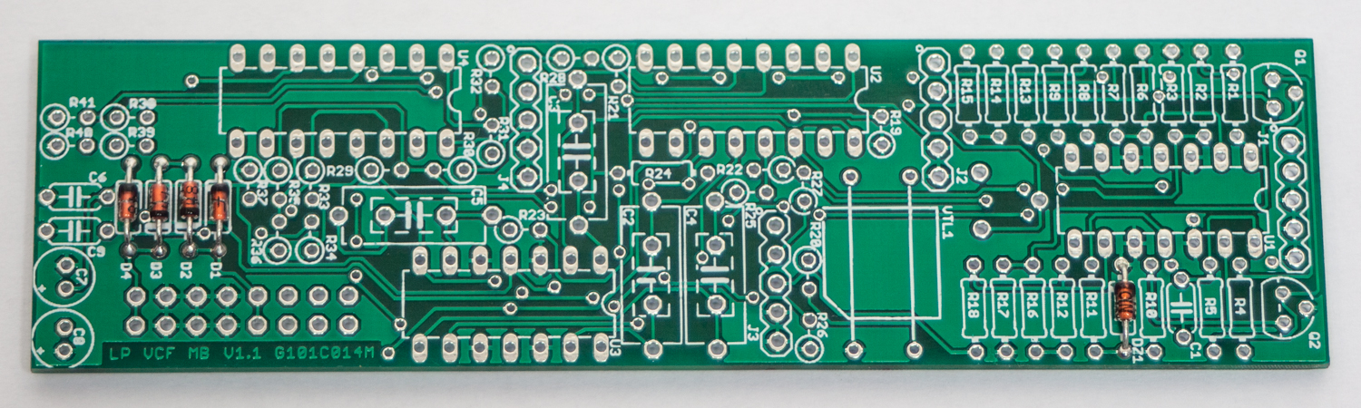
MST Low Pass Filter Diodes
RESISTORS
The MST Low Pass Filter has quite a few resistors that are flat some that need to be installed standing up. Let’s first install the flat mounted resistors. Populate first, then turn over on a firm surface to solder and then clip leads.
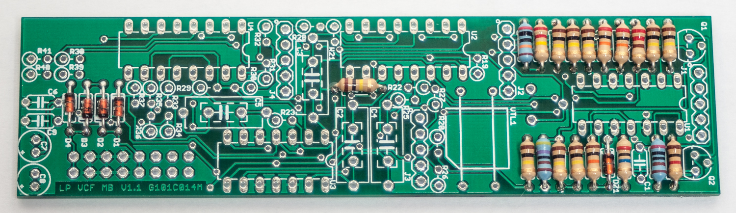
MST Low Pass Filter Resistors
SOCKETS
Place the IC Sockets by aligning the notch with the notch graphic on the PCB Silk Screen. Turn over on a flat surface and solder into place.
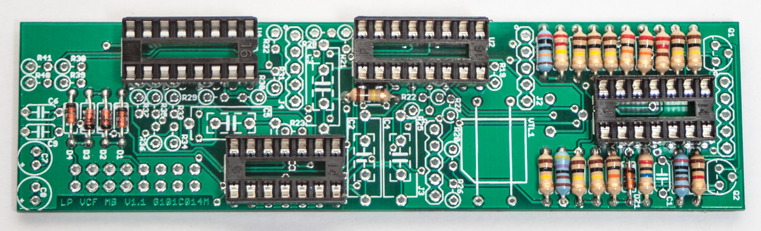
MST Low Pass Filter IC Sockets
FILM CAPACITORS
Now populate the film capacitors as shown below. These caps are not polarized. Turn over on a flat surface to solder and trim.
MST LPF Film Capacitors
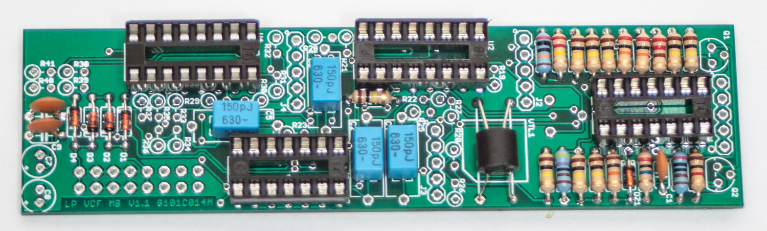
CERAMIC CAPACITORS & VACTROL
Add the two ceramic capacitors and the vactrol as shown below.
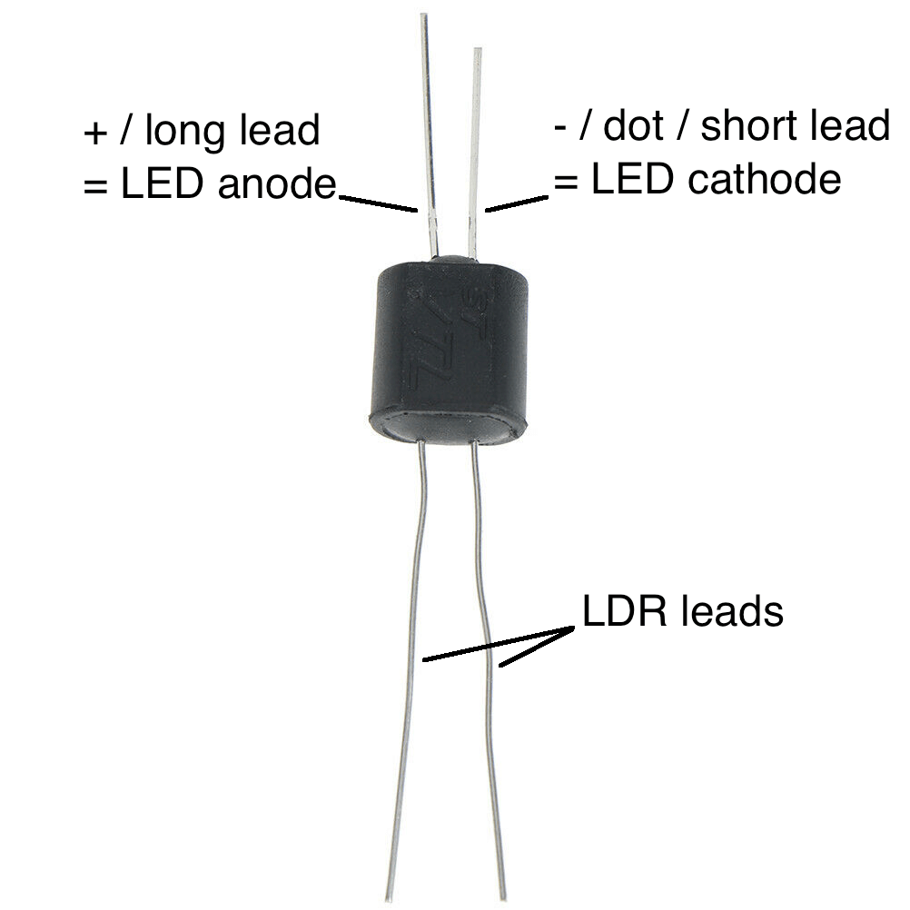
NSL-7053 Vactrol
The Vactrol (optocoupler) is a polarized component you must align the small white with the diagonal mark on the square on the PCB silkscreen.
MST LPF Ceramic Capacitors & NSL-7053 Vactrol
VTL5C3 Vactrol
There is a small “+” sign on the side of the vactrol that needs to be oriented on the OPPOSITE side of the diagonal corner on the PCB. Look for the red + in the picture below for the proper alignment. You want to line it up so that the “+” sign is facing AWAY FROM the film caps.
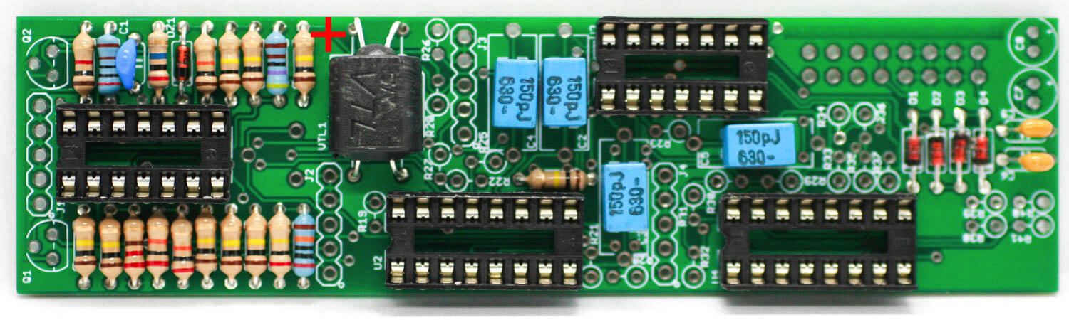
Align the + on the VTL5C3 with the red plus in the picture
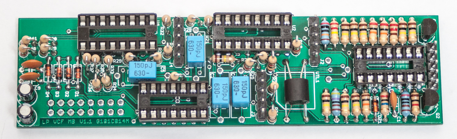
STAND-UP RESISTORS, TRANSISTORS, & ELECTROLYTIC CAPACITORS
Now populate the remaining resistors which are easiest inserted if you bend one lead over first and align the body of the resistor with the circle marking on the pcb silkscreen. Carefully turn over to solder and trim. Next, make sure you orient the electrolytic capacitors in correctly. The longer lead needs to be inserted into the hole that has the “+” marking near it. Solder and clip. Next add the transistors by matching the flat side of the transistors with the flat side on the silk screen. Turn over, solder and clip all leads.
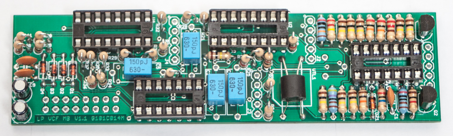
MST LPF Stand-up Resistors
5-PIN MALE HEADERS
Now populate the 5-pin headers as shown below. Carefully turn over and solder.
MST LPF 5-Pin Male Headers
TRIMMER RESISTOR & 16-Pin Shrouded Power Connector
Next add the 16-Pin Eurorack Power Connector in place by matching the key notch with the key indicator on the PCB silk screen. Next add the trimmer resistor as shown below and solder in place.
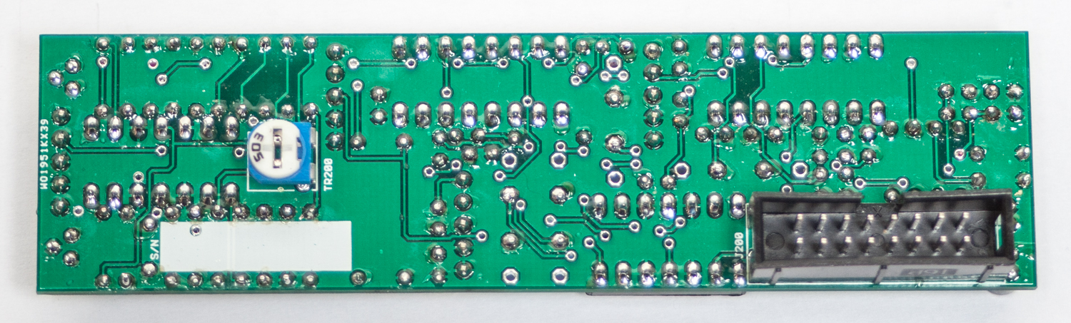
MST LPF TRIMMER & POWER CONNECTOR
INTEGRATED CIRCUITS
Place the ICs in place by aligning the notch with the notch graphic on the PCB Silk Screen and notch on the sockets.
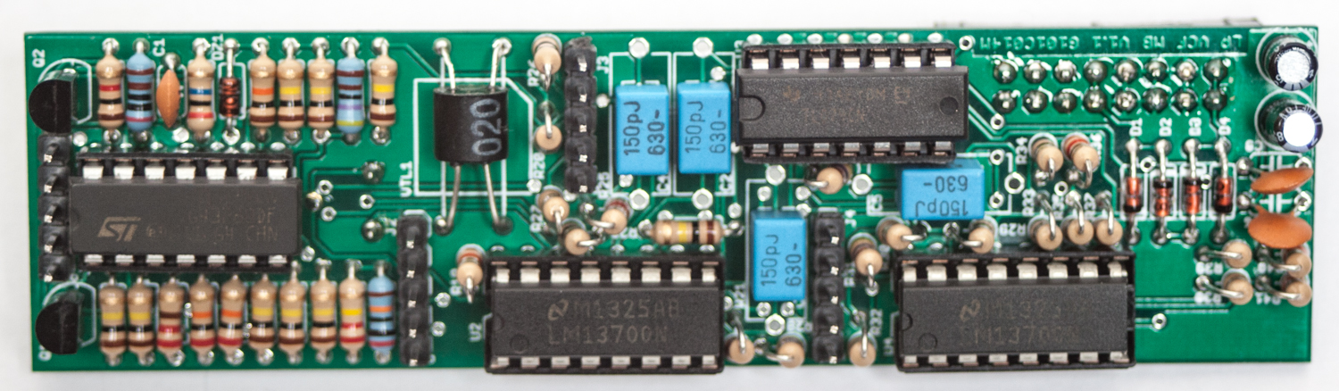
MST LPF IC PLACEMENT
Congrats! You are now done with the MST LPF Main Board. We are now going to move onto the Control Board.
CONTROL BOARD
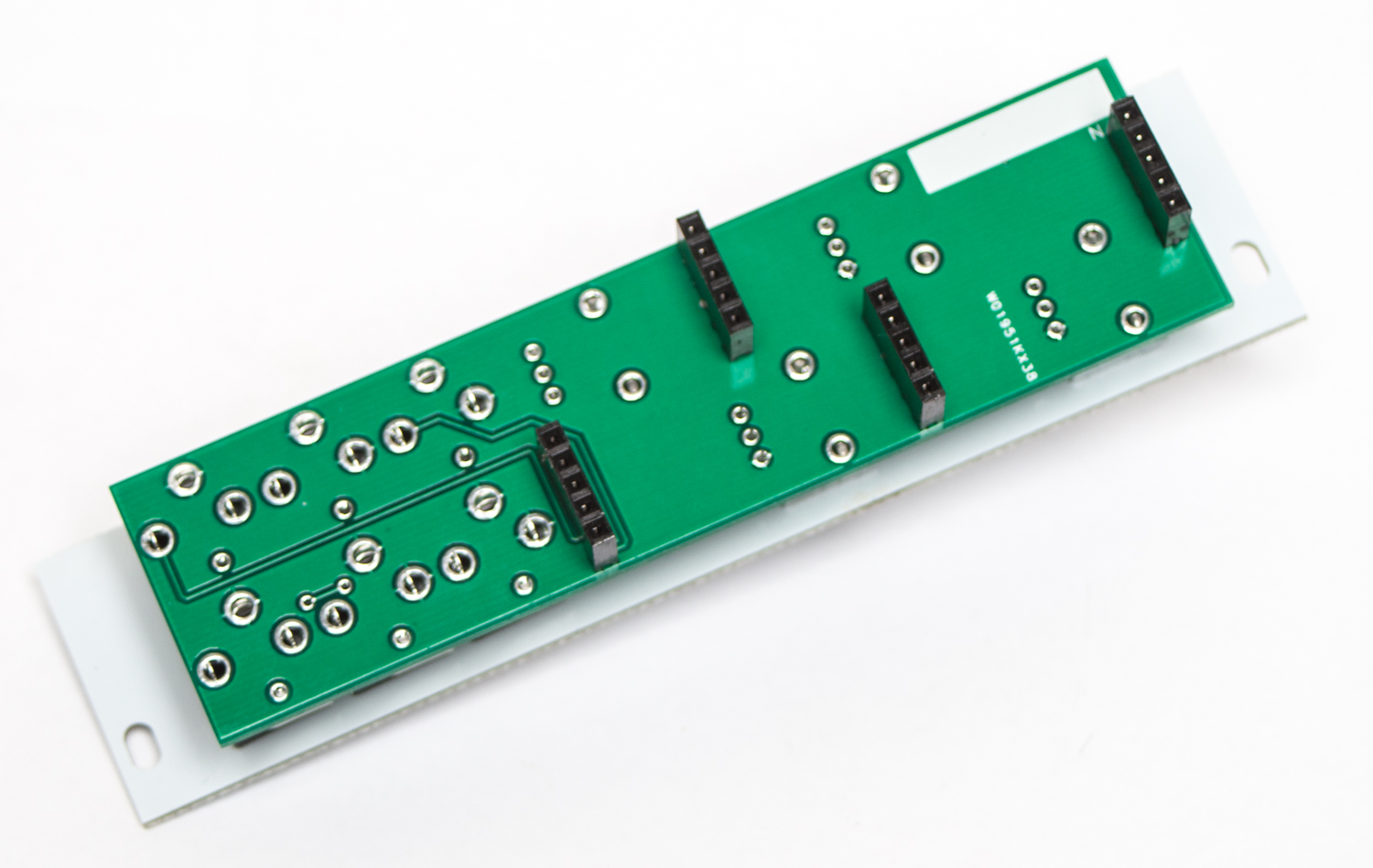
5-PIN FEMALE HEADERS
Now add the 5-Pin female headers to the rear of the control board as shown below. Turn over to solder, then trim.
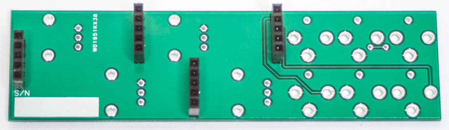
MST LPF Female Headers
15MM STANDOFFS
Next up are the 15mm hex standoffs. We need to put these on before putting the panel on. Start by inserting the screw through the PCB from the front (the side opposite the headers) and screw the stand offs onto them from the back.
JACKS & POTENTIOMETERS

Don’t forget to cut the nubs on the potentiometers as necessary.
Now PLACE (do not solder yet!) the jacks and the potentiometers in the circuit board as shown below.
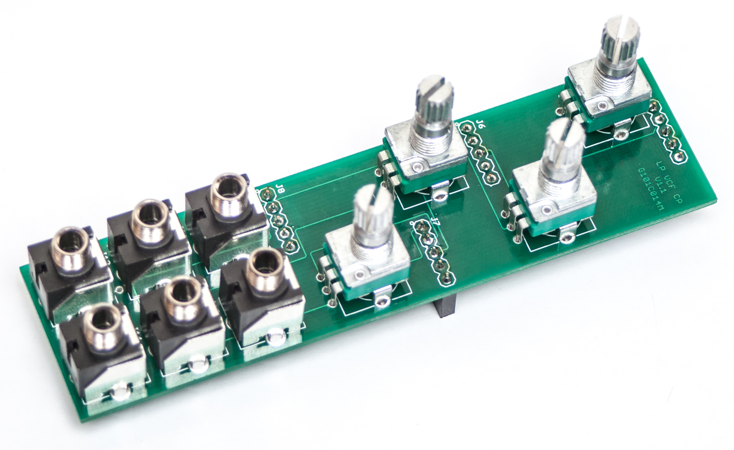
MST LPF Jacks & Pots
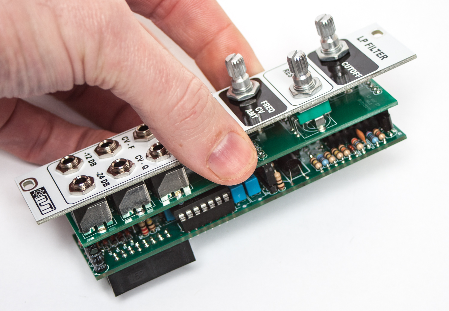
Now place the panel over the jacks and pots.
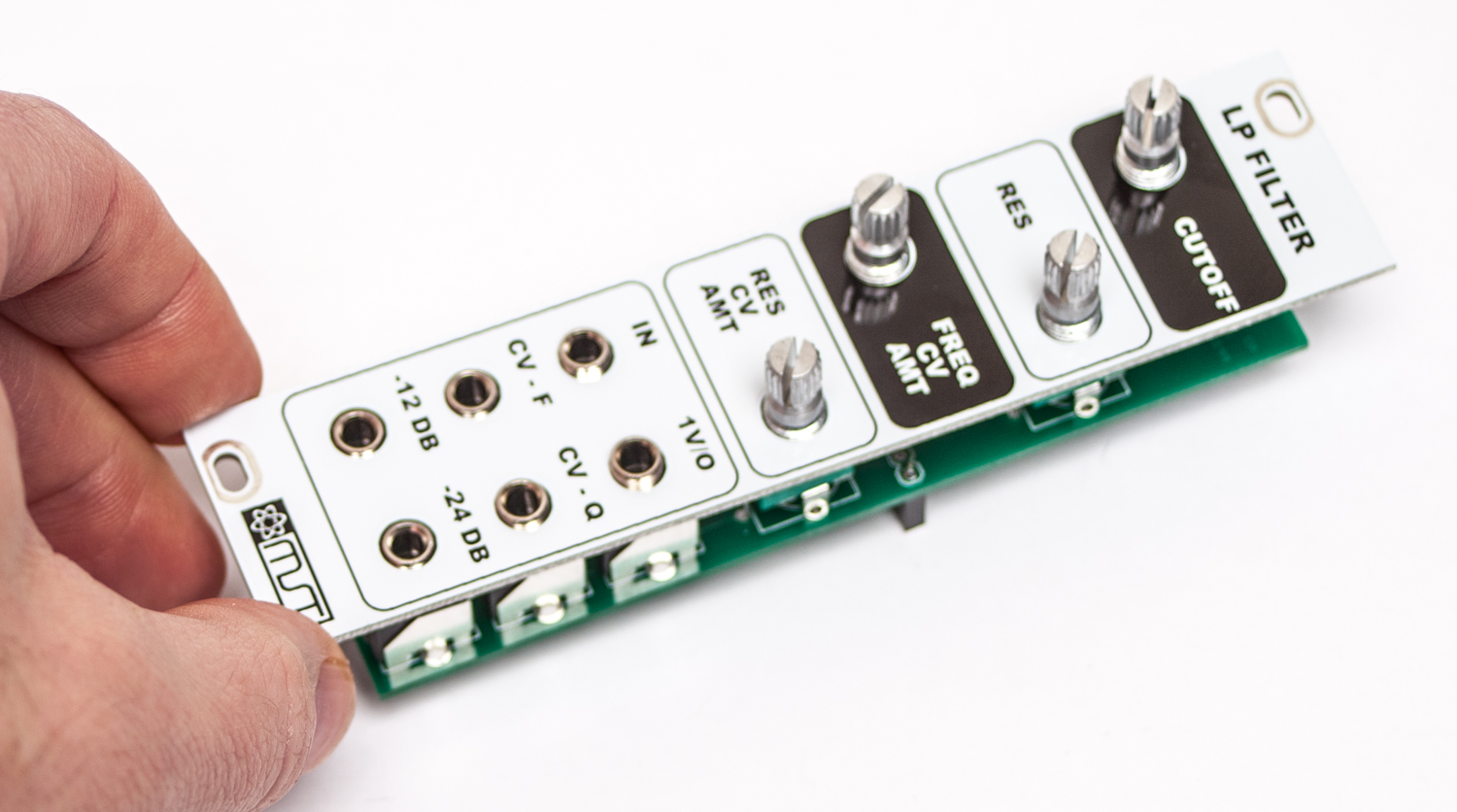
MST LPF Panel Placement
Now fully tighten (not too hard) down the nuts for both the jacks and pots.
MST LPF jack and pot nuts
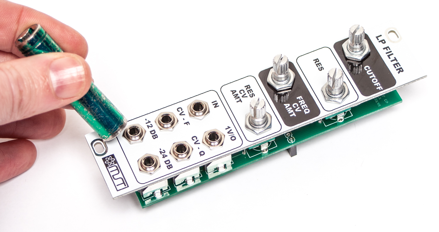
Now you will need to move the panel (please be careful and take it slow) in order to make sure that it is level with the control board. This will involve pulling the pot leads and clamps out of the board just a bit. Take your time and get this right!
MST LPF Align Panel
Now carefully turn the board over and solder the pots and jacks in place.
MST LPF Jack & Pot Soldering
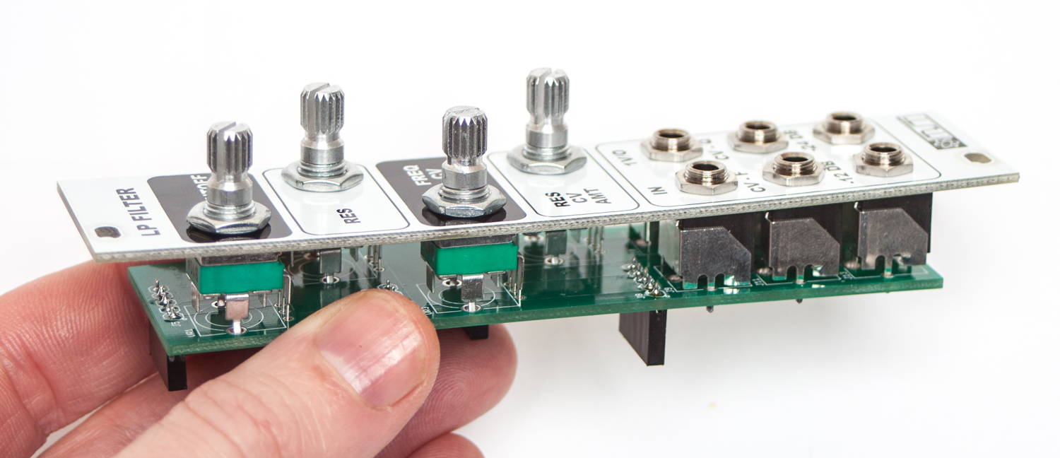
MST LPF Main Board & Control Board Connection
Next, carefully connect the two boards together via the headers. The standoffs should line up with the holes in the logic board. Take your 2.5mm screws, and screw them through the holes in the PCB, into the standoffs. This will secure your module from coming apart.
Plug your eurorack cable in, and you are ready for testing and tuning!
For the tuning instructions, please see the Product Page
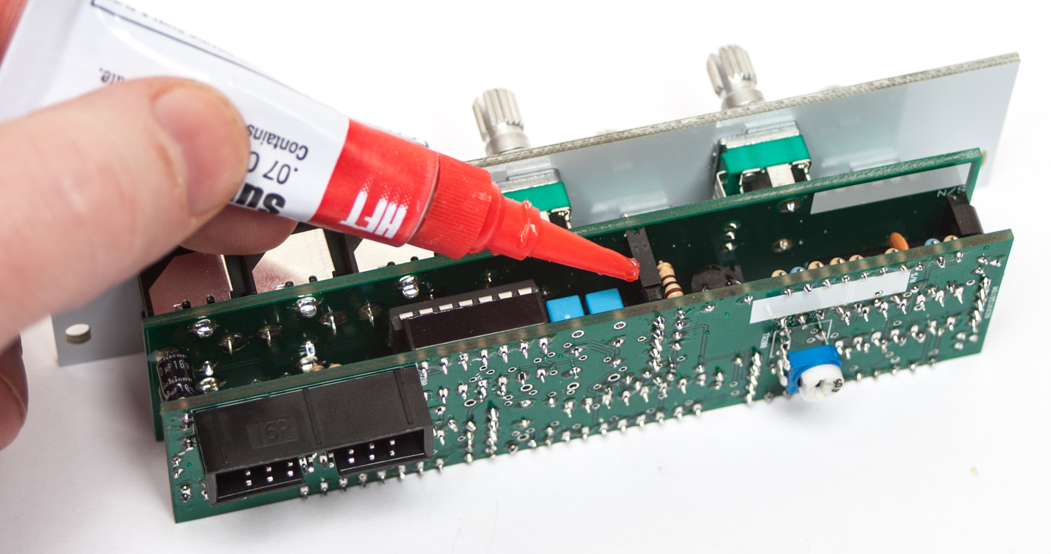
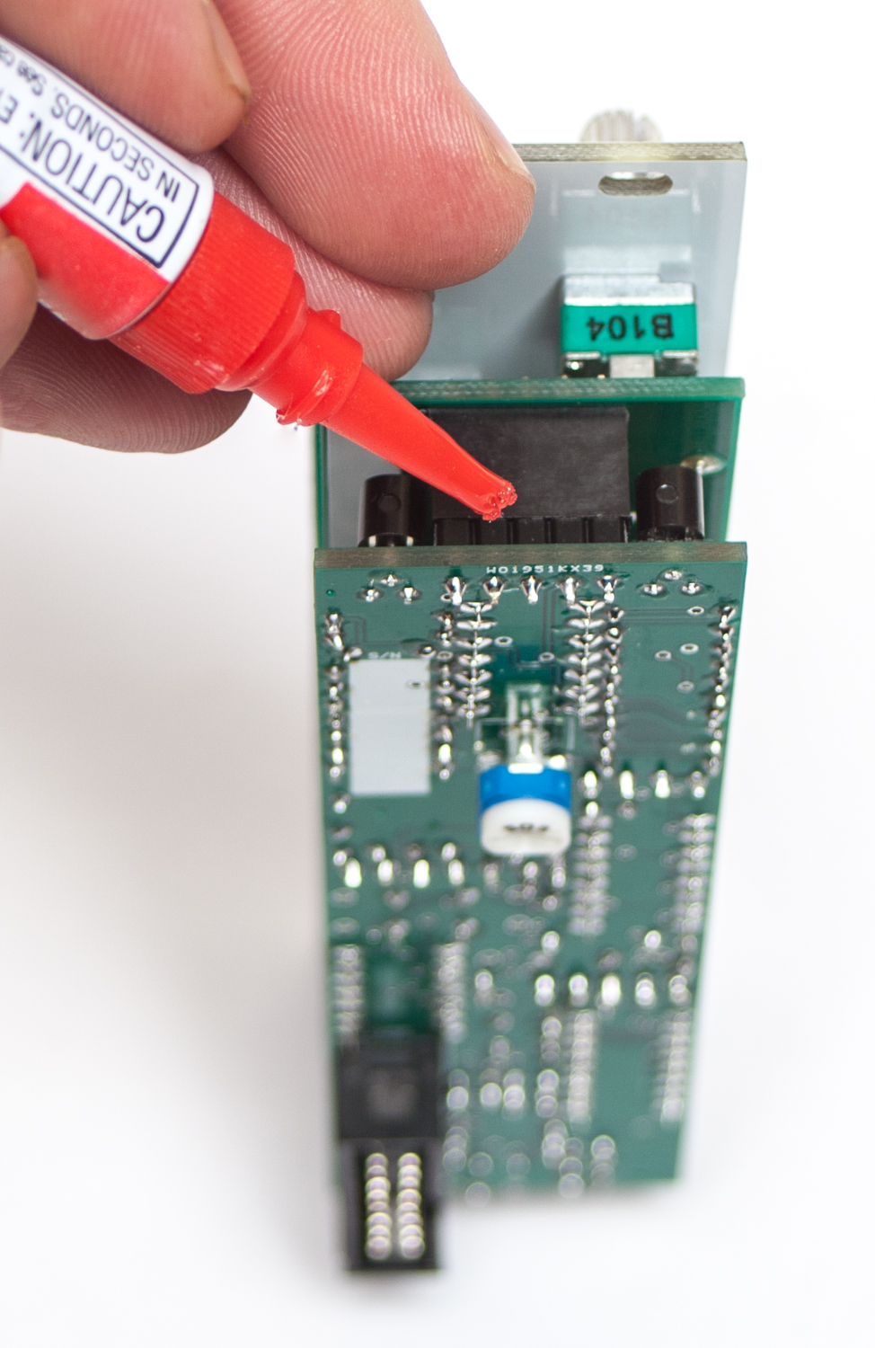
OPTIONAL BOARD TO BOARD GLUING
If you purchased a MST VC LPF more than a few months ago, you may not have the version with stand offs. The headers may or may not be enough to hold it together, depending on if you travel with your eurorack setup. If you move modules around a lot, or travel with your system, we recommend gluing it together so it doesn’t come apart.
After you have fully tested your unit and have determined that it is in full working order, you can use some super-glue to bond the board to board headers together. This is an optional step, but will help keep the boards together as you pull the module out of your case. Make sure to not over-glue as you may still need to pull the boards apart in the future. After that, you are ready to use your module with full confidence. Thank you for choosing Synthrotek!
MST B2B GLUING 1
MST B2B GLUING 2
MST VC Low Pass Filter 1v/o Tuning Instructions
Things you will need:
- 1v/o cv source (midi-cv with a keyboard, oscillator with a Hz readout)
- The MST VC Low Pass Filter
- Patch cables
- Chromatic tuner (we use Pitchlab Pro, its free for Android and IOS)
- Small flathead screwdriver
Patch Setup:
- Plug your 1v/o source into the 1v/o jack in the MST VC Low Pass Filter
- Plug the -24db output of the filter to an amp or speakers, something where you can hear it.
- Turn All Knobs to the Full CCW position.
Tuning Instructions:
- Set your 1v/o source to 0v, which we will call C1.
- Turn the Resonance knob all the way CW.
- Slowly turn the Cutoff knob CW until you can hear the Filter self oscillating, and keep turning until the pitch reads ~32.7 Hz, C1.
- Set your 1v/o source to 1v, which will be C2.
- Flip the Filter over and adjust the trim pot until the pitch is ~65.4 Hz, C2.
- Set your 1v/o source to 2v, and check that the filter is now at C3, 130.8Hz.
Congratulations on your tuned Filter!
Can we have some instructions for calibration, please!
Hi David, we will have a simple instruction soon. But we have found that all of the ones that we have built are best calibrated by turning the trim pot all the way CCW. You could leave it in the middle to begin with, then choose C1 on your 1V/O source and tune the filter to C1 using a tuner. Go up a couple octaves and tune as you go along. You will probably end up with the trimmer full CCW.
@Steve Harmon Thanks, Steve. That’s very helpful.
I put together this kit and it is not working at all. I checked my solder joints. They look good. I’m super bummed. I also built the LFO and it works great! So I know the power supply is aight. All diodes and chips are in correctly. Any tips?
Hello,
All I can really suggest is checking the troubleshooting guide Here, and double checking your component placement with the Bill Of Materials for the VC LPF. If you’re still having troubles, shoot us an email at store@synthrotek.com
Best,
-Patrick
I’ve got the panel and the PCBs and am slowly acquiring the components. Am wondering whether the pots need to be linear or log? Many thanks,
They need to be Linear taper for it to work properly.
Best,
-Patrick
@Patrick Kelly
Hey, thanks very much.
can i use a 1n757 for d 21?
how important is it to use a 1n751?
thanks!
Hello,
Unfortunately that will not work, it is necessary to use a 5.1V Zener diode.
Thanks,
-Patrick
Is there a schematic available? I put together the kit and unfortunately no joy, checked components and solder points, I may have damaged the board but it’s hard to follow all traces a schematic would be great!
Hey Zack,
Unfortunately, due to different licensing agreements, we are not able to make all of our schematics available to the public.
If you are having issues with your module, feel free to email us at store@synthrotek.com or consult our troubleshooting guide: http://www.synthrotek.com/tech/troubleshooting-your-build/
We also offer repair services for kit builds and totally free troubleshooting help through email!
From one Zack to another…
-Zach
Is 1n4733 a possible substitution for the 1n751 zener?
I have a ton of those and none of the other.
Hey Russ,
I looked into your question a bit and from what I gathered, you can use 1n4733 as a substitute.
However, I have no personal experience with how this may alter the sound of the module.
Let us know how it turns out!
-Zach
you should consider ditching the super glue idea.
i have never seen anyone else use that method.
adding screws + spacer would be a LOT easier to maintain.
Hi
The pcbs i have are différents from your pictures! (two holes added for spacers and more résistors are stand-up populated )
Is the BOM identical in value and place ?
Bruno
For the MST Low Pass Filter Resistor R14 on the Bill of Materials is 200k Ohms while in the photo R14 is 220k Ohms. Going with the Bill of Materials as I wasn’t shipped a 200k Ohm Resistor with this kit. Have yet to get it to work. Tested everything with a Multi-Meter and everything seems fine. The only thing I imagined I messed up were the ICs so I ordered 4 new ones along with 2 x 14-pin & 2 x 16 pin sockets.
hello, my filter did not work, the only piece for which I have doubts is the vactrol, the only model I found in my country is the vtl5c, should this work?
Hi Rodrigo, I would still recommend replacing this with an NSL-7053. It’s response is different from the VTL5C series.