


Thank you for purchasing the Synthrotek AstroNoise Eurorack kit. This is an intermediate build and there are some important steps that you MUST follow.
Please build according to the BOM, and not these instructions or the pictures alone. Some components may have changed since these were written, or we may not be able to get the same components that are in the pictures.
Let’s begin!
 For a BOM with Mouser part numbers, click here.
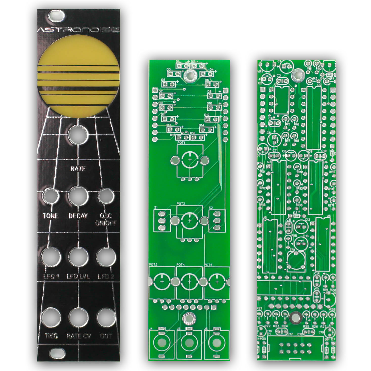
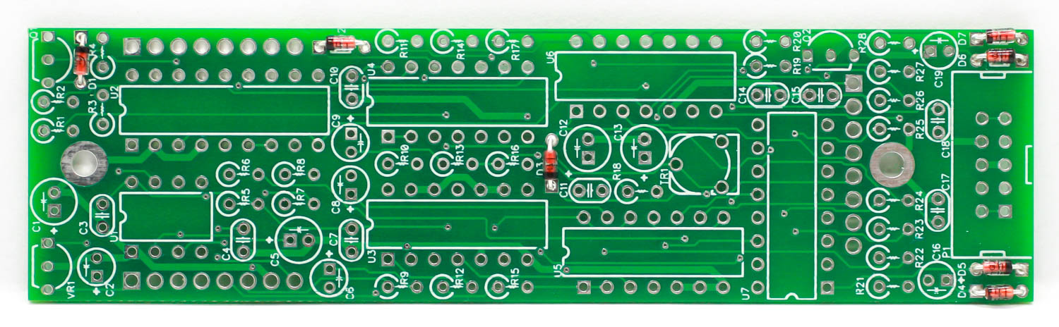
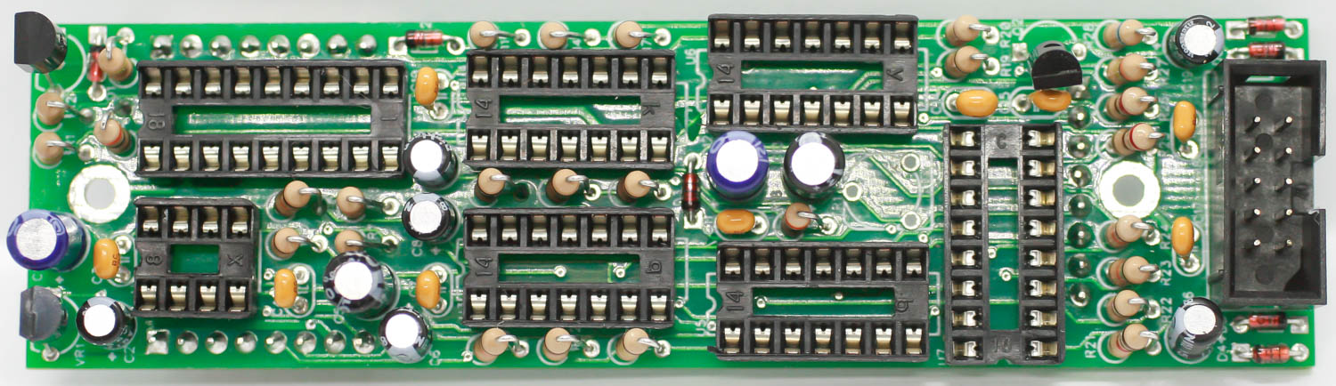
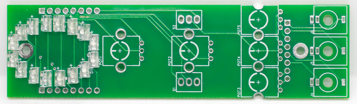
Astronoise Eurorack PCSs and Panel
Logic Board Diodes
The diodes are polarized, so make sure to populate them with the cathode stripe in the same direction as indicated by the silkscreen.
Once everything is in place, carefully flip your project over and solder the components in place. Clip any excess leads on the bottom of the board.
Astronoise Eurorack Diodes
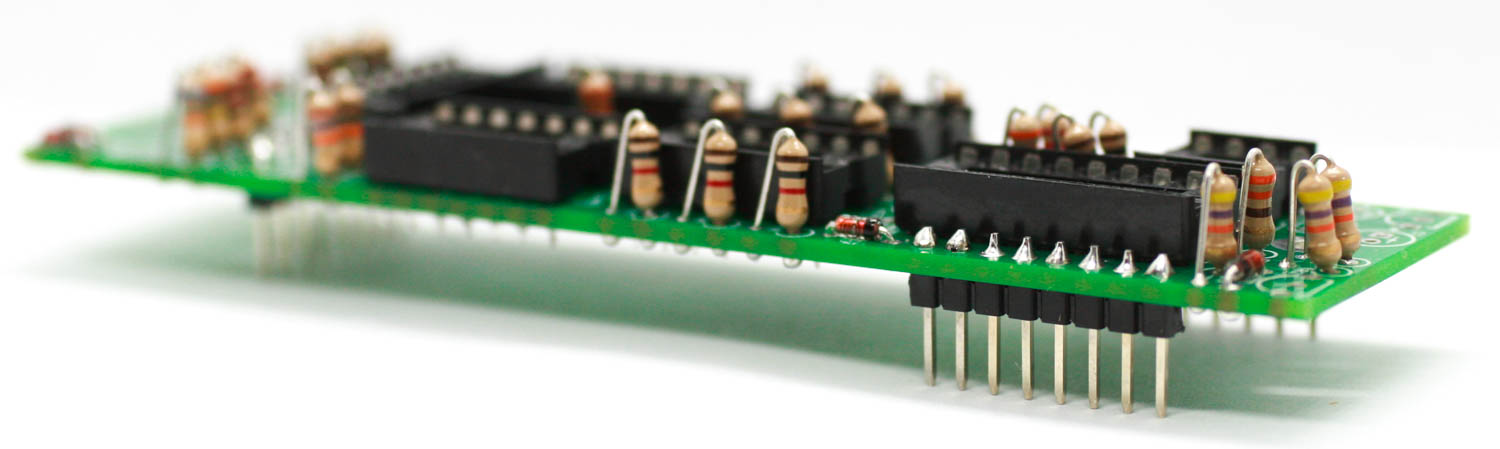
Logic Board IC Sockets
Next up are the IC sockets. Take care when populating these to not bend any of the legs. Line up the notch at the end of the socket with the notch on the silkscreen. This notch indicates where pin 1 of the IC is. When you have them populated, carefully flip your project over and solder everything in place.
A trick to getting these nice and flat is to only solder one or two pins of each socket, and then reflow the solder joint while gently pushing on the top of the socket to seat it flat against the PCB. Then continue on and solder the rest of the pins.
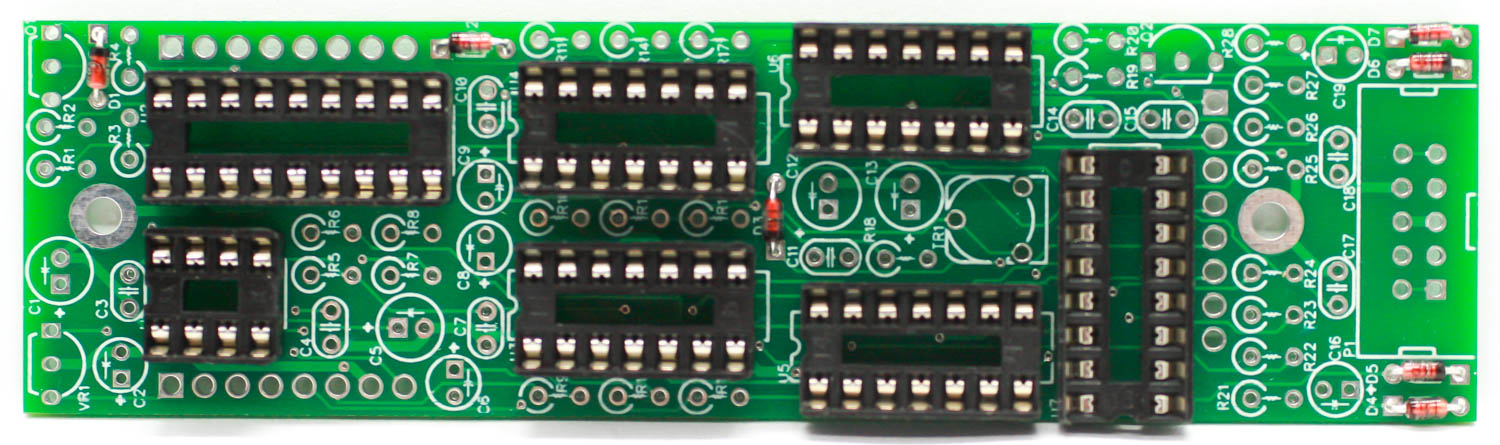
Astronoise Eurorack IC Sockets
Logic Board Male Header Pins
Place the MALE header pins into the PCB as shown below. Carefully turn the PCB over (try using the control board to hold the headers on) and solder the pins in place.
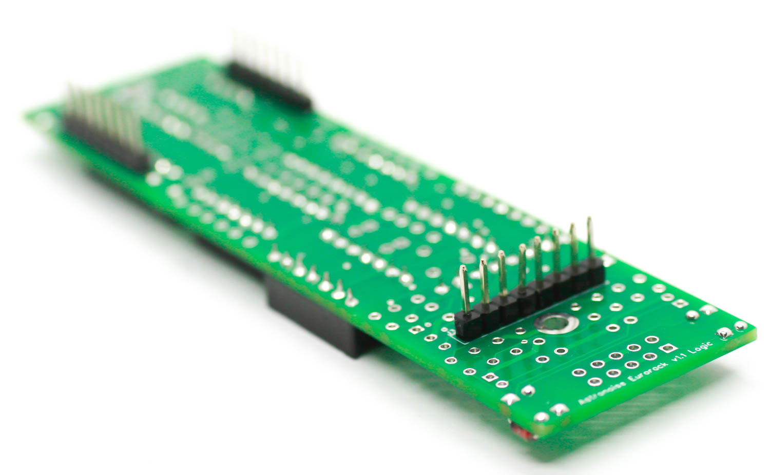
Astronoise Eurorack Header Pins
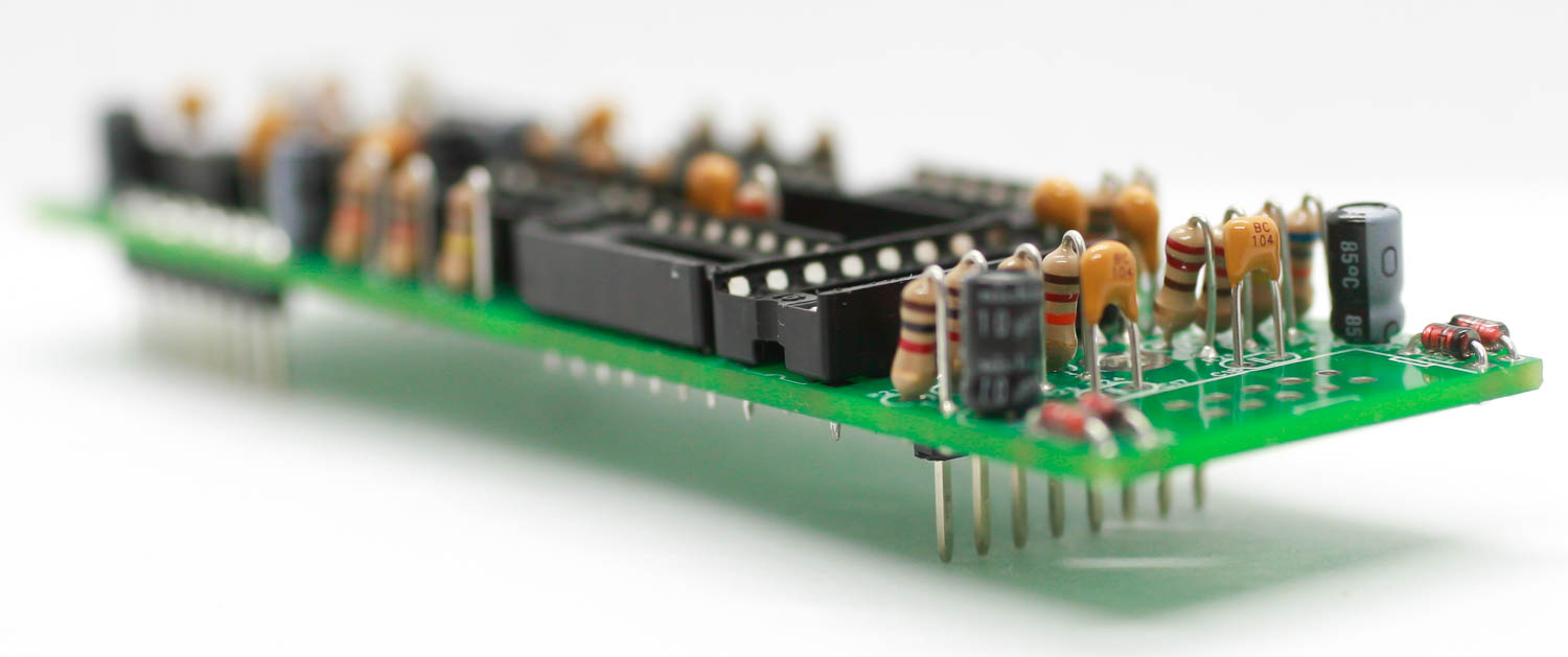
Logic Board Stand Up Resistors
Populate the resistors. Resistors are non-polarized, so it doesn’t matter which direction you put them on the PCB, but it will help with any troubleshooting that may arise if you line up all the tolerance bands. This will make it easier to read the color codes on the resistors. Bend the legs of the resistor over, then place it on the board.
Once everything is in place, carefully flip your project over and solder the components in place. Clip any excess leads on the bottom of the board.
Astronoise Eurorack Standup resistors
Astronoise Eurorack Standup Resistors 1
Logic Board Capacitors
Now we can populate the ceramic capacitors. These are non-polarized and can be inserted either direction. If the capacitor coating runs down the legs a little, make sure the coating doesn’t poke into the pads. Once they are in, carefully flip over your project and solder them in place, clipping the excess leads.
The electrolytic capacitors are polarized, so take care! Ensure that the longer leg (the leg that is further from the stripe indicator on the body) goes through the solder pad with the little ‘+’ symbol next to it.
Once it is aligned properly, carefully flip your project over and solder it in place, clipping the excess leads on the bottom.
Astronoise Capacitors
Logic Board Power Socket & Transistors
Populate the transistors by aligning the flat side of the component with the flat side of the silk screen. Turn over and carefully solder.
Next up is the keyed shrouded power header. Make sure when populating this that the notch in the header is lined up with the notch designed on the silkscreen. Carefully turn over to solder.
Astronoise Eurorack Transistors & Power Header
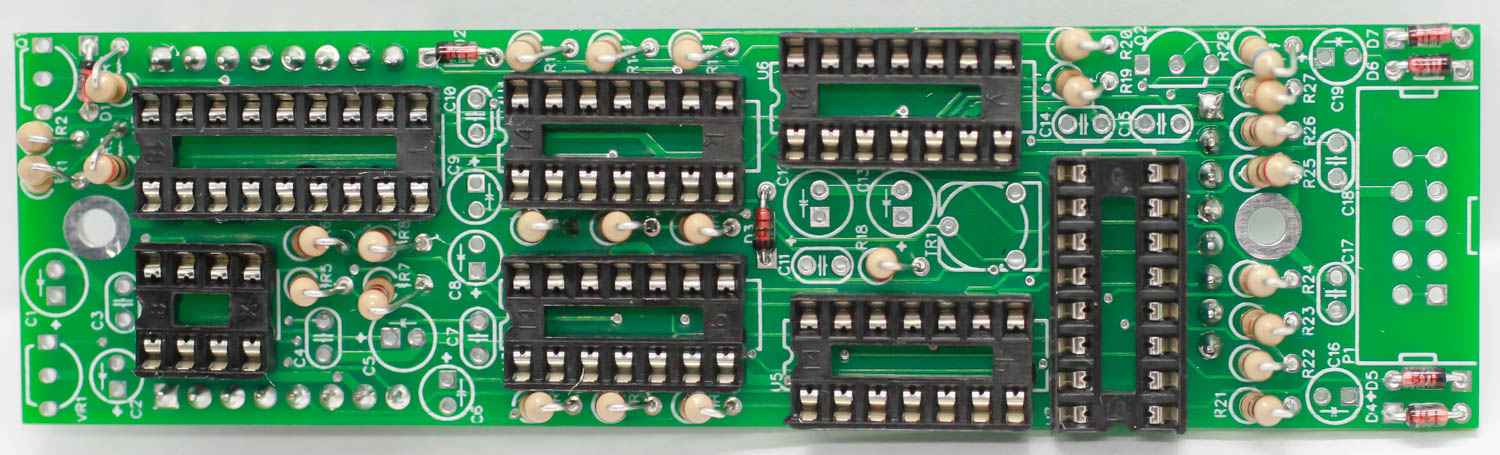
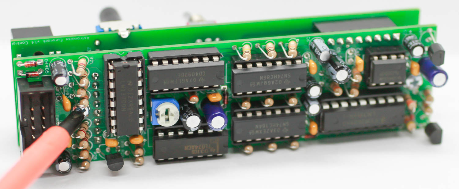
Logic Board Power Trimmer Resistor & ICs
Populate the trimmer resistor, carefully turnover and solder. Next carefully place the ICs into the sockets by (just barely!) bending in the ICs and aligning with the notch on the socket and silkscreen.
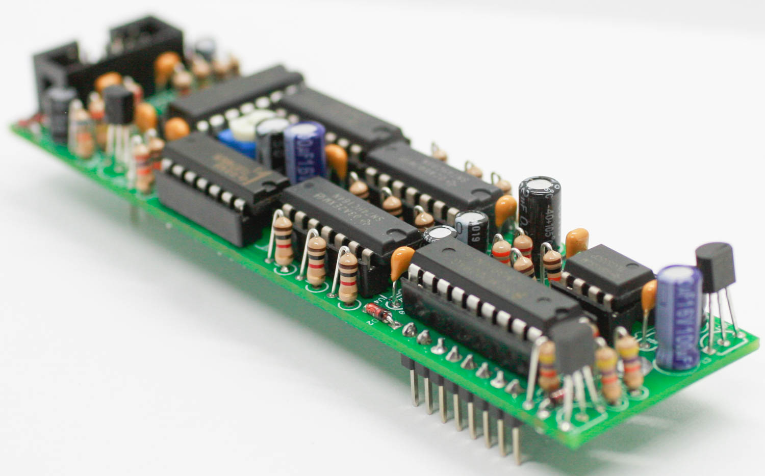
Astronoise Eurorack IC’s & trimmer resistor
Control Board Power LEDs
Populate the LEDs by placing the LONGER lead into the pad that has a “+” next to it. Place them flat, and carefully turn over to solder. Clip excess leads.
Astronoise Eurorack LEDs
Control Board Header Sockets
Place the FEMALE header pins into the PCB as shown below. Carefully turn the PCB over (try using a piece of cardboard to hold the headers on) and solder the pins in place. Alternatively, you can connect the sockets to the headers on the main board and place the control board on top of the socket pins (must make sure the sockets are on the correct side of the board).
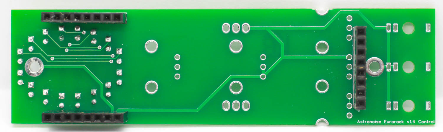
Astronoise Eurorack Header Sockets
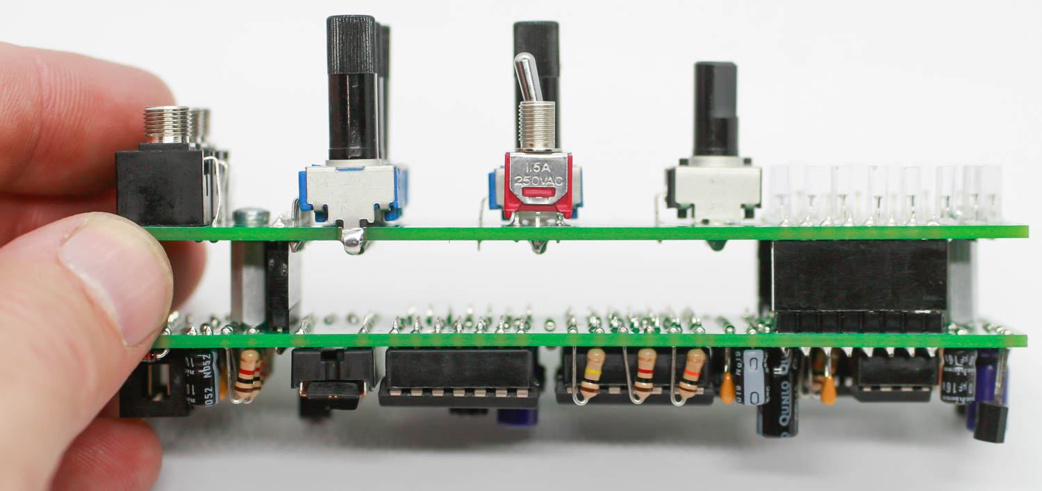
Control Board Jacks, Switches and Pots.
First place the jacks into the pcb, flip and solder. Then place the switches in the PCB, flip and solder and then put the pots into the PCB as show below. Make sure that the D Shaft Pot is placed just below the LEDS!!
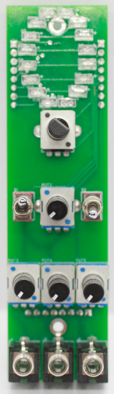
Control Board Pots, Jacks & Switches
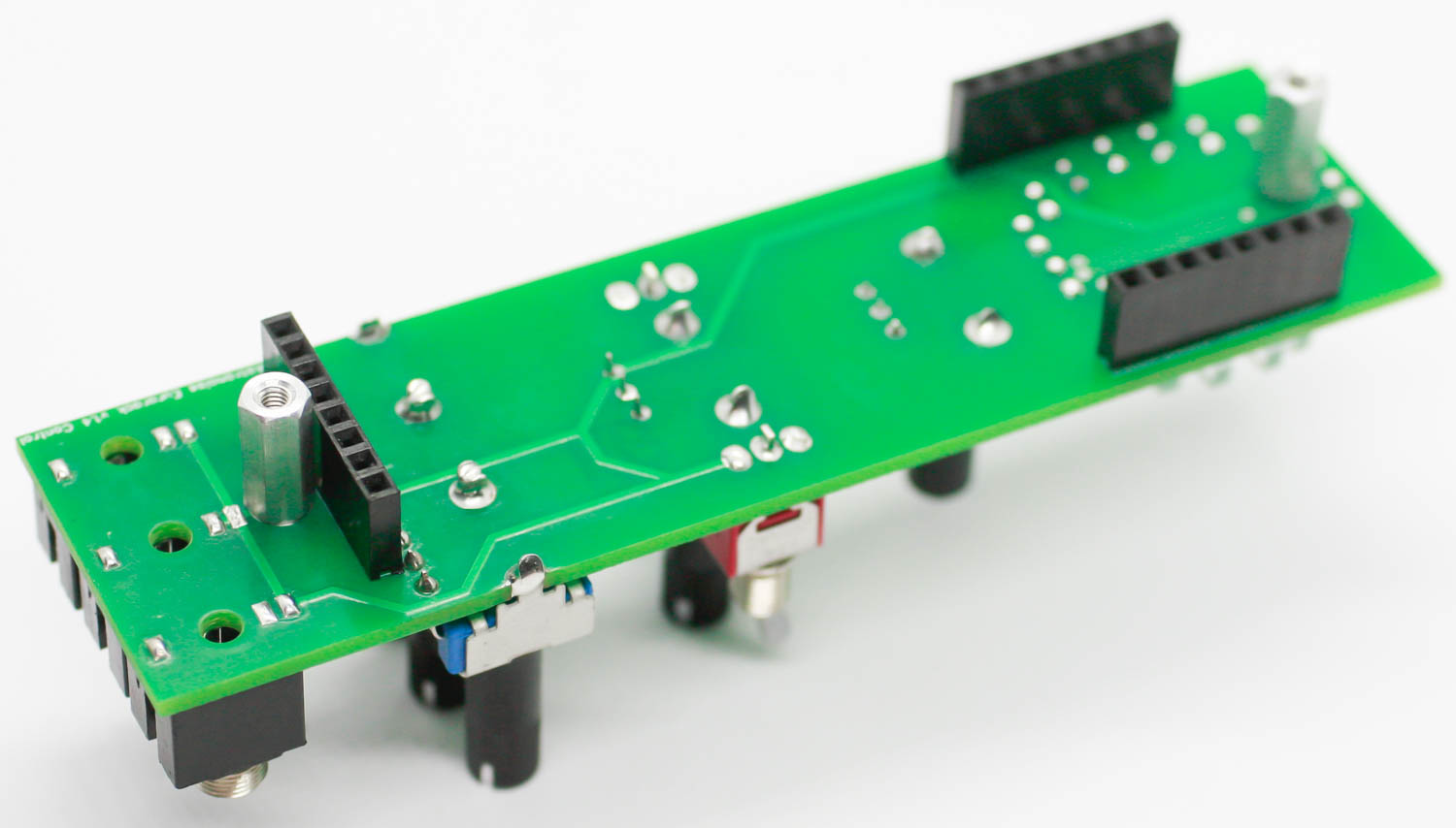
Control Board Standoffs
Screw in the standoffs on the control board as shown below.
AstroNoise Control Board Standoffs
Now carefully connect the main board to the control board and screw the main board to the standoffs.
Astronoise Eurorack Board Placement
Astronoise Eurorack standoffs
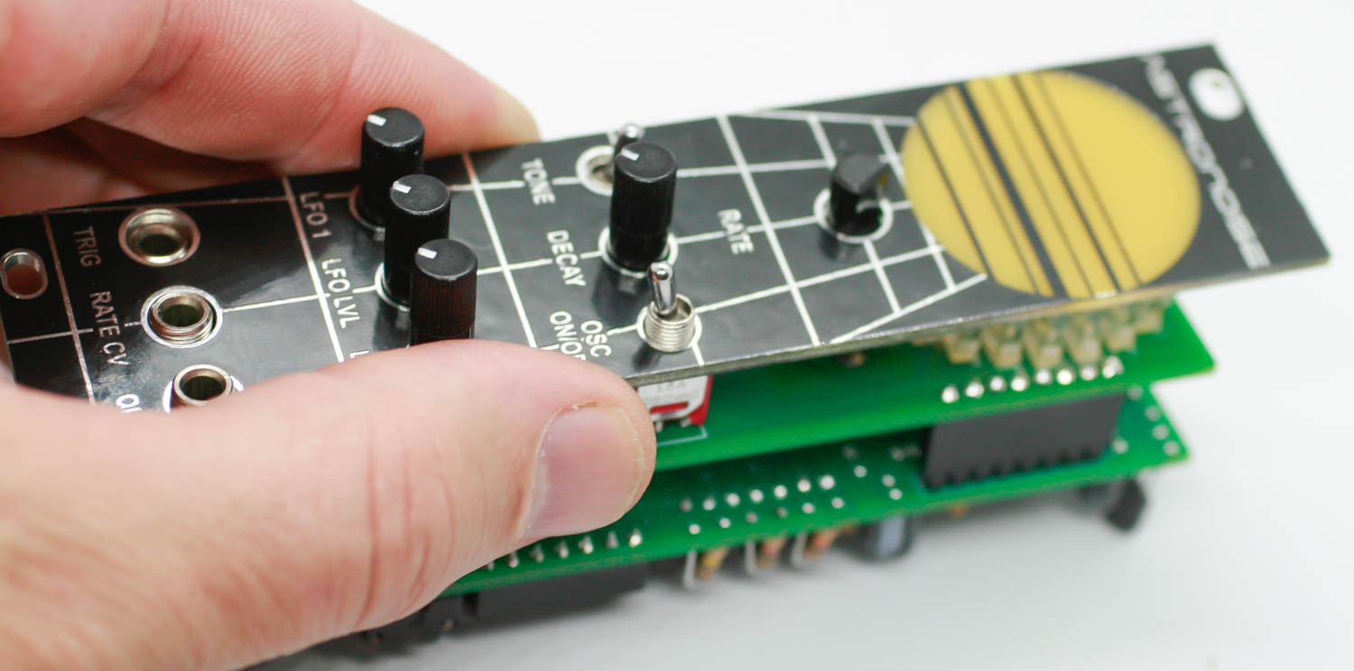
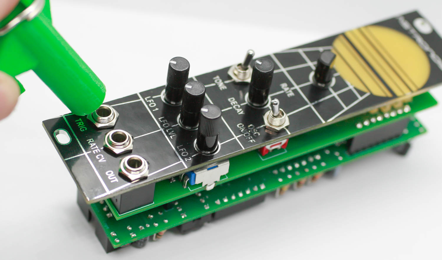
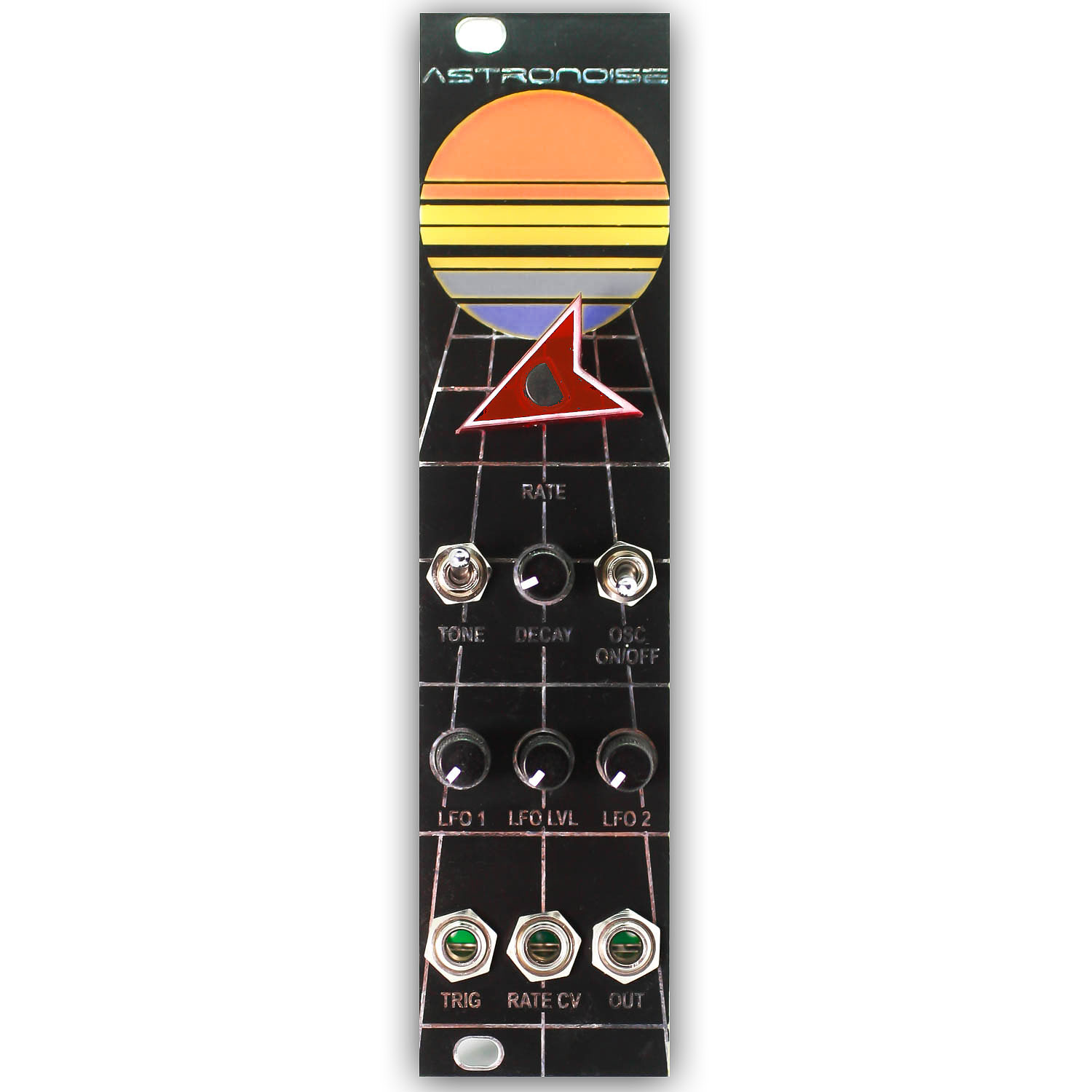
Panel Placement
Place the panel over the control board components & gently tighten the switch and jack nuts.
Astronoise Eurorack Panel Placement
Astronoise Eurorack Panel Placement 2
Take the custom “spaceship” knob and place it on the D shaft pot. You may need to give it just a little force , but it will pop on.
Spaceship Knob
Congrats, your project is ready to be tested!
Astronoise Eurorack Final Build