


Important Links
Product Page
Store Page
Assembly Instructions
Bill of Materials
Schematic
Capacitor & Resistor Lookup Guide
Mean Screamer WIRED Assembly Instructions

Mean Screamer Clone PCB
Thank you for purchasing a Mean Screamer Wired Kit. If you are looking to build this kit into a compact 1590B sized metal project box, please consult our PCB Mount version of this kit. Please follow these instructions in order, as it can be tricky to build and insert into the enclosure.
RESISTORS, CAPACITORS and SOCKETS
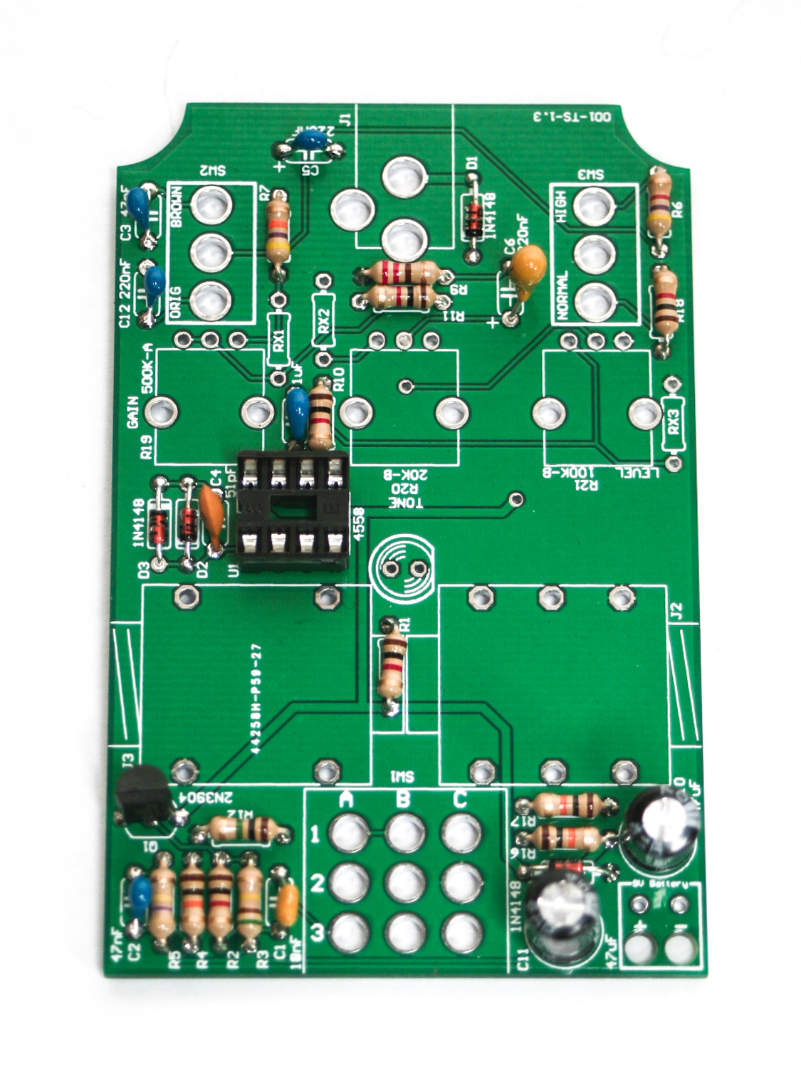
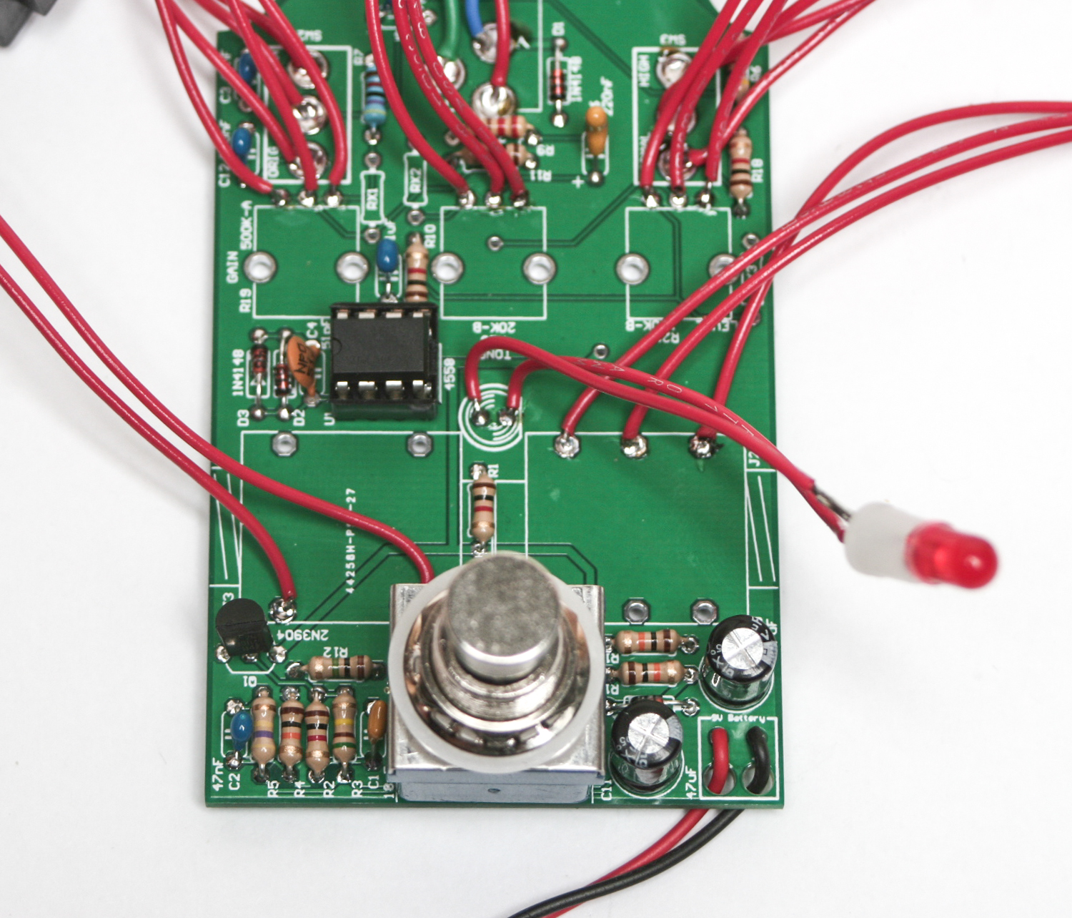
PCB Mean Screamer Resistors, Capacitors and Sockets
Please consult the BOM prior to adding any component. While we try to keep the same looking components in stock, variations of appearance will happen. Do not rely on the photos alone. If you need help reading components, check out our resistor and capacitor code charts in the menu at the top of the page. C6 is a Tantalum Capacitor and is Polarized, so you will need to insert the longer lead into the mounting hole with the “+” indicator on it. Add all of the Resistors, Capacitors and the 8 Pin Socket to the PCB, solder and carefully trim your leads.
3PDT STOMP SWITCH
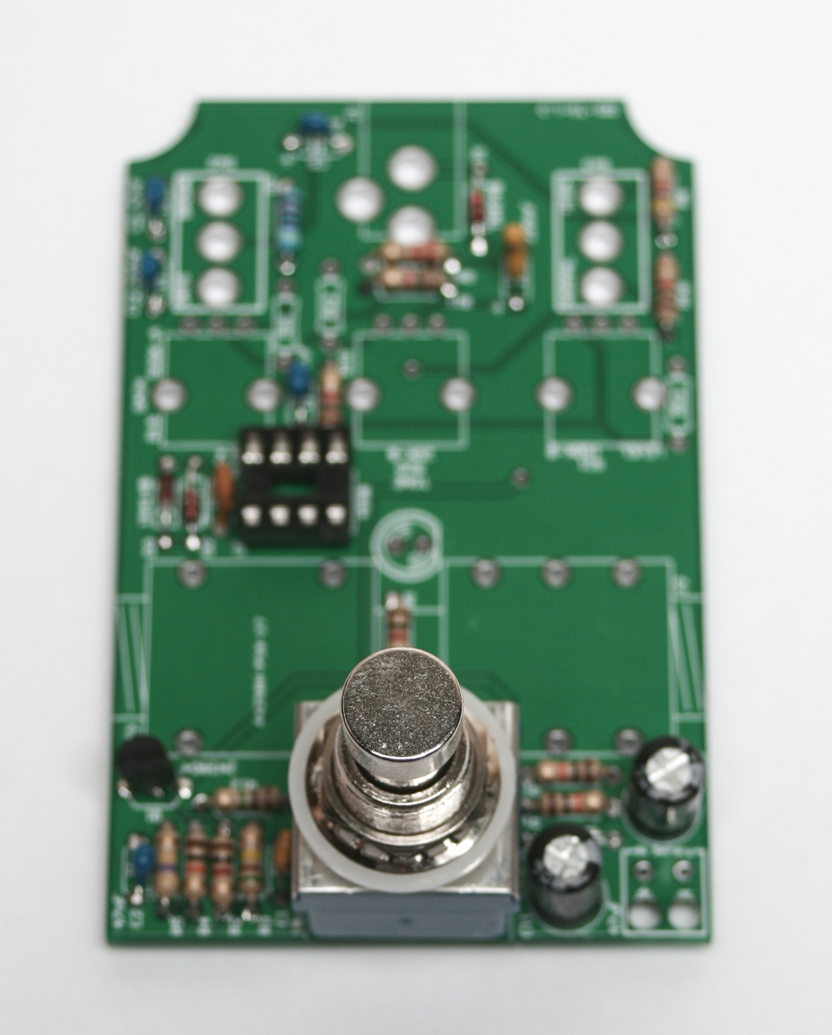
Mean Screamer 3PDT switch
Next, add the 3PDT stomp switch and the mono & stereo audio jacks.
WIRING
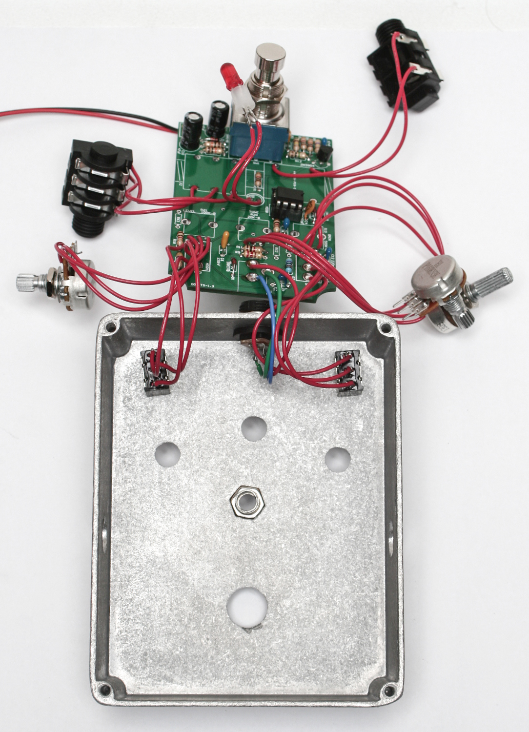
Wire the LED, switches, pots, and jacks as shown below. If you have metal audio jacks in your kit, please follow the next two photos.
Now clip 23 wires to suit the distance to the mounting holes on your enclosure and solder them to all of the wired components, as shown above. Make sure to add the plastic bezel holder onto the LED as shown BEFORE you solder the wires on.
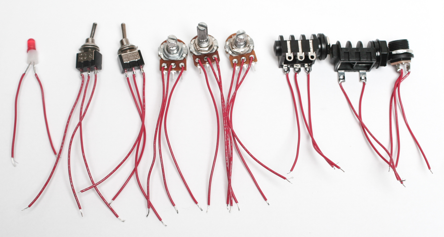
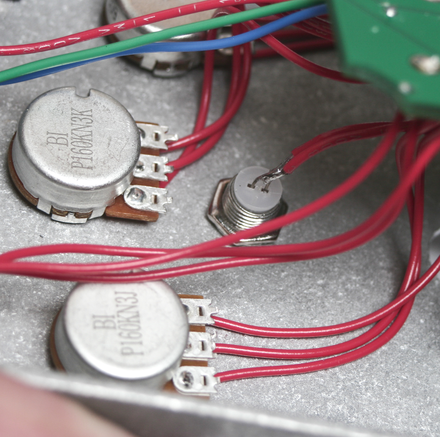
Wiring Components
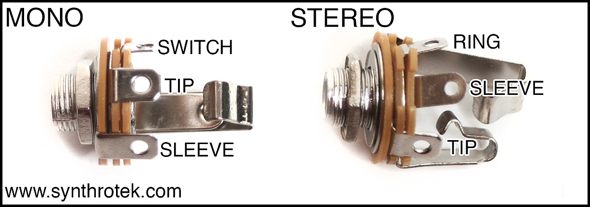
1/4″ Metal Audio Jack Wiring
For this kit, you will only need to use the TIP and SLEEVE connections on the MONO jack. Connect the wires using the diagram below:
TIPS, RING and SLEEVES
WIRING THE DC POWER JACK
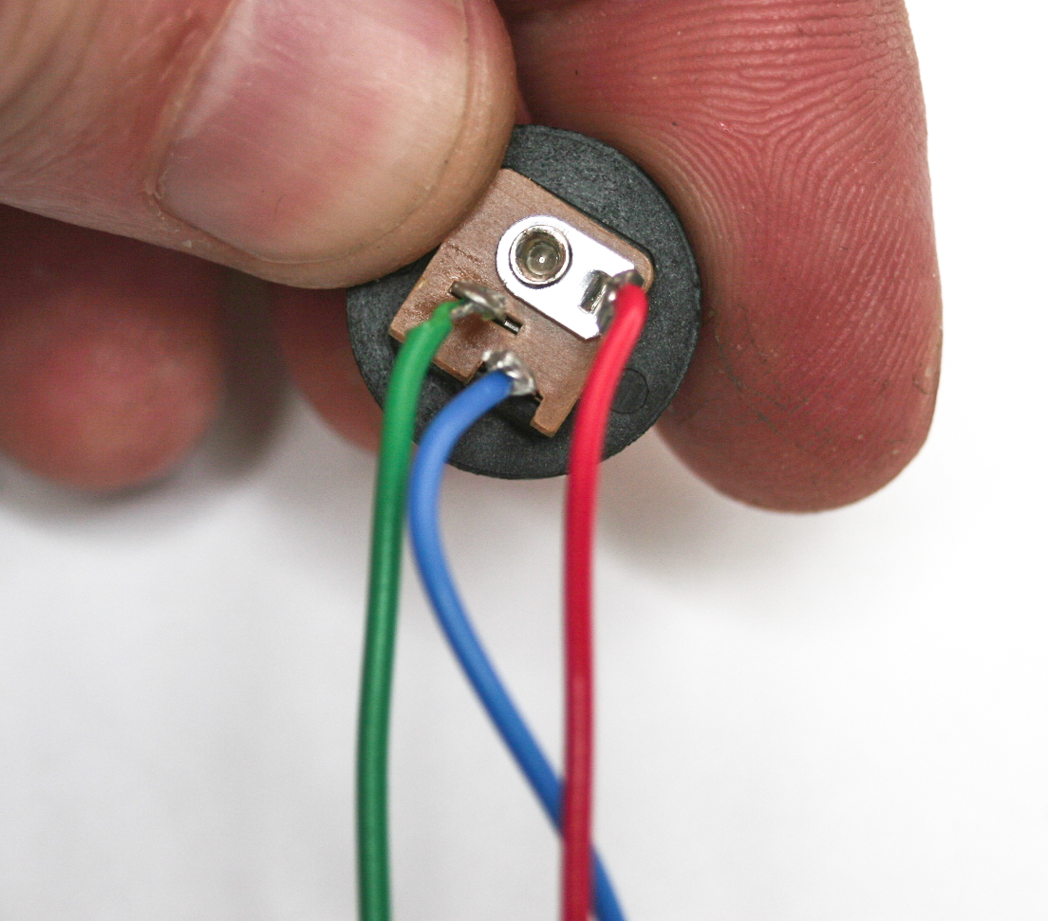
Please follow the above photo (you do not need the colors, they are just there for easy identification) as you wire your dc jack.
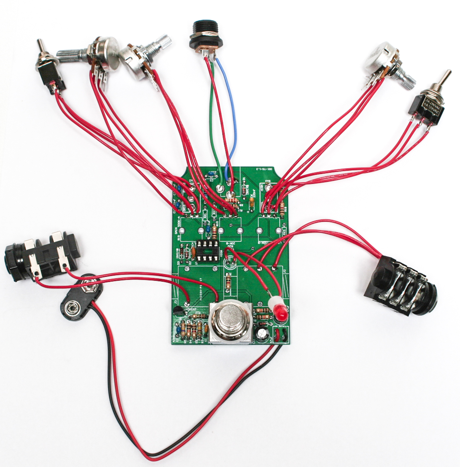
Mean Screamer all wires
You can now add the remaining wired components to the PCB
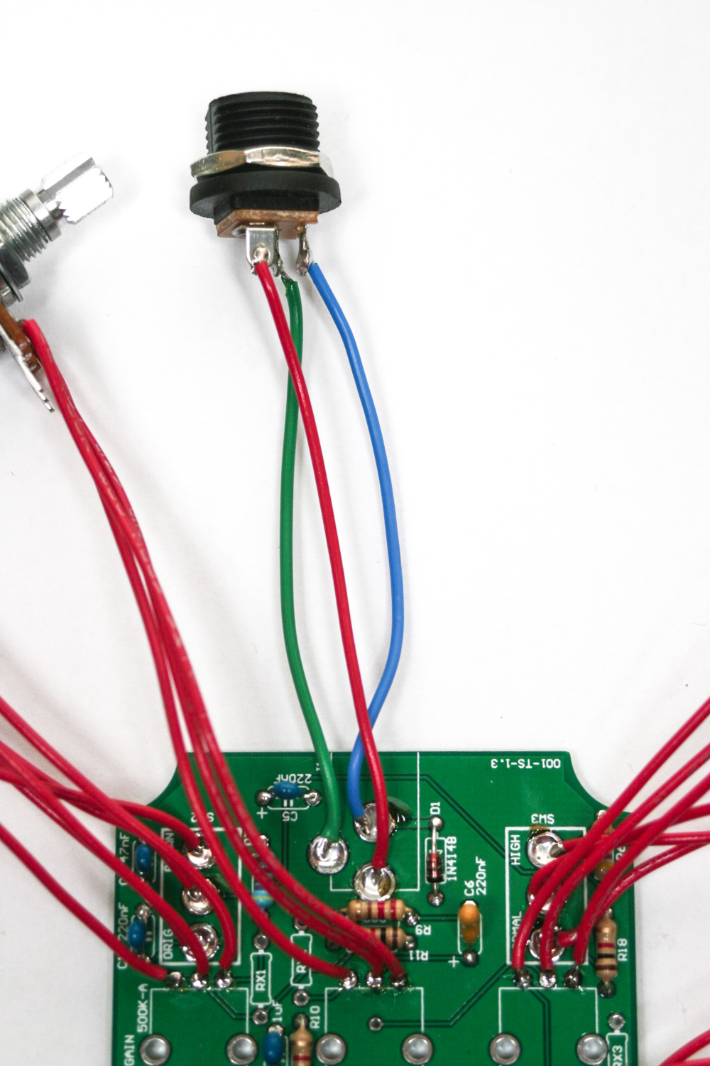
wiring dc jack to pcb
Above shows which solder points to connect the wires to the DC jack.
Add IC
You can now add the IC and test your product prior to going into the enclosure. Rock out!
ENCLOSURE
Inserting switches in the to enclosure
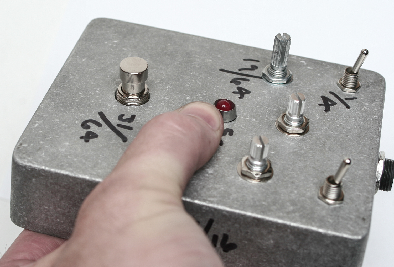
If you purchased our predrilled enclosure please follow these instructions precisely if possible. If you are using your own custom enclosure, do what seems best.
First put the DC jack and the 2 SPDT switches into their respective holes and tighten down nuts.
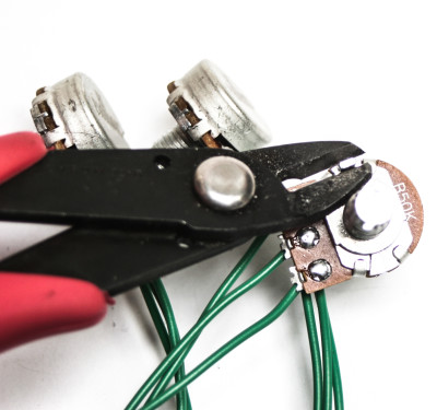
Trimming Pot Nubs
Make sure you trim off the alignment nubs on your pots before inserting into your case. This will keep the pots mounting flush and not ‘wanky’.
Pots and LED
Next add the pots top the enclosure and tighten down as well. Then push in the LED into the Bezel.
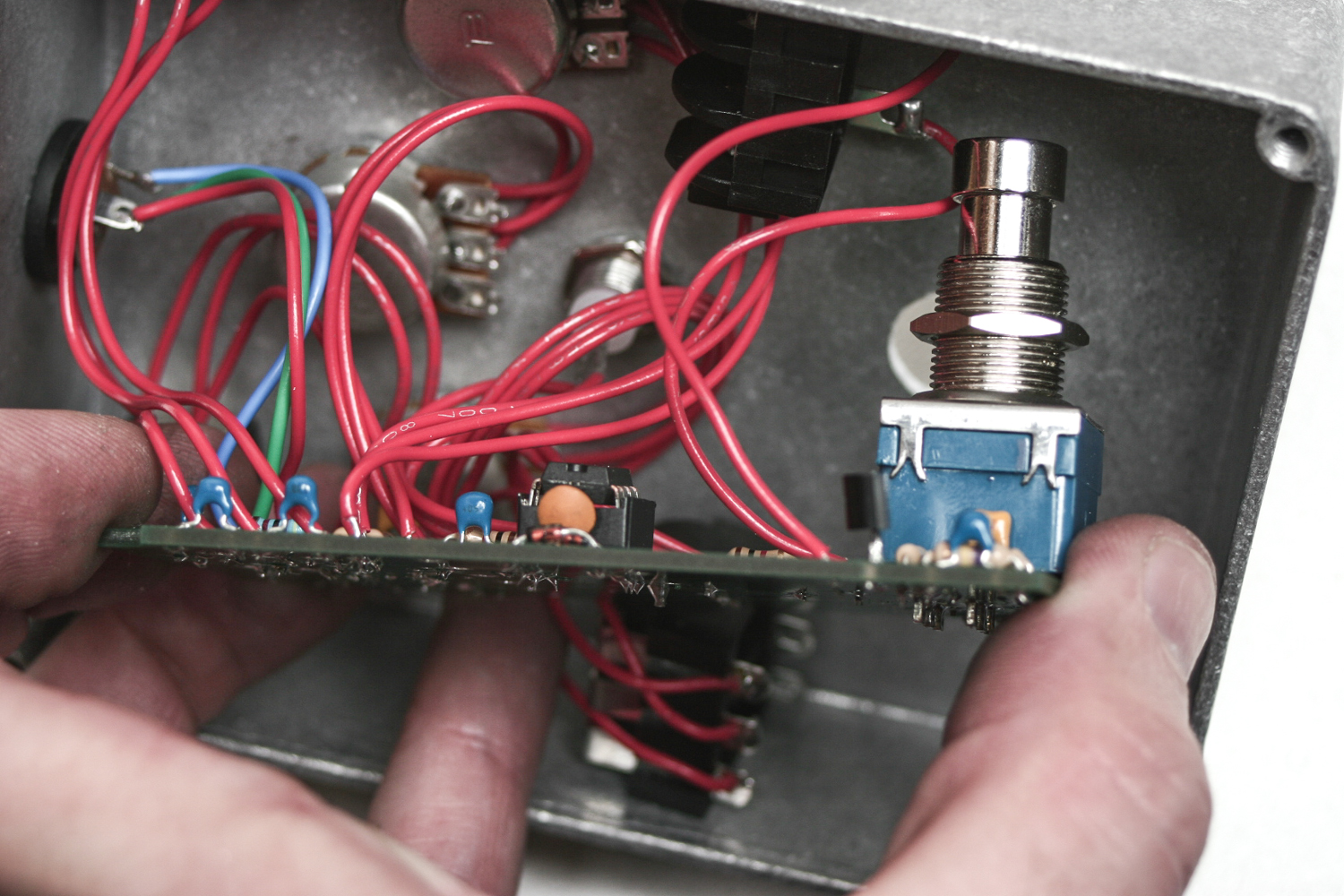
3PDT Stomp Switch Nut
Put the securing nut on the shaft about half way up before putting the switch into the enclosure. This will need to be done to keep the PCB parallel and right over the audio jacks.
Push 3PDT tight to enclosure
Next, push the 3PDT switch through the case and tighten nut down. You can now screw on the back of the enclosure and get to making some siqqq sounds.
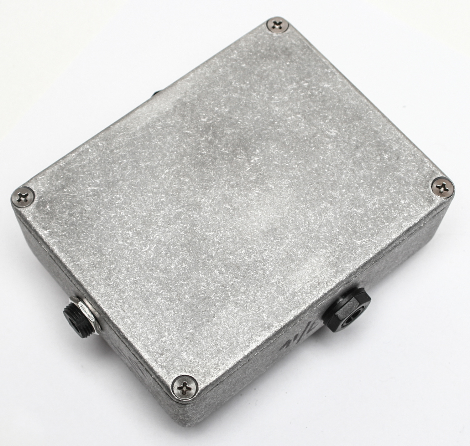
Screw Rear of Case
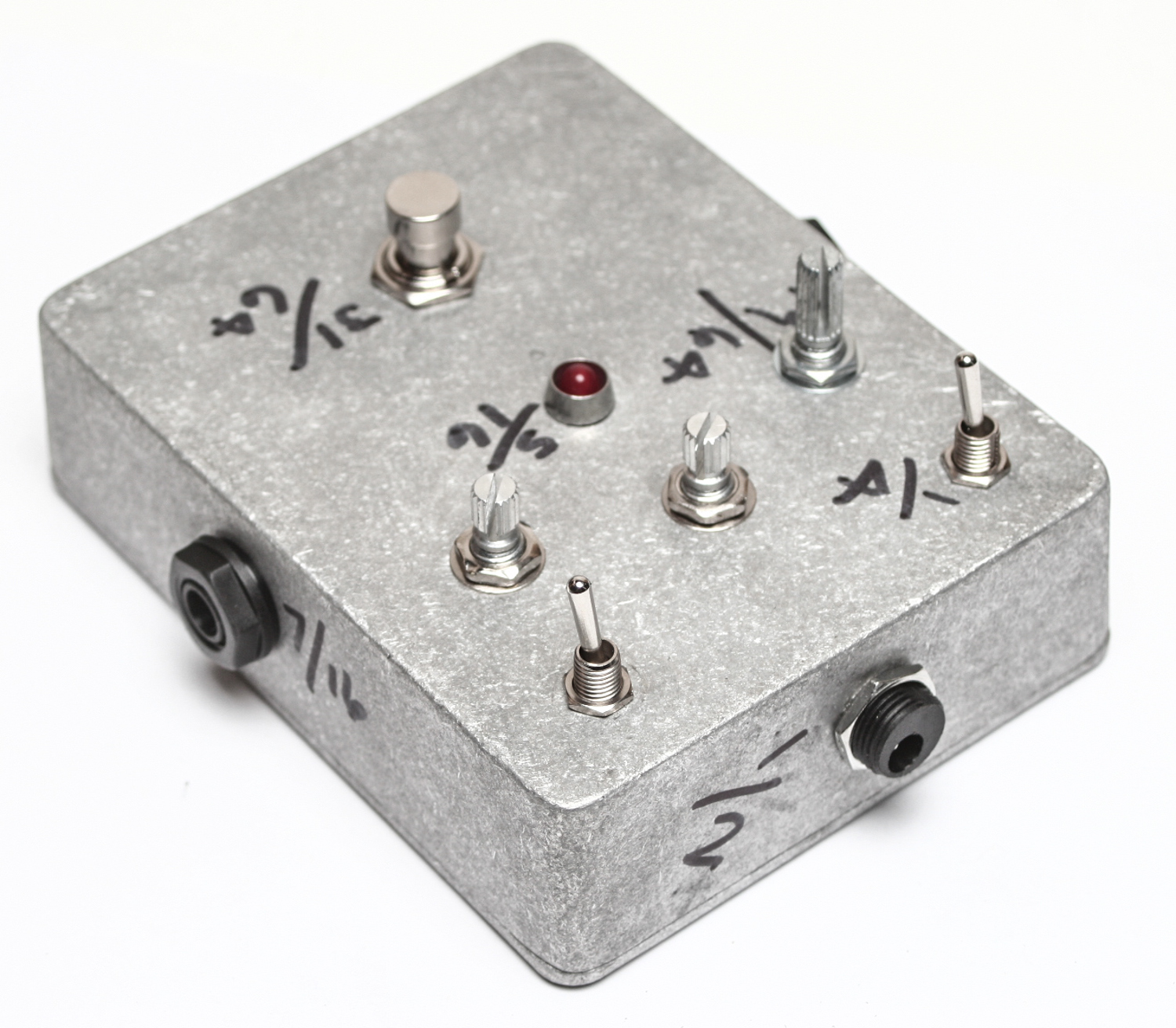
Final Mean Screamer Wired Build
Add knobs, graphics or fur to taste! Thanks for building this kit!