


Important Links
Product Page
Store Page
Quick Start Guide
Calibration Guide
Assembly Instructions
Bill of Materials
Capacitor and Resistor Lookup Guide
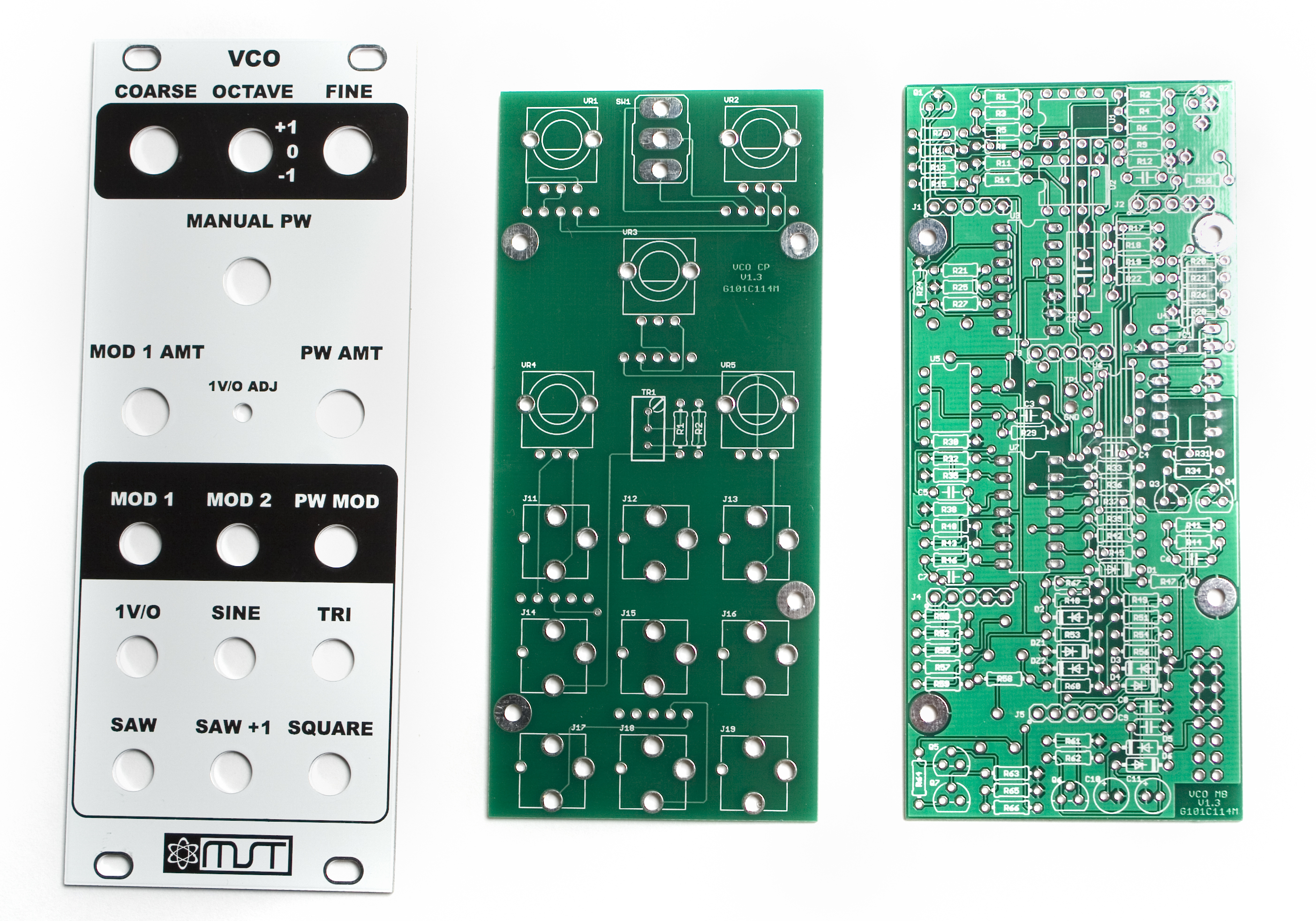
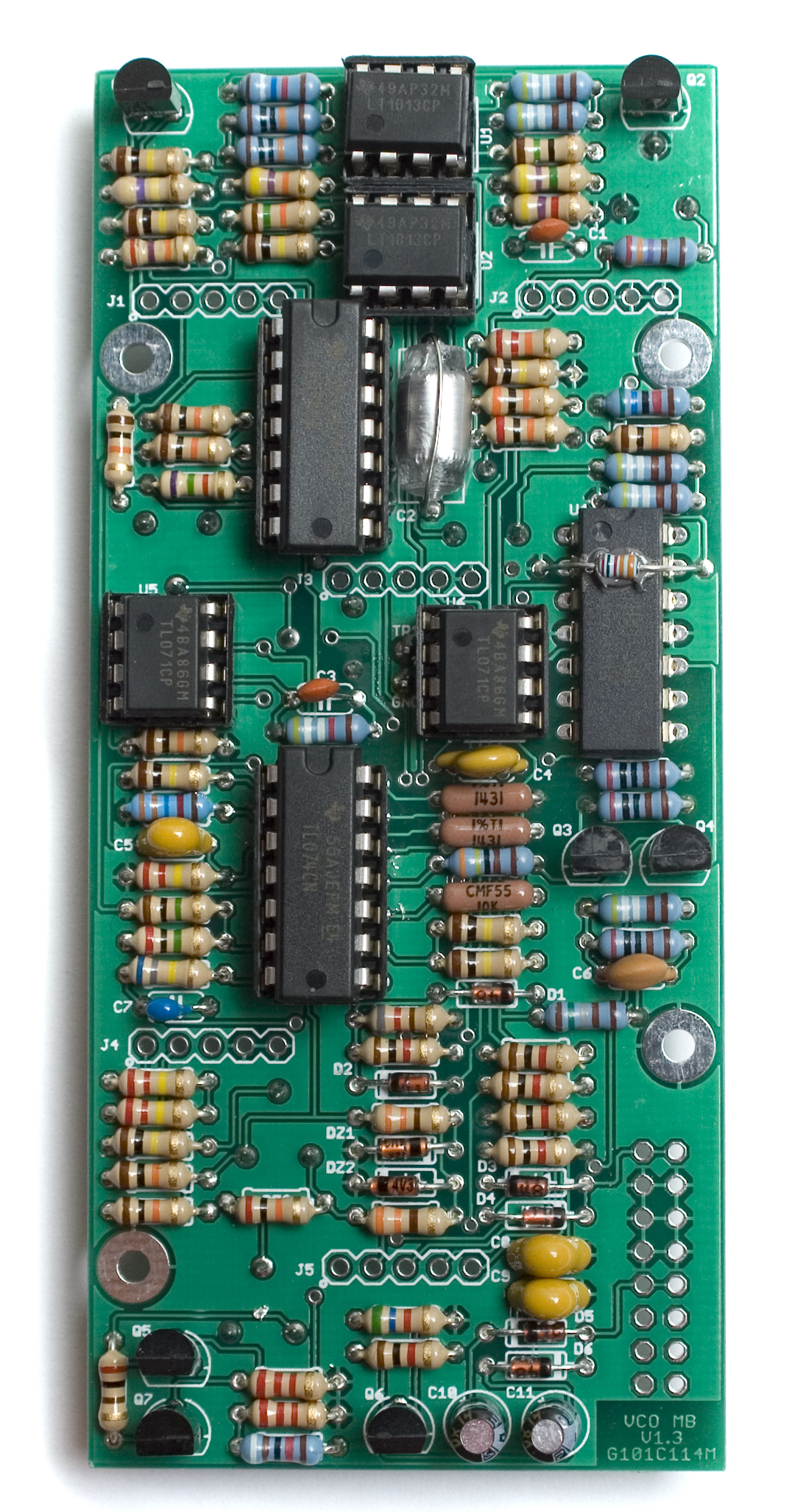
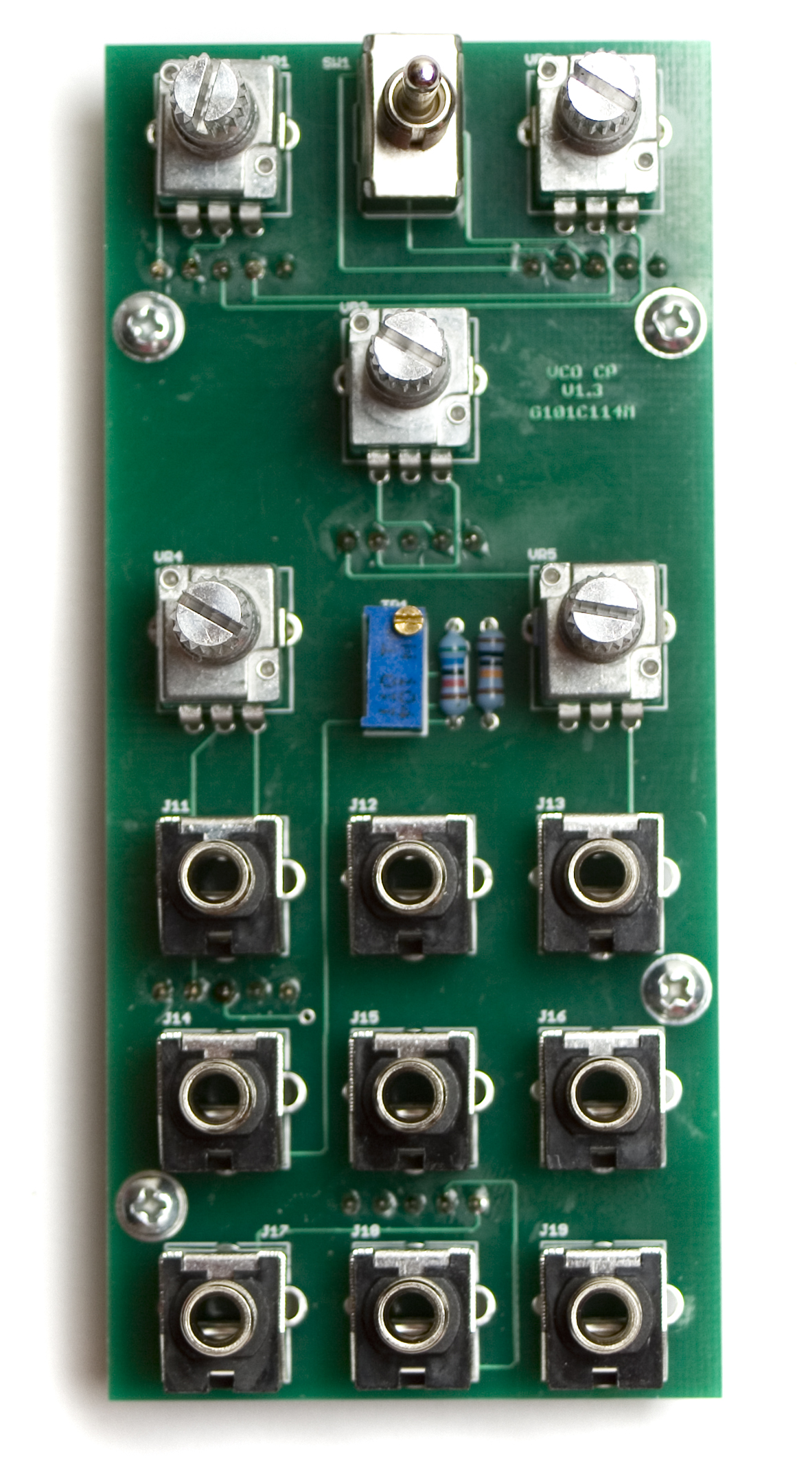
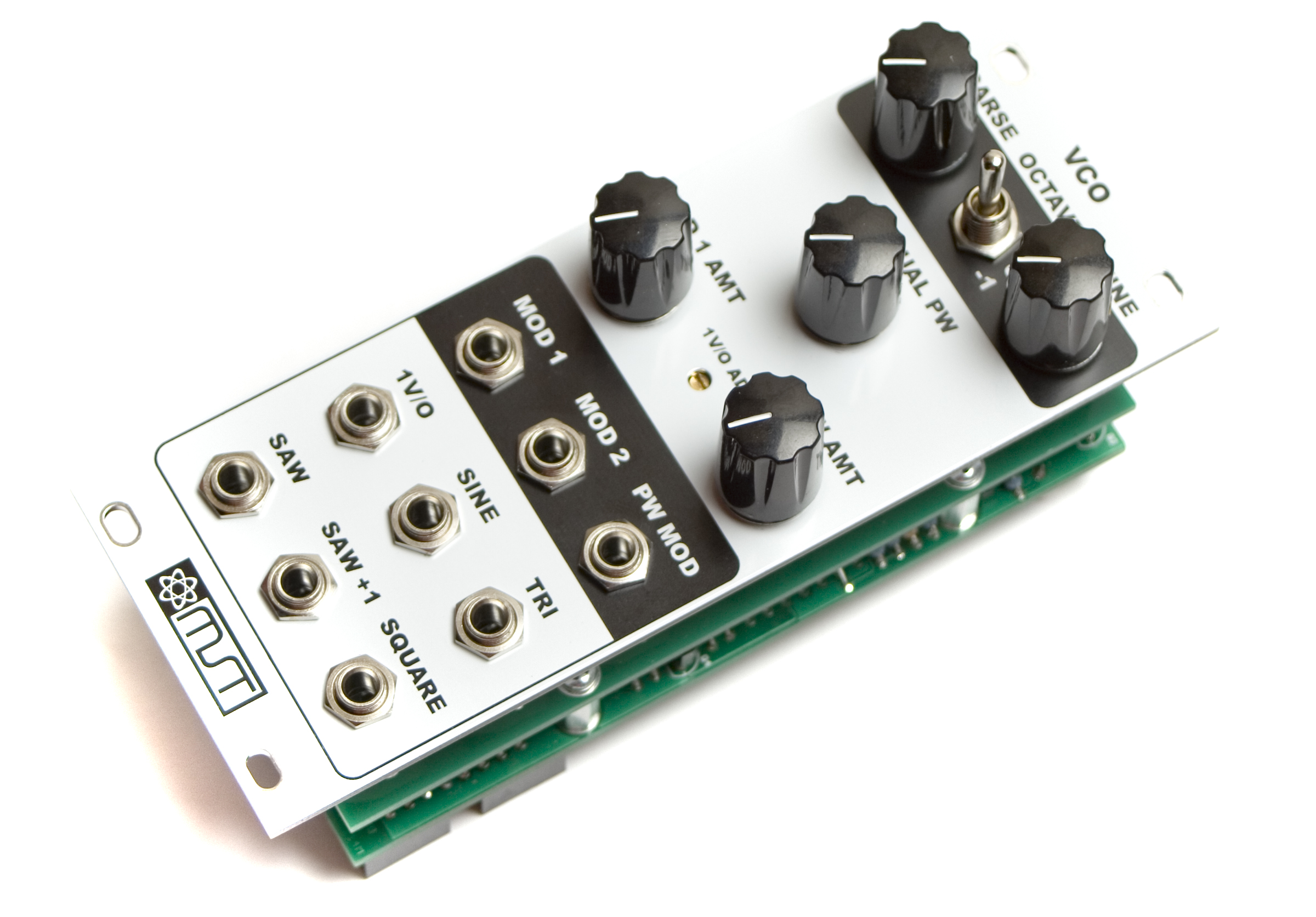
MST VCO PCB and Panel
Thank you for purchasing the MST VCO Eurorack module kit! This is a very advanced build. If you feel like you can handle it, please proceed! If not, get some help from a friend with experience or purchase a fully completed unit.
ATTN: Please follow the BOM and these instructions and don’t populate from the PCB or these instruction pictures alone. Also sometimes we cannot get the exact pictured components, so please look over your parts and check the codes first.
The MST VCO has some components that are temperature sensitive, so it is recommended to keep your soldering iron at or under 700*F.
Lets begin!
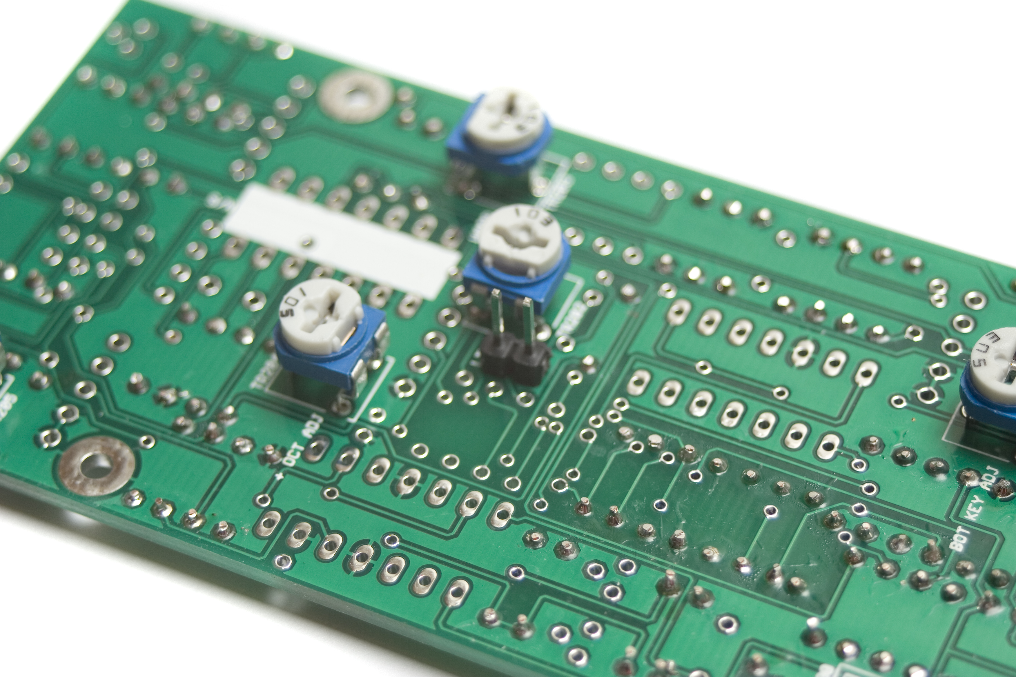
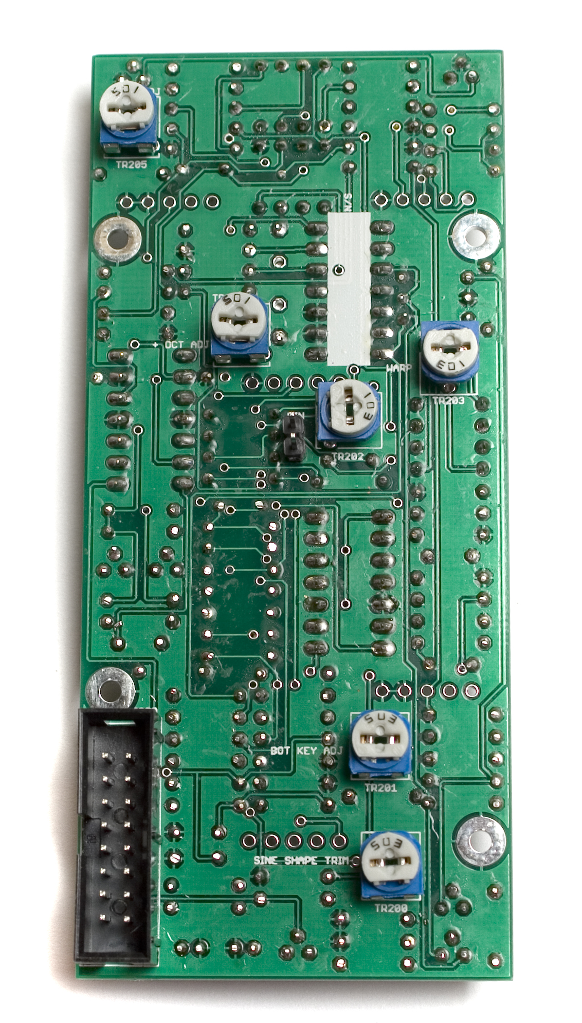
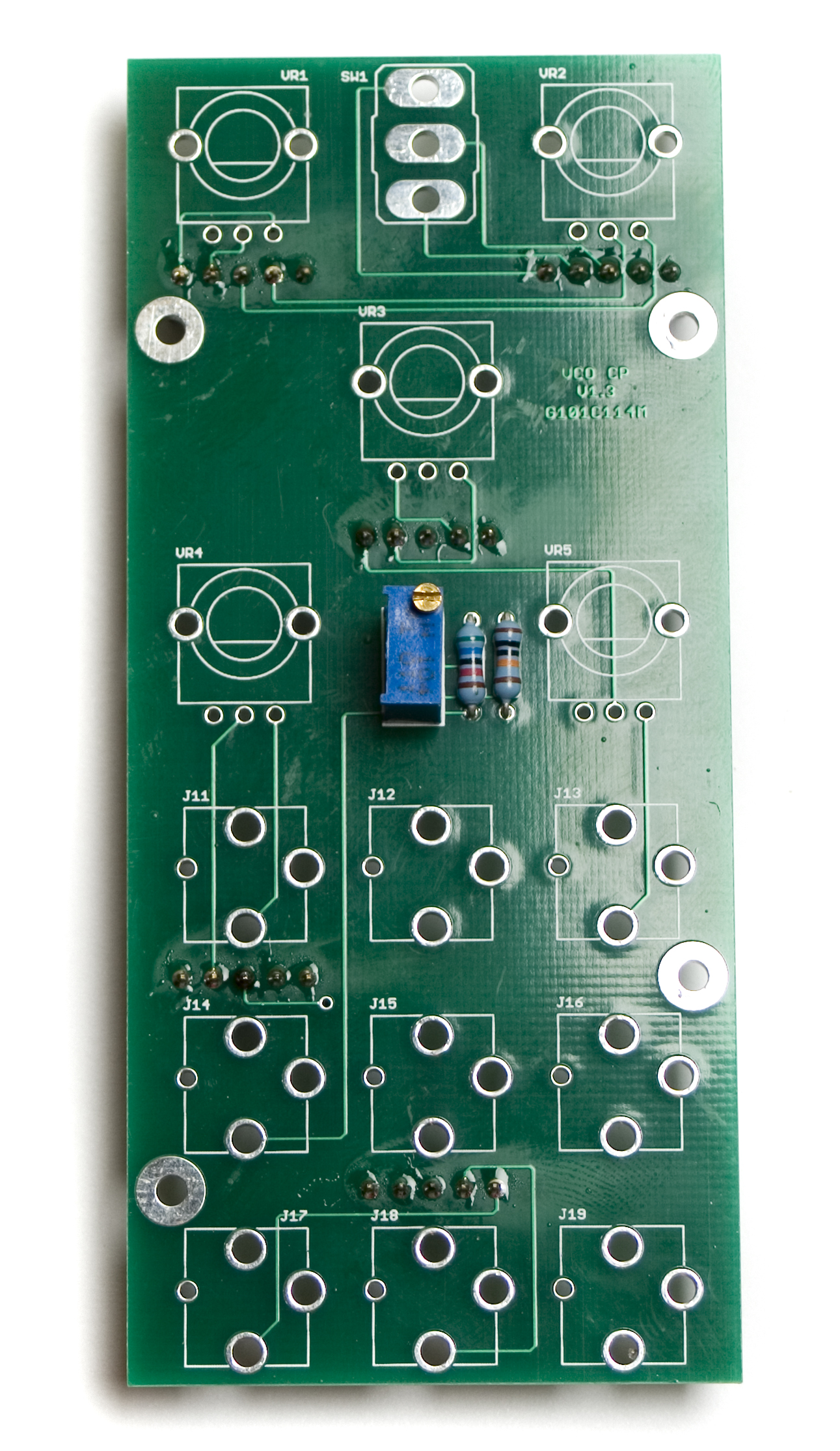
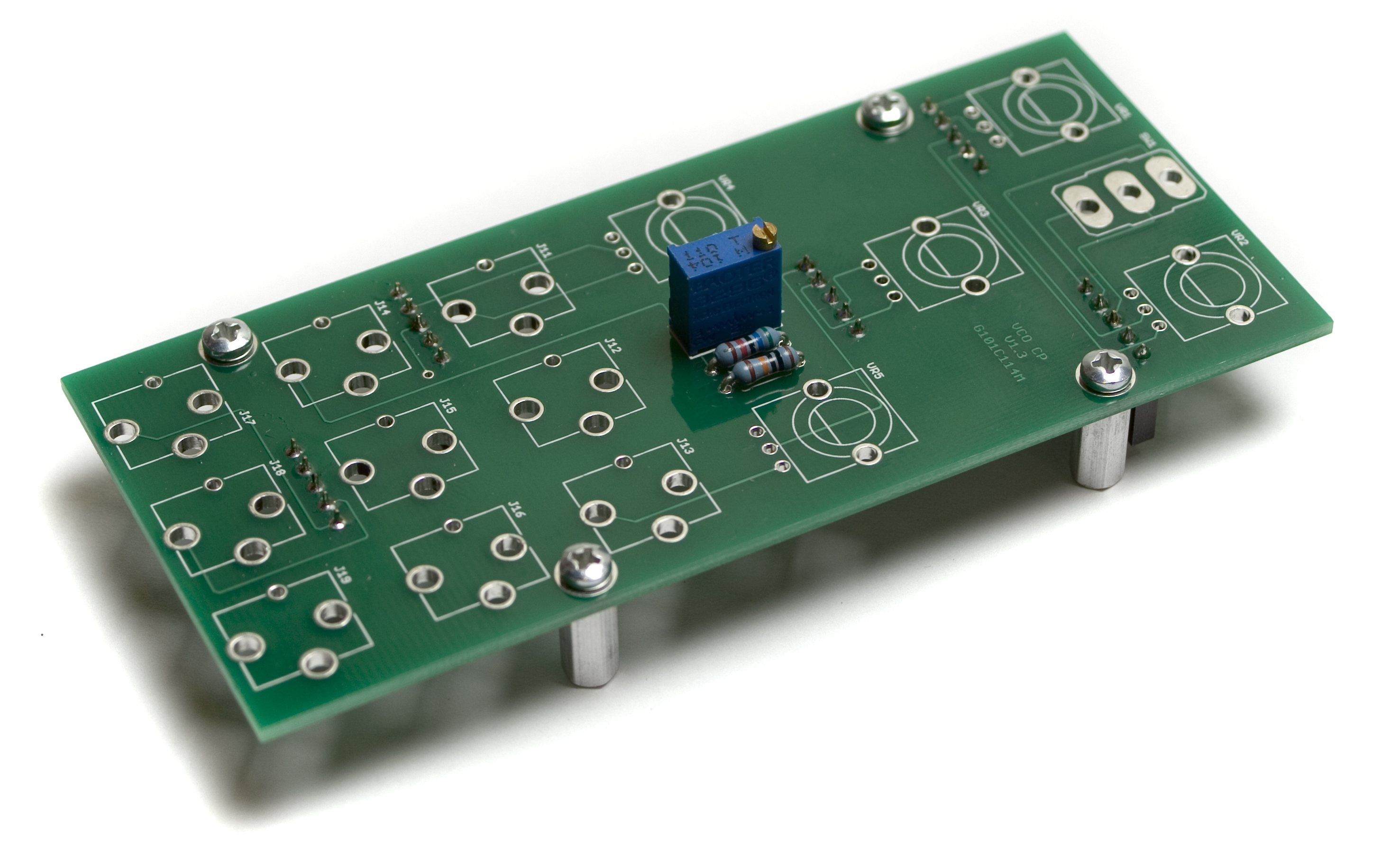
Trimmer Potentiometers
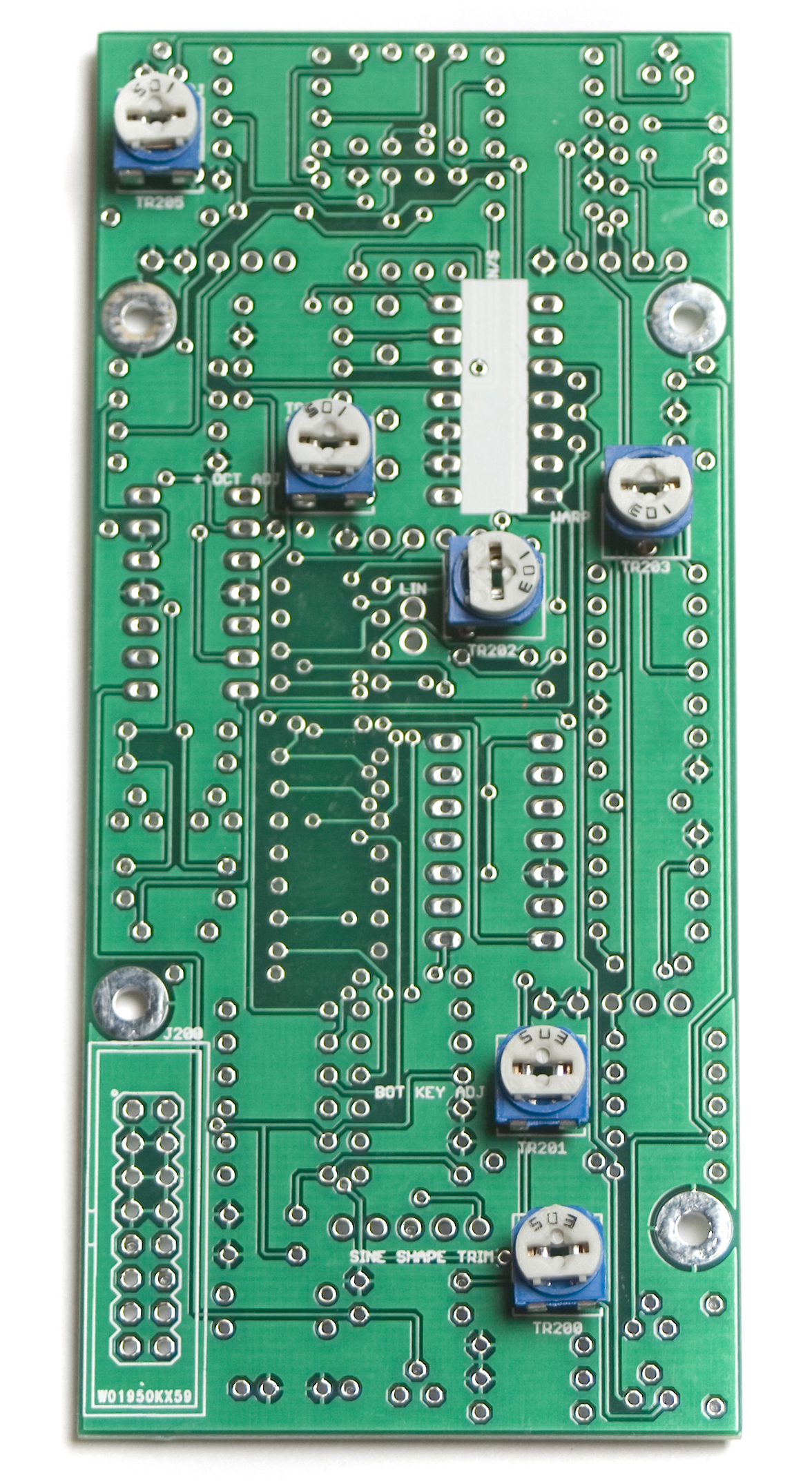
MST VCO Trimmer potentiometers
First up are the trimmer potentiometers on the main board. Insert the trimmers into their spots as shown above, and then flip your board over onto a hard, flat surface, and solder them in place.
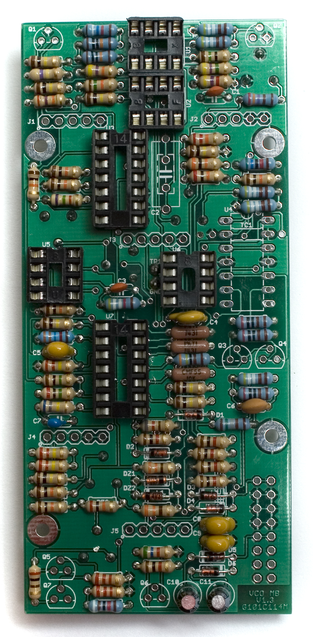
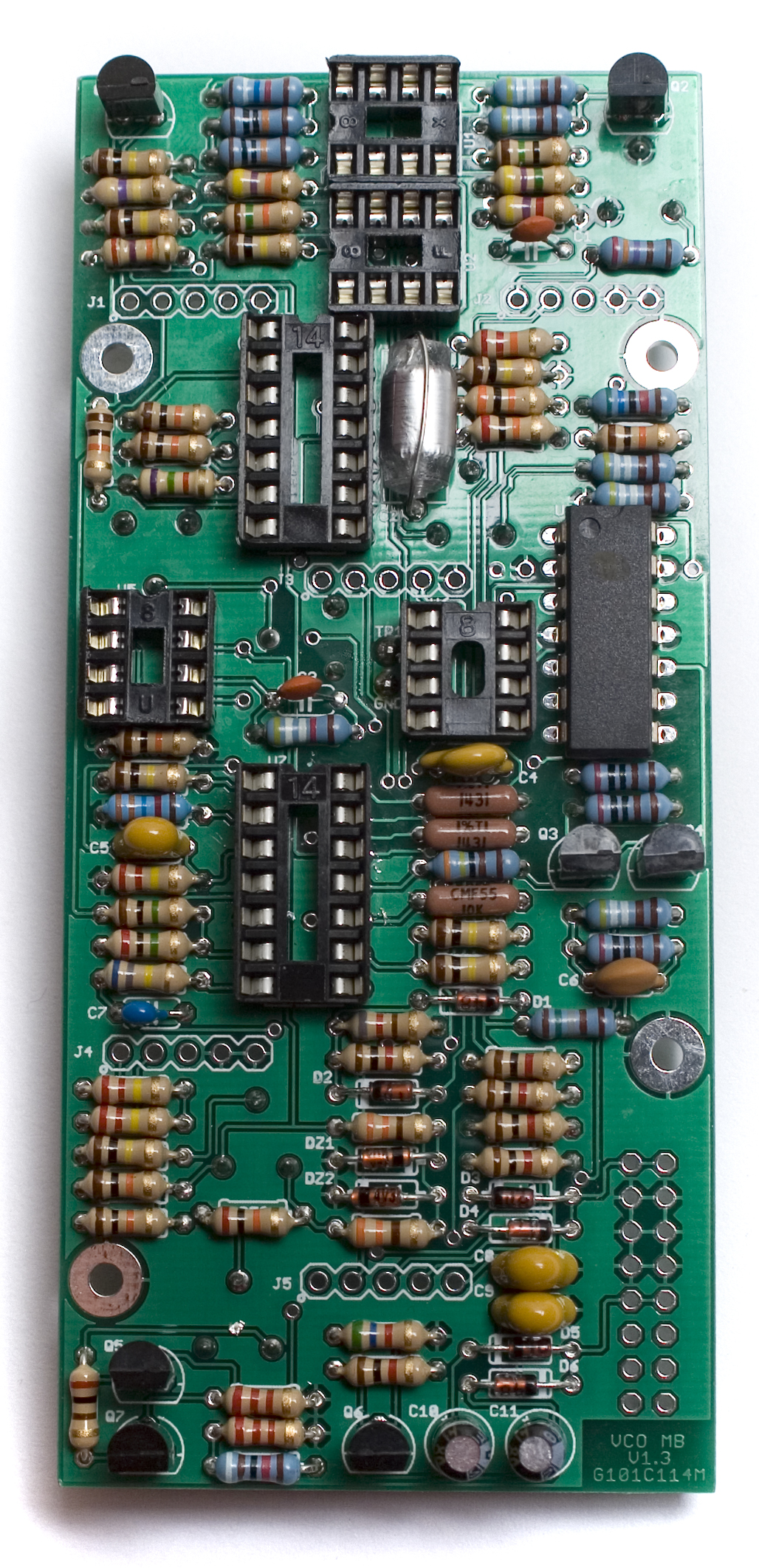
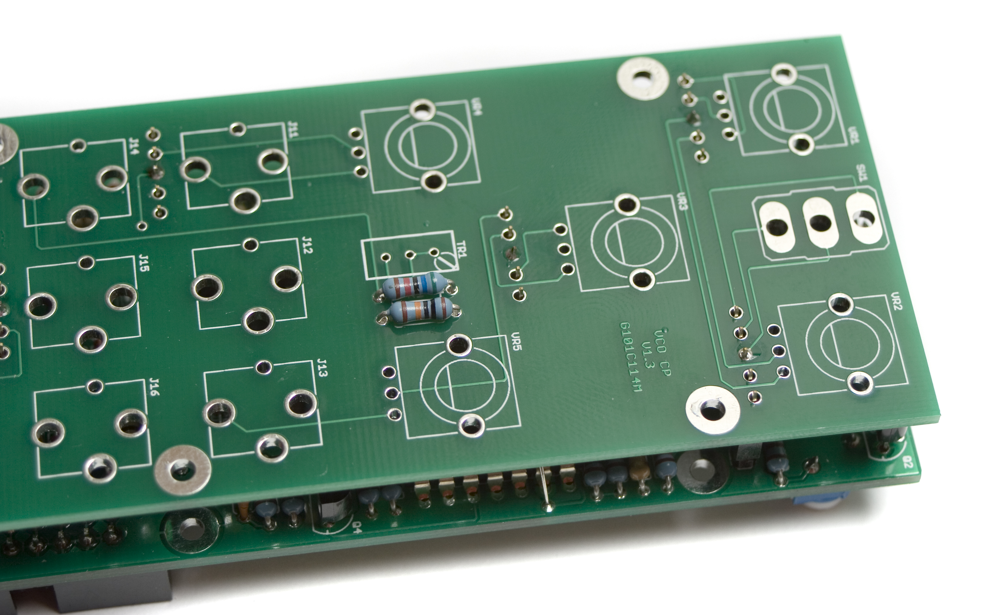
Resistors
It is recommended to split the resistors into two groups when populating them, so that it is easier to solder them all in place.
DO NOT Populate the Tempco Resistor yet (TC1). This resistor needs to be populated later in the build.
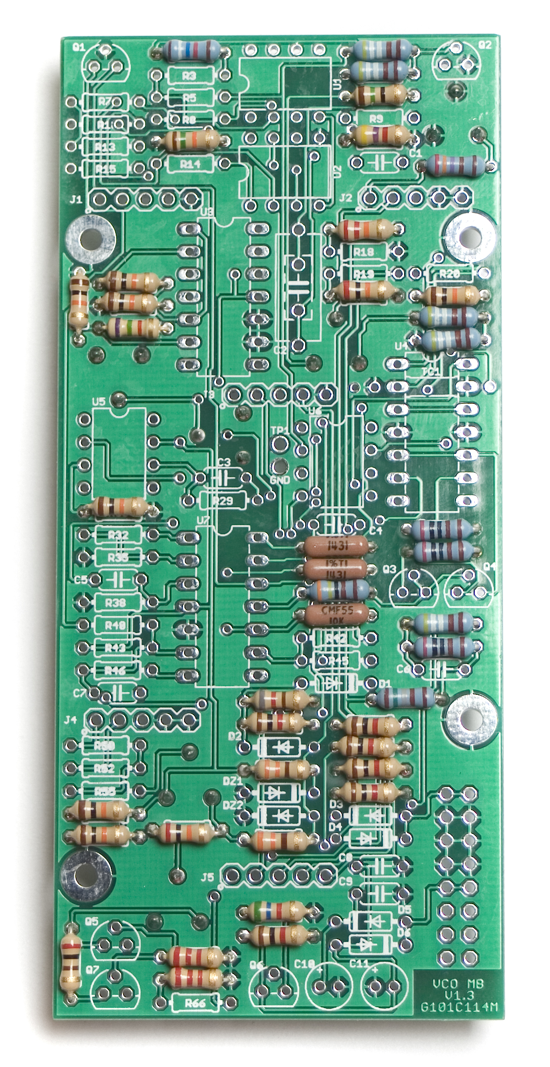
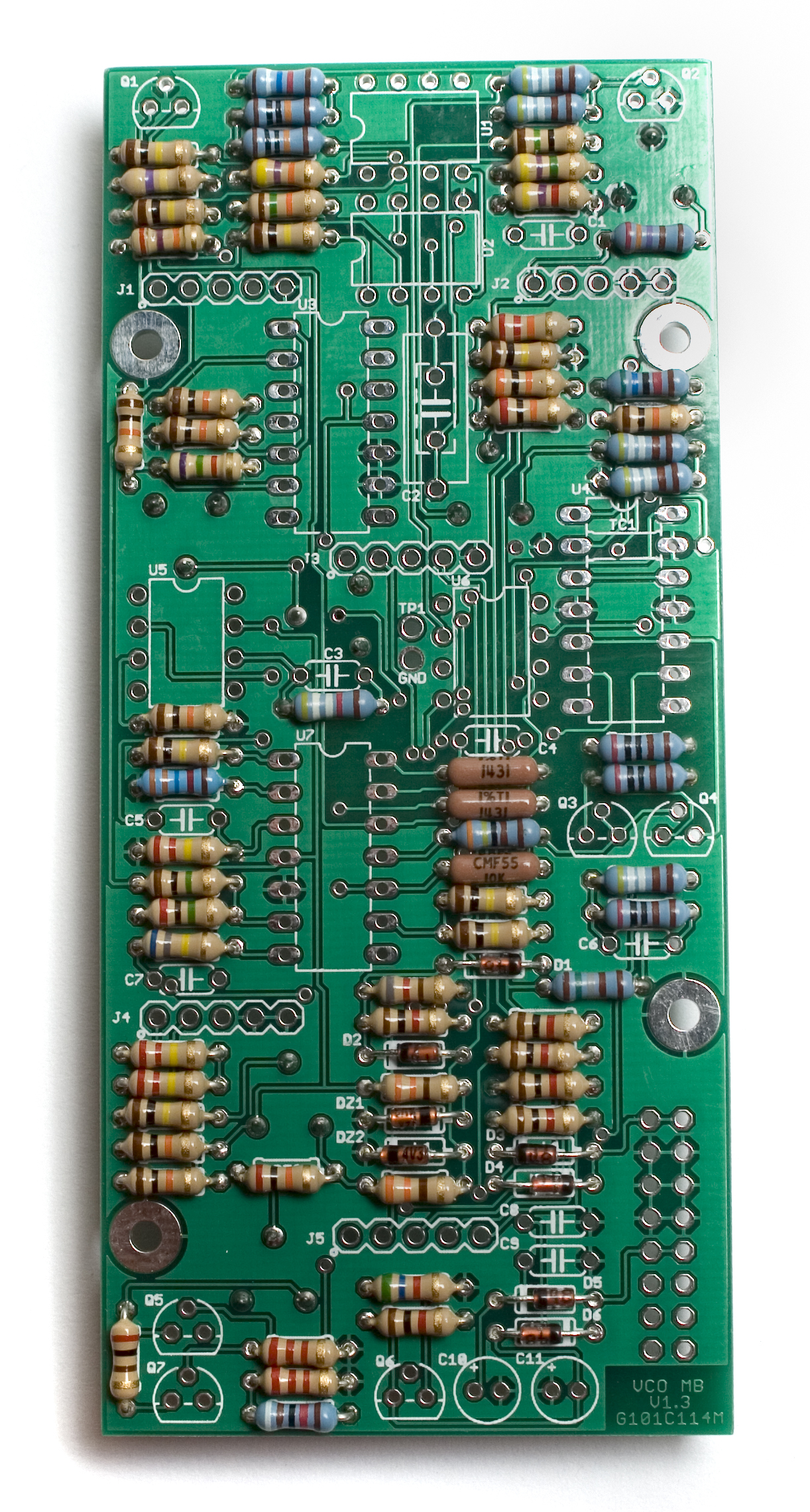
MST VCO Resistors group 1
Insert each resistor into its designated spot, as per the Bill of Materials.
After populating the first group of resistors, flip your board over, solder them and clip the leads.
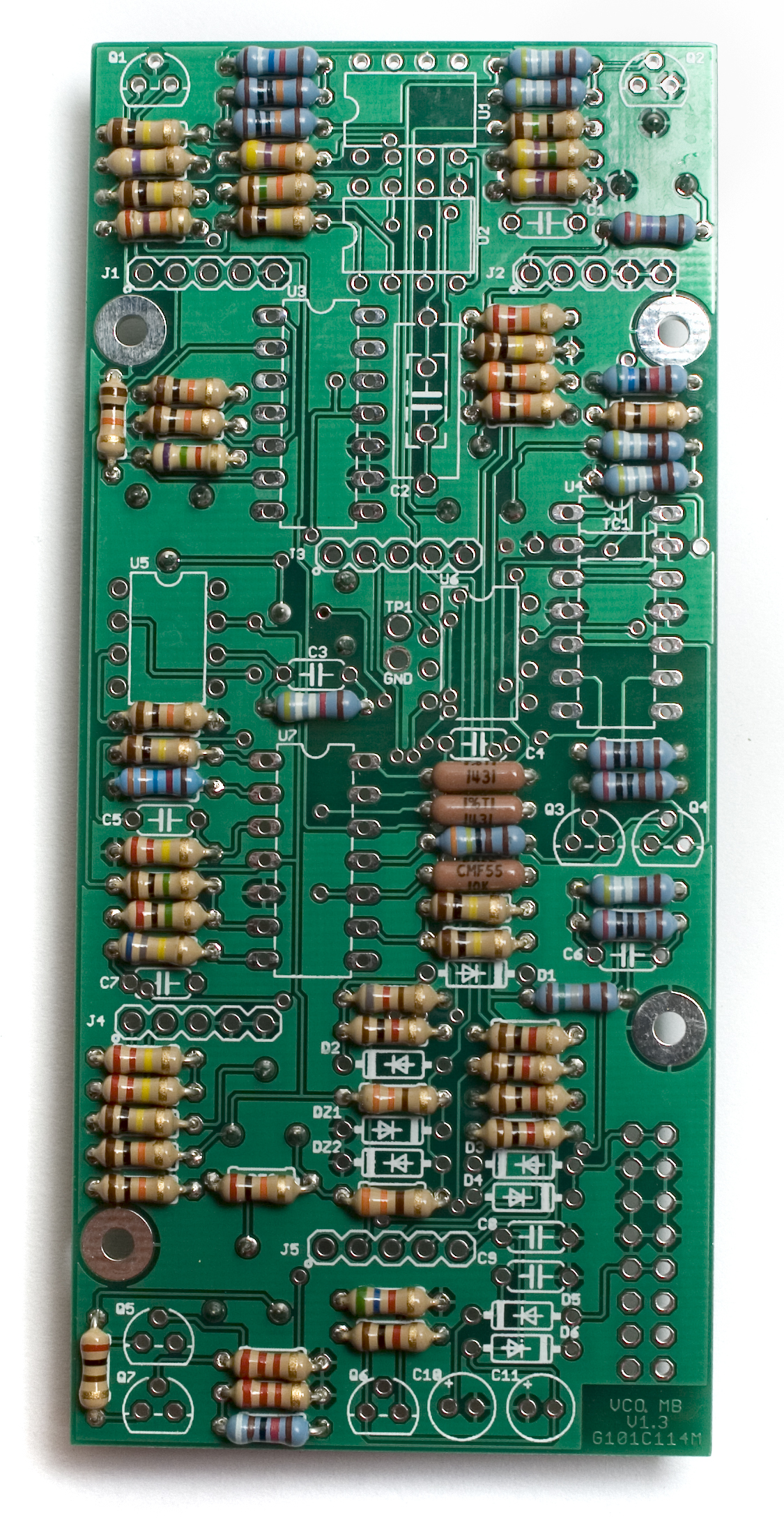
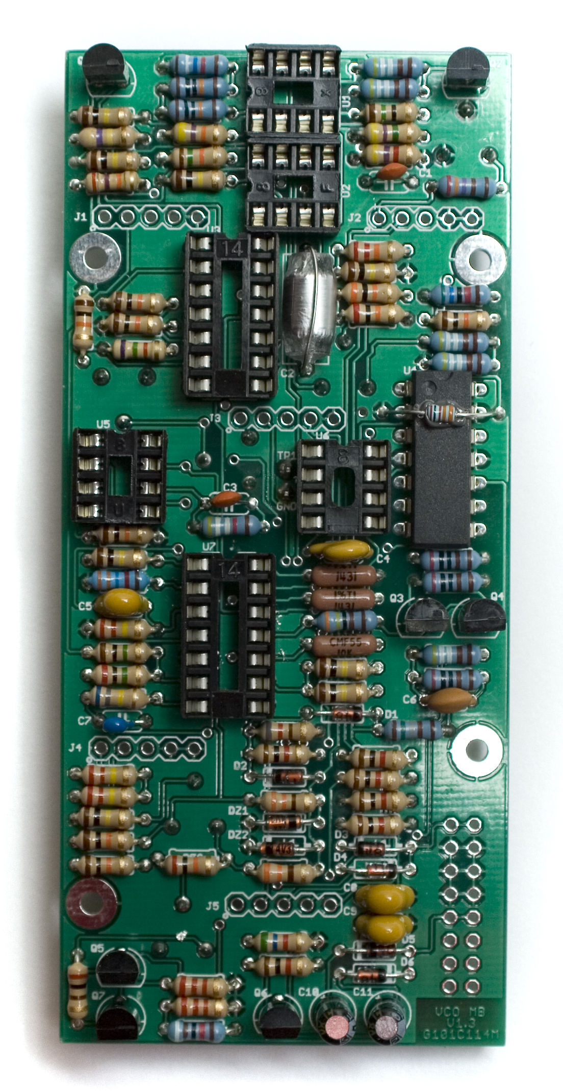
MST VCO Resistors group 2
Next up, do the same thing for the second group of resistors. Then flip, solder, and clip your leads.
On the BOM, you will notice there are a couple resistors that denote they are on the Control Panel. Go ahead and populate them as well.
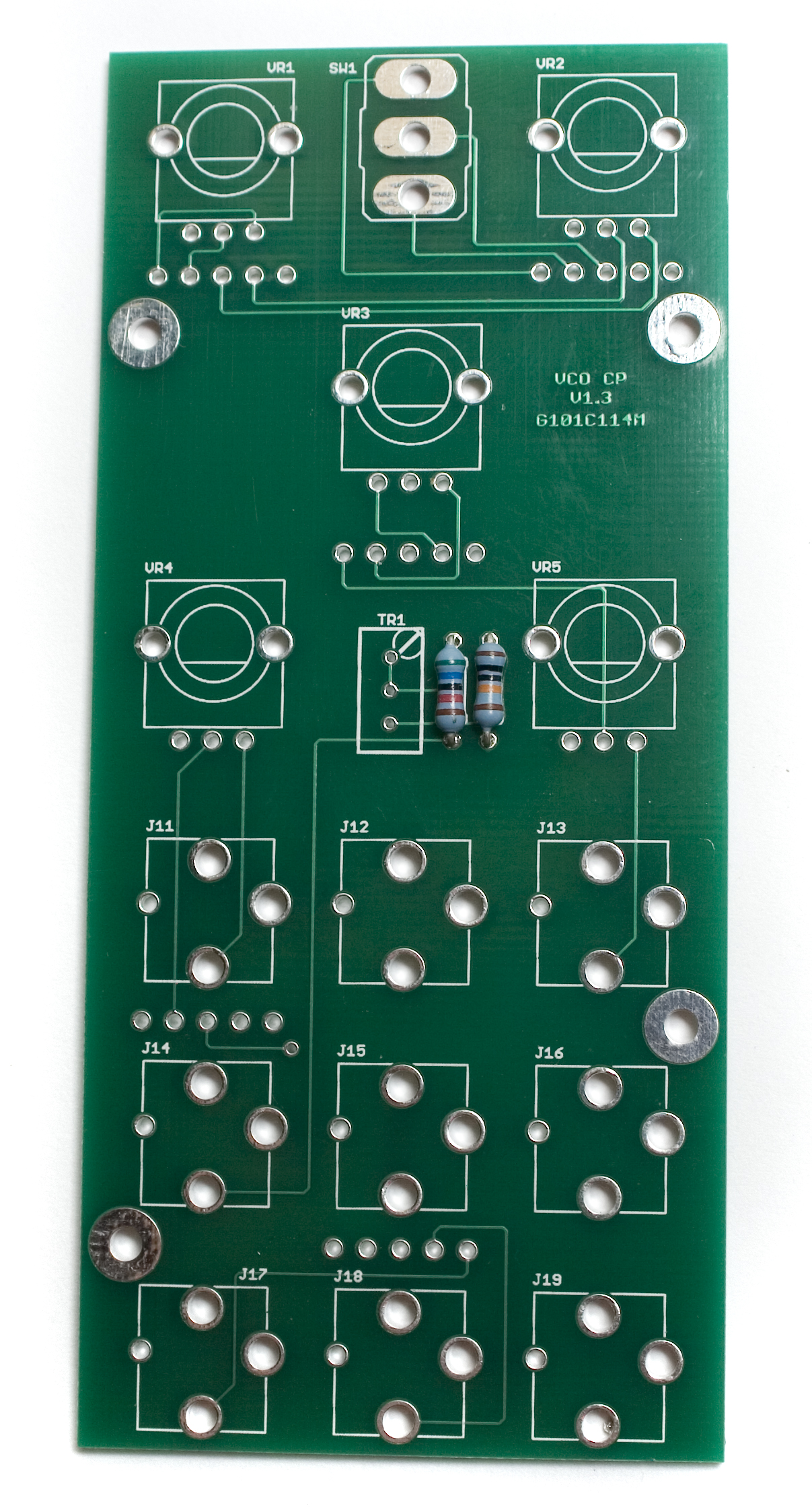
MST VCO Front Panel Resistors
Diodes
MST VCO Diodes
Next up are the Diodes. Diodes are polarized components, and must be installed with the proper orientation for them to function. When inserting them through the PCB, ensure that the black stripe on the diode matches the direction of the white stripe on the PCB’s silkscreen. Make sure to put the zener diodes (DZ1 and DZ2) in their proper places.
2 Pin Header
MST VCO 2 Pin Header
Now would be a good time to populate the 2 Pin Header on the back of the board. Simply insert the header into the holes marked TP1 and GND, then flip over and solder it in place, making sure it is straight.
IC Sockets
The MST VCO has one IC that does NOT use a socket. Do not populate a socket into the U4 position.
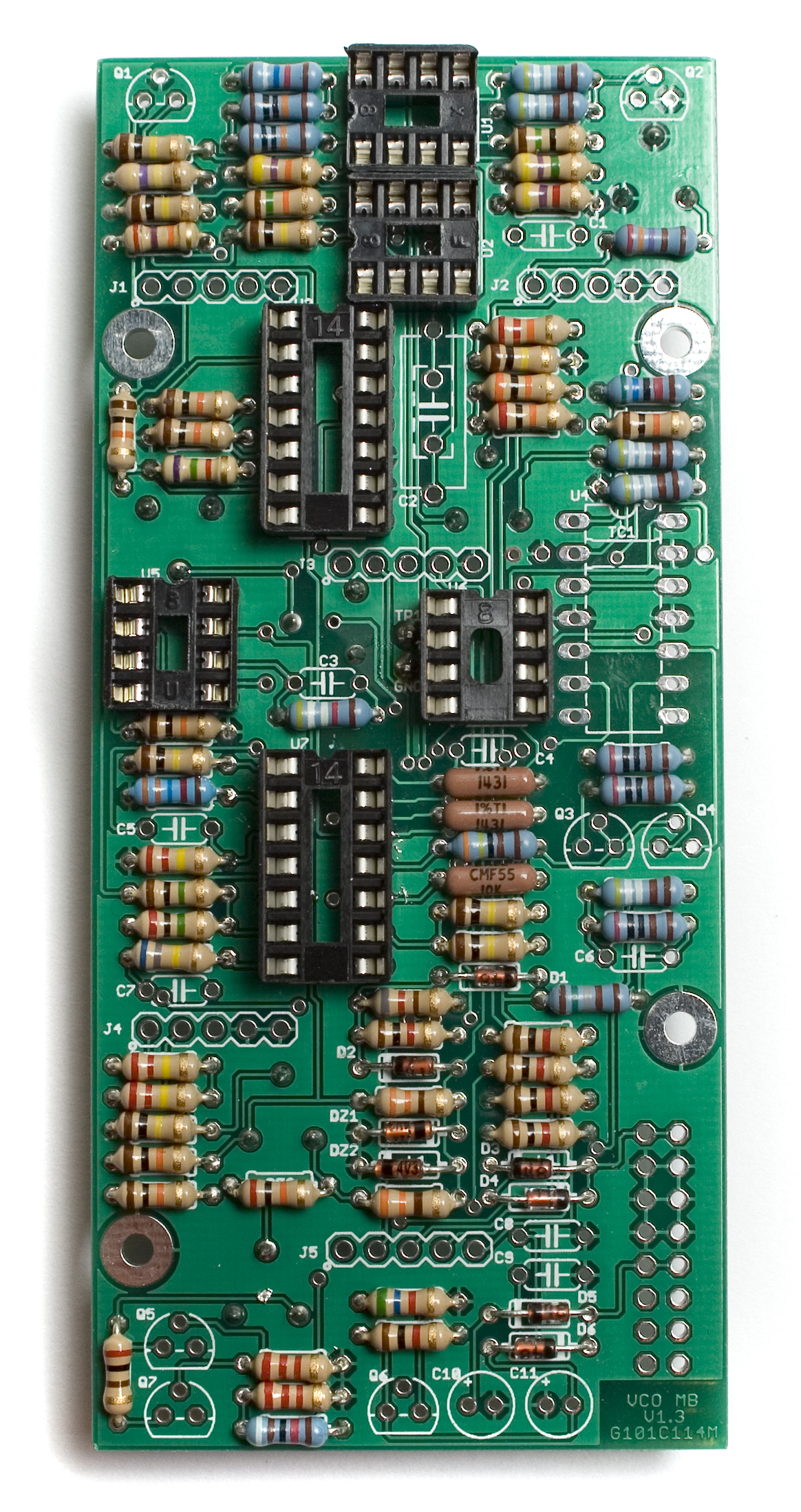
MST VCO IC Sockets
When inserting the IC sockets into their respective homes, pay attention to the alignment notch on one end of the socket. It’ll look like a little half circle that was taken out. Match this alignment notch up with the one on the silkscreen so that it is easier to align your ICs later, when the are populated.
Capacitors
MST VCO Capacitors
Now insert the capacitors into their respective spots, as per the BOM. With the ceramic capacitors, you may need to slightly bend the leads to get them to stay in when you go to solder them down.
The Electrolytic Capacitors are polarized components, and need to be installed properly. Align the longer lead (Anode) of the capacitor with the little + sign on the PCB. If they are improperly installed, it may damage the circuit, and could cause other components to fail.
Polystyrene Capacitor
Next up is the Polystyrene Capacitor. This component is VERY temperature sensative, and it is best to try to solder it without holding the iron on the leads for too long. You could even solder one leg, then let it cool, and solder the other leg.
First, we need to bend the leads so that it will fit into the PCB properly.
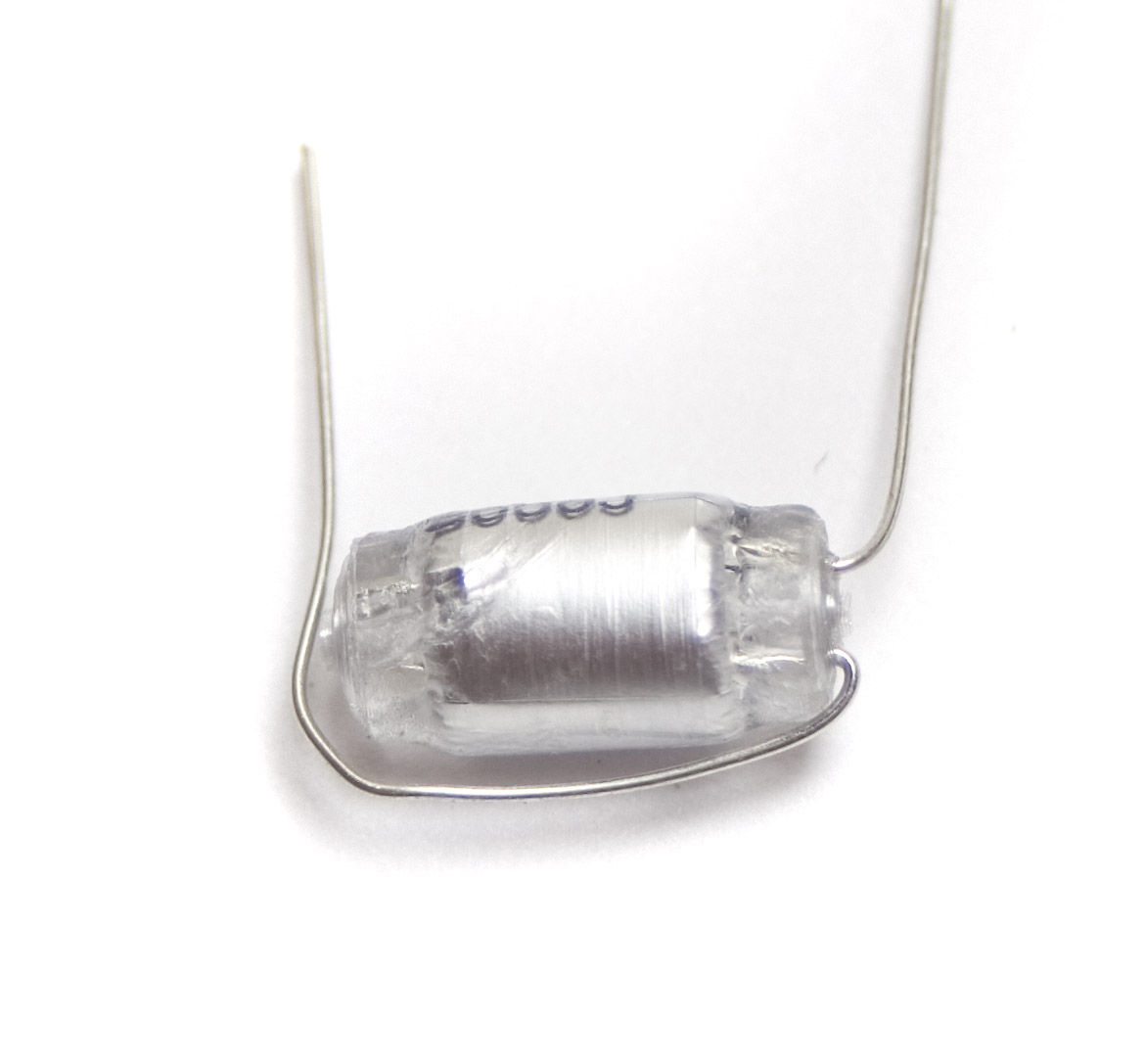
Polystyrene Capacitor
If you bend the leads of the Polystyrene capacitor like the picture shown above, it will be easier to populate, and ultimately easier to solder.
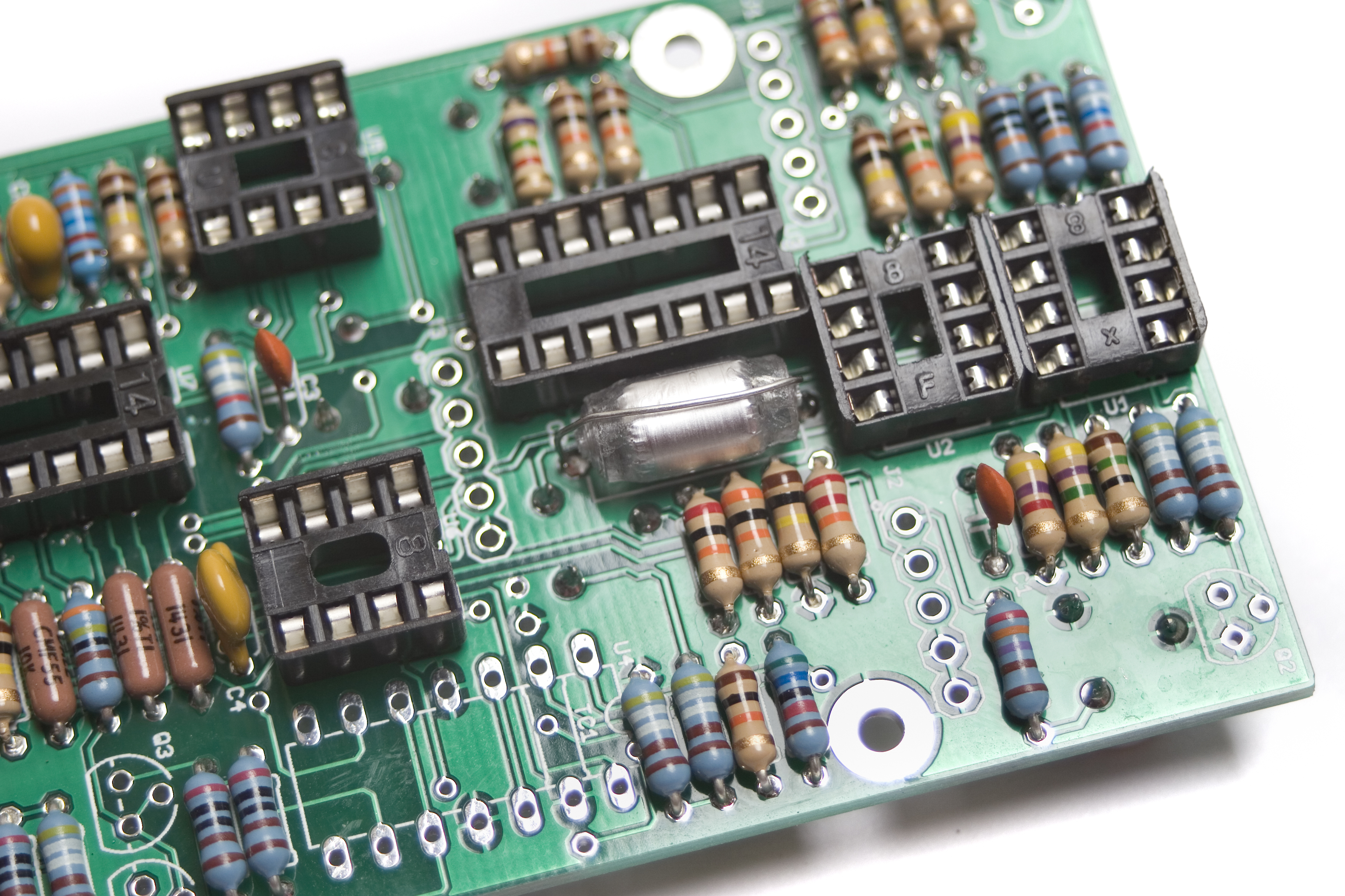
MST VCO Poly Cap Placement
This capacitor is non-polarized, so it doesn’t matter which way you place it into the PCB, but it is easiest to insert it into the farther apart set of solder pads.
Transistors
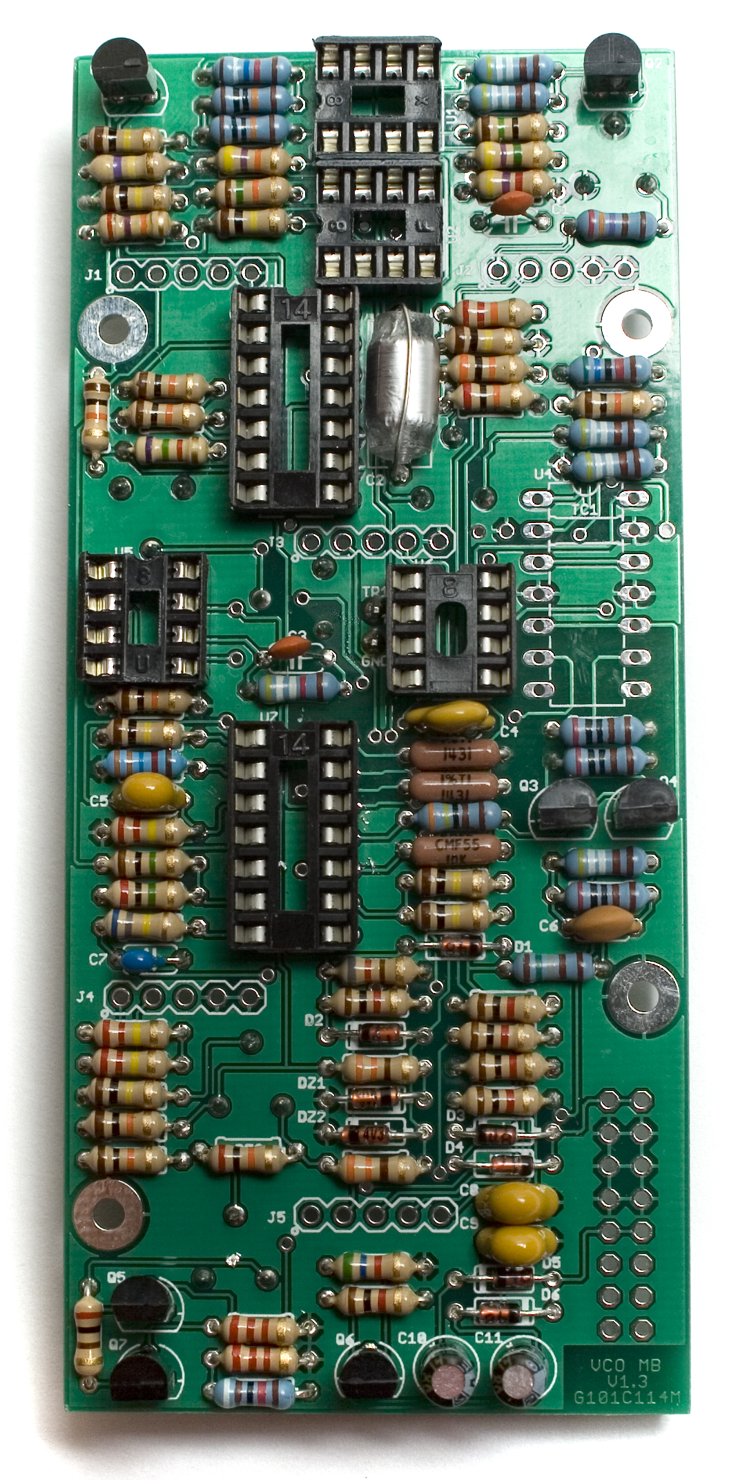
MST VCO Transistors
Next up are the transistors. Insert them into the PCB, aligning the flat side of each transistor with the flat side that is also on the silkscreen. Then flip your project over and solder, clipping any excess leads.
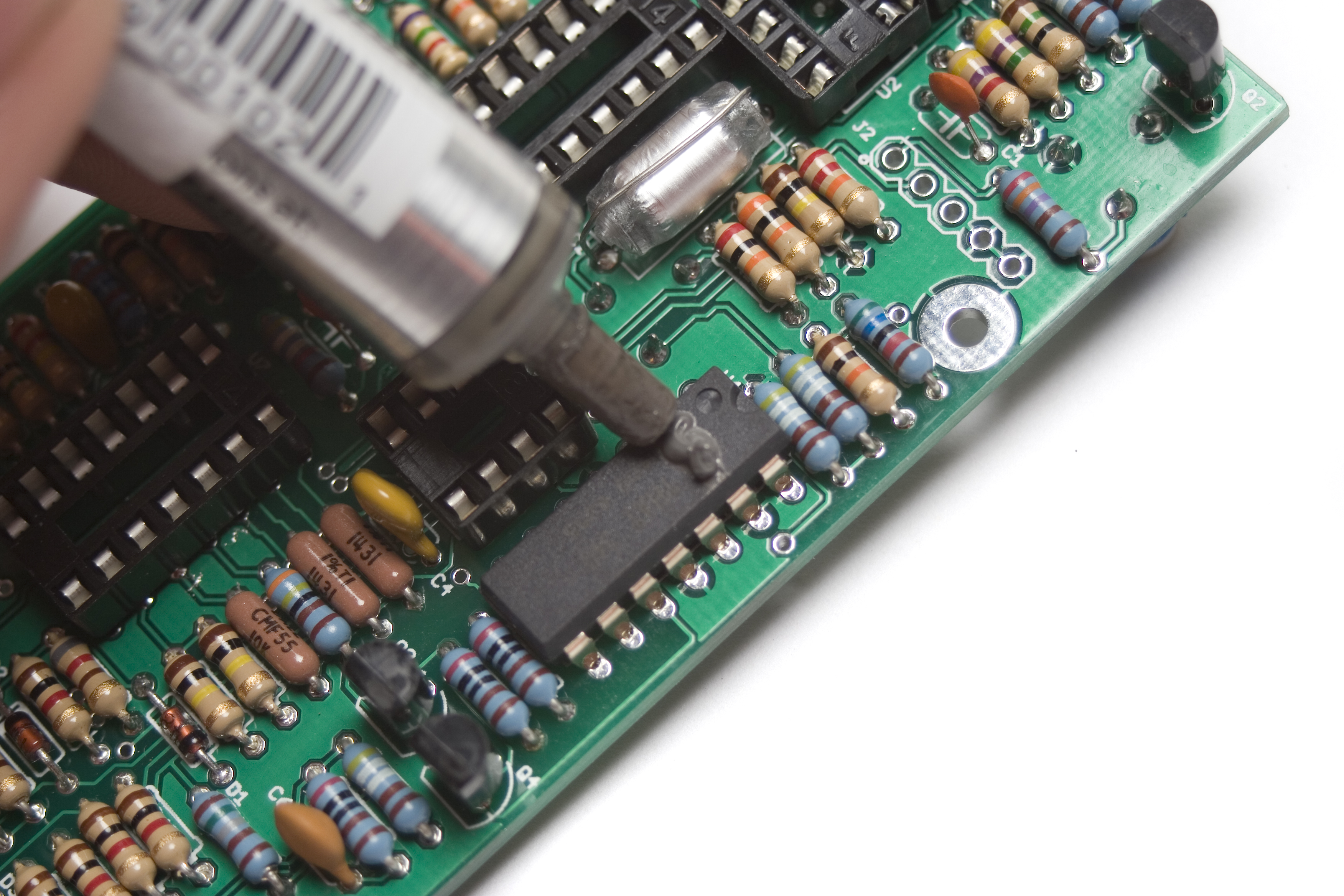
Transistor Array Chip
MST VCO that340p14
Insert the that340-P14 chip into U4, aligning the half circle notch on it with the same notch on the silkscreen. When it is snugly against the PCB, flip your board over and solder it into place.
Tempco Resistor
Before populating the tempco resistor, place a little dab of thermal paste onto the chip in U4 (that340P14). You can also use thermal tape (if you bought a kit from us, it’s the little blue square in a bag).
MST VCO Thermal Paste
Next, place the tempco resistor into the two solder pads that are just outside of pins 2 and 13 of chip U4. Make sure that the tempco resistor is sitting snug in the thermal paste or tape as shown below. Then flip your project over and solder it in place.
MST VCO Tempco
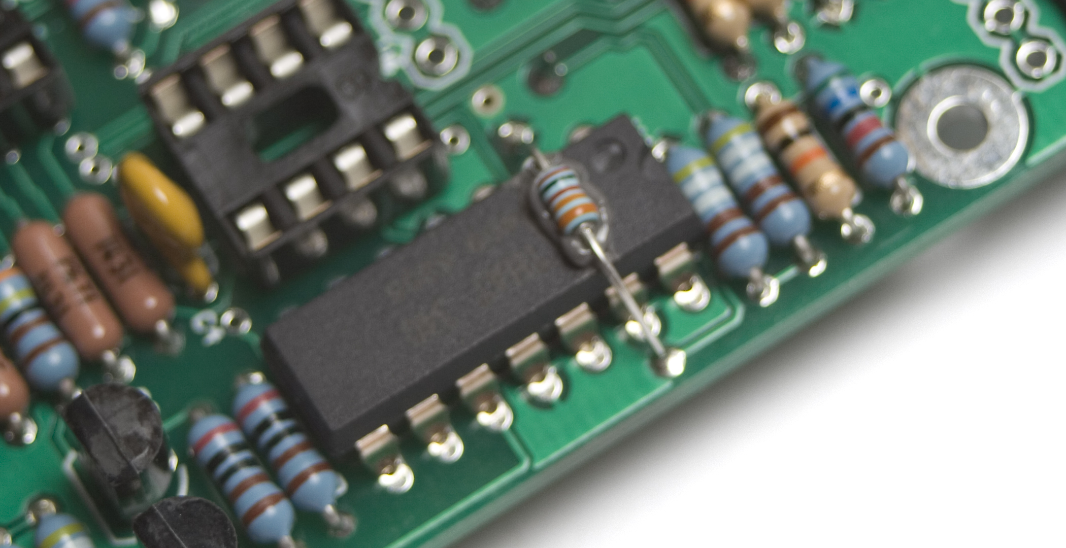
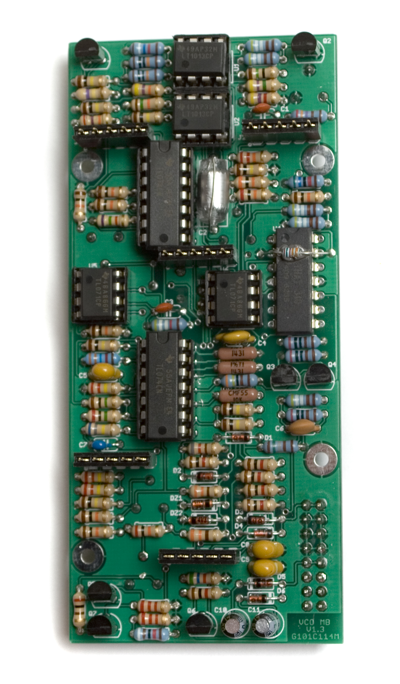
IC Placement
Next, insert the ICs into their respective sockets, making sure to align the notch in each IC with its socket, and the silkscreen below it as well.
MST VCO IC Placement
16 Pin Shrouded Box Header
Flip the board over, so that the trim pots are facing up now. Insert the 16 Pin header into the PCB, making sure to align the notch in the header with the notch marking on the silkscreen, as shown below. Then flip the board back over and solder it into place, making sure that is snug to the PCB.
MST VCO Power Header
5 Pin Board to Board Headers
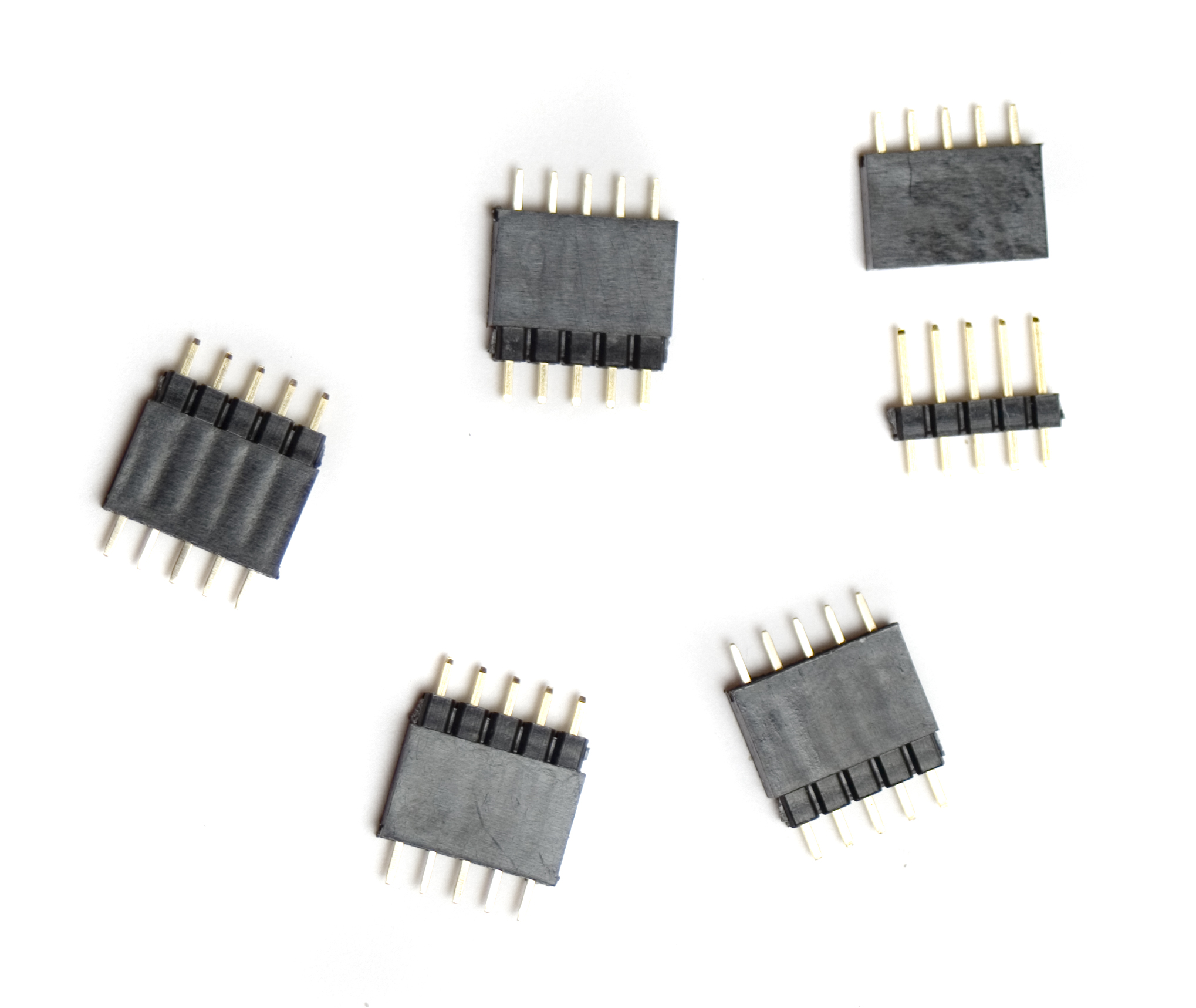
The easiest way to get the 5 pin headers and sockets into their spots, is to first assemble everything, and then solder them into place. First up, connect each header to a socket, with the longer part of the header going into the socket, like shown above.
Next, insert each header assembly into the main board, as shown below.
MST VCO Header Placement
Now you can place the control board over the top of it, aligning the solder pads for the sockets up, so that the pins of the sockets poke through the control board PCB.

MST VCO Control Board Placement
Next up, solder one pin of each header assembly on each side of the board, making sure that the boards are nice and flat, and everything is as straight as possible. If something gets a little crooked, or mis-aligned, just reheat the solder joint nearest the error, and straighten it out.
MST VCO Control Board Alignment
Once everything is straight, finish soldering all the headers and sockets into the PCBs. Carefully pull the boards back apart.
V/O Trimmer
MST VCO V/O Trimmer
Next up, insert the trimmer potentiometer into the designated place on the PCB, making sure to align the adjustment screw with the silkscreen representation of it. The side with the adjustment screw should be facing the top of the board, as shown above.
Now flip the board over, and solder it in place, clipping any excess leads. When soldering, make sure that the trim pot is fully flush with the board, or it won’t line up properly with the front panel.
Standoffs
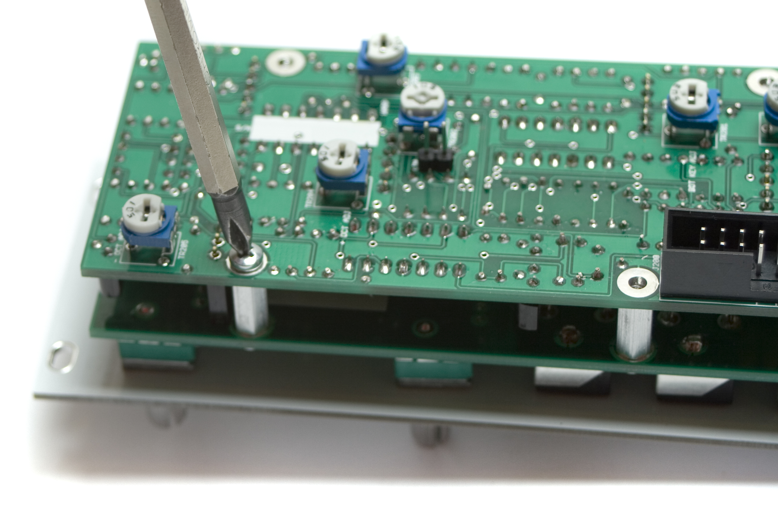
MST VCO Standoffs
Insert the screws for the standoffs through the PCB, and tighten them down to the standoffs, as shown above.
Jacks, Switches and Potentiometers
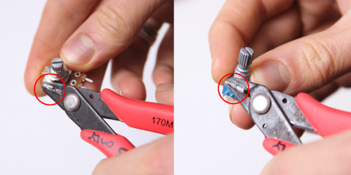
Don’t forget to cut the nubs on the potentiometers as necessary.
Now PLACE (do not solder yet!) the jacks, potentiometers, and switches in the PCB as shown below. Make sure to remove ALL the nuts and washers from your switches before panel placement.
Please read through the whole process before starting!
MST VCO Hardware
Now place the Front panel over the pots, jacks and switches.
Make sure that the 1V/O trimmer is aligned with the hole in the front panel during this part. If it is not, try to GENTLY align it with your fingers, or a tool. If it is off by a lot, it may be necessary to reheat the solder and adjust it while the solder is loose.
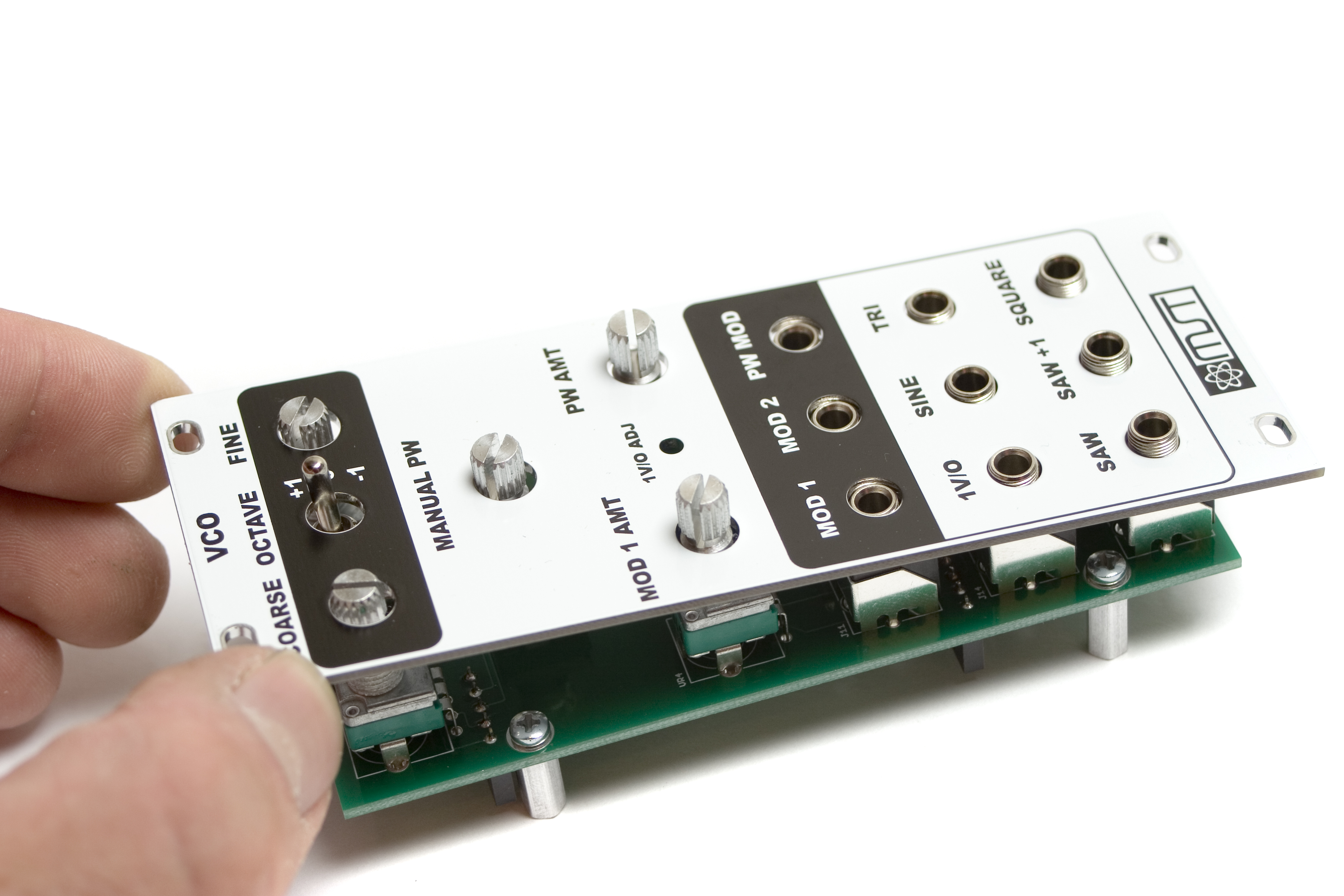
MST VCO Front Panel Placement
Use a tool to gently tighten the nuts and washers on the hardware. Be careful not to over-tighten the nuts.
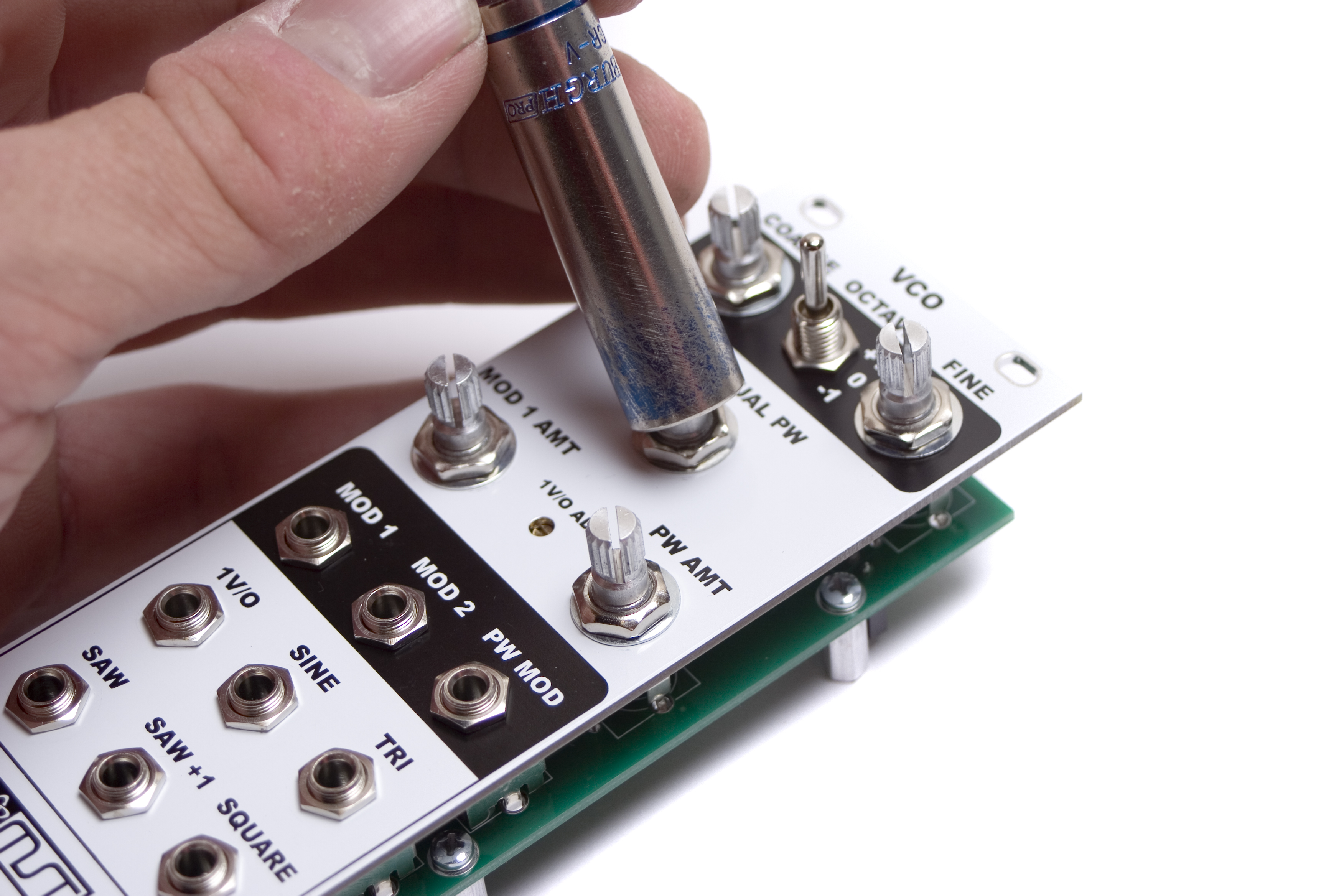
MST VCO Hardware tightening.
Now that your components are tightened, flip it over and solder the back side of the control board.
Final Assembly
Next, line up the two boards, so that the headers on the main board line up with the sockets on the control board. Gently push them together until the sockets and headers are fully seated.
MST VCO Final assembly
Flip the project over, and insert the final screws for the standoffs through the PCB, and tighten them down to the standoffs, as shown above. You can now install the knobs as well.
MST VCO Completed Unit
You should now have a completed MST VCO! Congratulations on the build!
If for some reason, you had troubles with your build, or it is not working right, you can check out the Troubleshooting Guide. It has loads of good information on some common pitfalls of building.
Next, check out our MST VCO Calibration Guide.
Interested
Thanks for the Interest, Jose, these instructions should be finished up within the next couple days
Build took about 2.5 hours.
Note that BOM shows the wrong color code for R6.. Should be Black, Green, Black (15 ohms) not Black Green Red as shown (that’s 1.5K)
Be extra careful when installing R2 and R35.. they are very close in value and right next to each other n the component strip yet one is a 1% 33.6K and the other is a 5% 33K
This is a compact/crowded PCB and it is easy to make solder bridges. be extra careful and inspect your work under a 10X loop and lots of light.
Another great kit from Syntrotek.
Hey Mike,
Thanks for the kind words.
We will make changes to visual BOM so that is has the correct color/value for R6.
It is definitely a more challenging build but highly satisfying!
-Zach
OK.. All done.. but no output. I have built many analog circuits before, but somehow, I had IC3 in backward and it shorted the power supply when I turned it on (stupid dots.. good on the 8 pins, wrong for the 14!).. anyhow, I replaced that IC and U7.. then I replaced the 2 FETs Q1 and Q2.. still nothing (well, I do get a very low signal odd saw wave that cannot be changed in pitch).. Do I need to replace U1,U2, U 5 and U6 as well? What about the THAT U4..
I don’t see any shorts or bad solder joints. Without a schematic, I am just down to randomly replacing parts.
Anyway, very annoyed that I did such a noob mistake. Grr.
OK.. fixed the issue.. Maybe this is a lesson for others..
The small diodes that “steer” the voltage from the header (D3- D6) cannot take a lot of current and one failed (D5 in my case).
You can test diodes with a good DVM (they often have a diode test setting).
All of the kits have a diode bridge between the power input and the board power. Not for reverse polarity protection so much as it is for just putting the board voltage at the correct polarity even if they did reverse the power input connector.
Unless someone puts an IC in backwards. Then, it shorts out, burns up and will usually take one of the rectifier diodes with it.
The advantage of using a small signal diode for this rather than those big muti-watt 4000 series rectifier diodes (that people use for rectifying AC power) is that they can only handle 300mW and double as a fuse before everything gets out of hand and takes out more than the IC.
Hey Mike,
Thats a total bummer about the IC being backwards. First thing I would check is the power diodes, they are the first thing to pop usually so that the other ICs are protected. If you still can’t figure it out, you can shoot us an email over at store@synthrotek.com, and we can work it out.
Best,
-Patrick at Synthrotek