Important Links
Product Page
Store Page
Assembly Instructions
Bill of Materials
Drill Template
Capacitor & Resistor Lookup Guide
Thank you for purchasing the Synthrotek TURN kit! This is a great beginner build. If you feel like you can handle it, please proceed! If not, get some help from a friend with experience or purchase a fully completed unit.
Please build according to the BOM, and not these instructions alone or the pictures alone.
RESISTORS
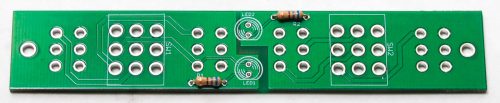
Populate the two resistors. Resistors are non polarized, so it doesn’t matter which direction you put them on the PCB. Once everything is in place, carefully flip your project over and solder the components in place. Clip any excess leads on the bottom of the board.
STANDOFFS
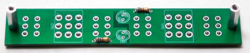
Add the two standoffs as shown above and attach them via the two supplied silver Phillips screws.
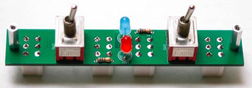
LEDs
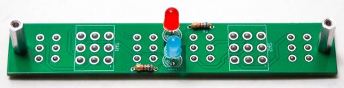
Insert the two LEDs as shown above by aligning the flat side of the LED with the flat side on the silkscreen graphic. You can take the panel and hold it over the main board and push up the LEDs so that they are off the PCB about 1/4″. LEDs are polarized, make sure to double-check your orientation before soldering.
MOLEX CONNECTOR
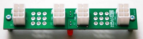
Populate Molex connectors as shown above by aligning the GND notch on the connector with the silkscreen graphic on the PCB. Carefully turn over to solder.
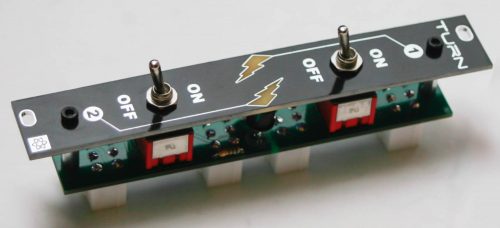
3PDT TOGGLE SWITCHES
Add the two 3PDT toggle switches to the PCB as show above. You can orient the switches either way (they will fit only two ways into the PCB), just make sure it looks like it does above. DO NOT SOLDER JUST YET.
LED BEZELS
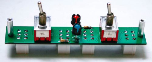
Add the two black LED bezels over the LEDs as shown above.
SWITCH NUTS
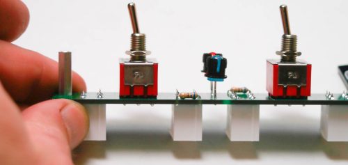
Add one switch nut to each switch as shown above. Screw/unscrew the nuts so that they are at the same height as the two 15mm standoffs.
PANEL ASSEMBLY
Take the panel and place it over the PCB as shown above. Make sure the graphics on the panel are oriented the same direction as the silk screen on the PCB. Now gently tighten down the remaining switch nuts and add the black hex head screws to hold the panel in place. Solder the switches in place.
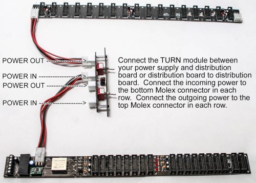
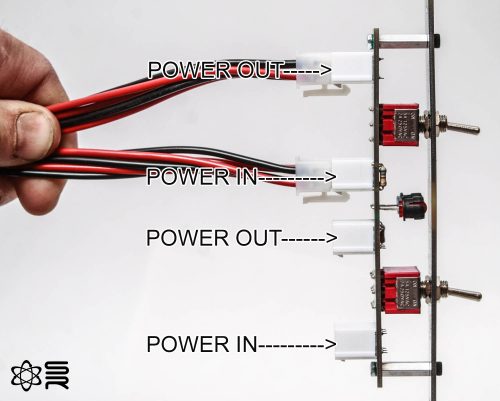
POWER CONNECTION
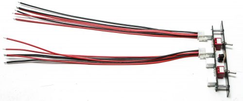
The Turn module offers 2 channels of manual power switching. Plug the Molex connection FROM your power supply or hot distribution board into the lower Molex connector in each channel. Outgoing power comes out the top Molex connector. See diagrams below.
You can still use the TURN module if you do not use Synthrotek brand power supplies or distribution boards. You can select Molex adapter cables (supplied by Synthrotek) to wire the TURN to your existing power supply. If you have male spade connectors you can solder directly or them or use female spade connectors and attach them to the Molex adapter cables. We have 3 ground wires (black) in our system of power supplies or distribution boards, but you if you have only one ground connection, just use one of the black cables. This will work great.