


Important Links
Product Page
Store Page
Assembly Instructions
Bill of Materials
Capacitor and Resistor Lookup Guide
5A Eurorack Power Supply and Panel Power Entry Assembly Instructions
!!PLEASE MAKE SURE YOU FOLLOW THESE INSTRUCTIONS WELL AS ERRORS CAN RESULT IN A DAMAGED POWER SUPPLY OR MODULES!!
Noting could be more exciting than finally getting a great power supply into your rig and these instructions are here to help you assemble this simple kit asap. Below you will see a photo of the 3U Panel with Panel Controller PCB, 3U Panel, and Main Power Supply PCB. Below that is the same, but in 1U @ 6HP.
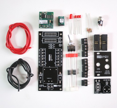
Eurorack Power Supply 1U Kit
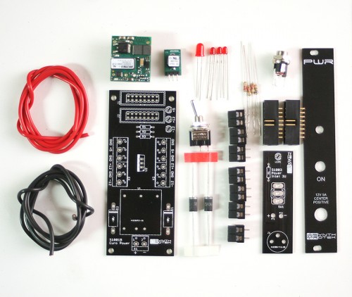
Eurorack Power Supply 3U Kit
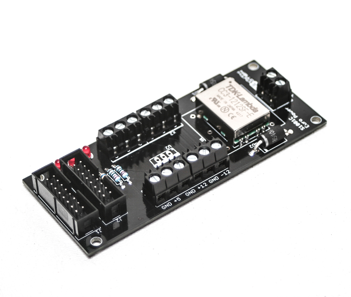
If selected, your kit will include a TDK 250mA 12v regulator in place of the 1.3A Murata regulator shown above:
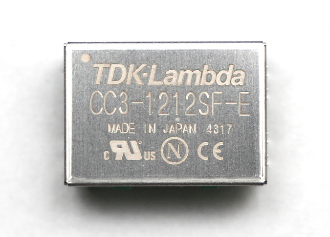
TDK 250mA 12V Regulator
Assembly
Attention: Changes may occur after the Assembly Instructions are created and the photos may not reflect those changes. Always use the BOM to verify the placement of components.
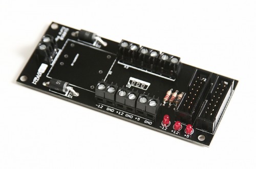
After you determine which kit you bought, check to make sure you have all of your parts, then grab the main power PCB and populate the PCB as shown below. Start with Resistors, 3mm LED’s (the FLAT side of the Silk Screen on the LED area indicates the NEGATIVE or CATHODE or SHORTER lead of the LED), Diodes and Power Cable Connectors.
 After that, add the 16-Pin Keyed Connectors, make sure you orient them as below. The KEY on the Shrouded Header will correspond with some small notches on the Silk Screen. Solder each pin from the backside of the board very carefully as to not accidentally connect two or more pins together with too much solder.
Next, Add the two power IC’s. The larger will only fit in one way, the Smaller COULD be inserted backwards; follow the orientation below.
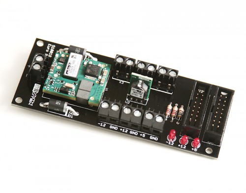
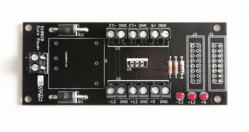
Fantasic, pretty simple, huh? Check your work against the photo below to ensure proper orientation of components.
You are now ready to start assembling your respective panel.
Eurorack Power Supply Assembly Instructions
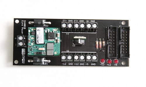
TDK 250mA users: use the photo below for reference orientation. The 5V converter (U2, not shown) is optional and orientation is identical to the standard 1.5A version if installed.
Please follow the instructions below for how to assemble your 1U or 3U Power Entry Panel. Both the 1U and 3U have very similar instruction.
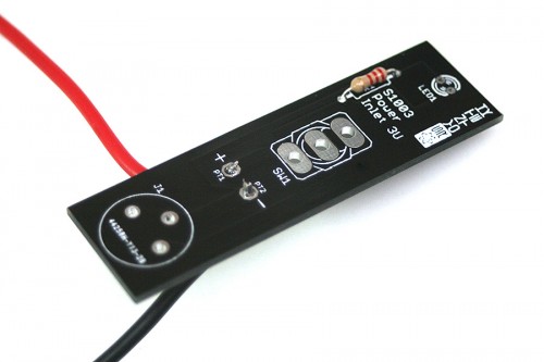
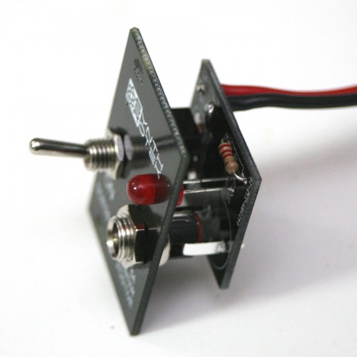
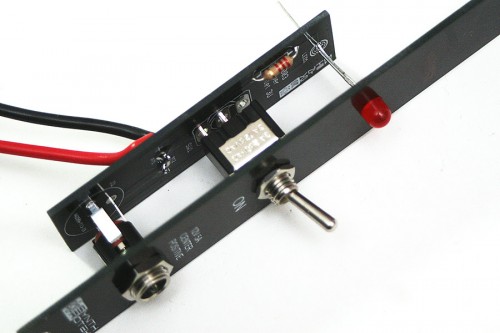
1. Seat 2.2K resistor onto the PCB and solder into place.

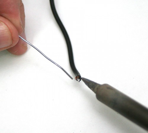
2. Strip a small a short amount of BOTH the RED and BLACK wire AFTER you have cut the wire to your desired length and then tin both ends with a small amount of solder.
Kit Comes with 2 FEET of each Red and Black wire. If you need more, you can purchase some in our store, or find any 16 gauge AWG type wire.
3. Run the red wire trough the back of the PCB going in through the + (positive) side on the front. Run the black wire through the back of the PCB going in through the – (negative) side on the front. Solder both wires into place and trim excess wire that pokes through the front.
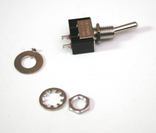
4. Take the top nut, locked washer, and keyed washer off of the SPST or SPDT (either will work) switch. You will not use the locked washer or keyed washer, so you can put those aside. Run the bottom nut up one thread so it sits barely off the bottom. Next, take the switch and mount it to the Panel and screw down the nut finder tight.
5. Take the top nut and washer off the DC jack, and seat into the front PANEL. You will not need the washer, so toss that aside as well. Then mount the washer into it’s panel hole and tighten the nut down finger tight.
6. Take the LED and sit the shortest leg through the LED hole that’s closest to the flat part of the LED circle on the PCB.
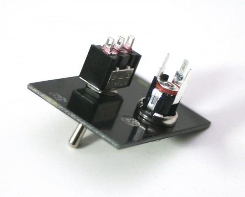
DON NOT SOLDER THE DC-JACK, LED, OR SWITCH to the PCB board YET. First align all of your components together to make sure a nice level fit. THEN solder the LED in place after you have make sure that the 5mm LED has slide into and has stopped fully into the Front Panel. Once you have a good fit of the other components, solder those as well.
Clip your excess wire and leads, tighten your nuts (not too hard) and you are ready to wire this up to your Main Power Supply Module.
Connect your color coded wires to their respective input connectors on the Main Power PCB and screw them down tightly.
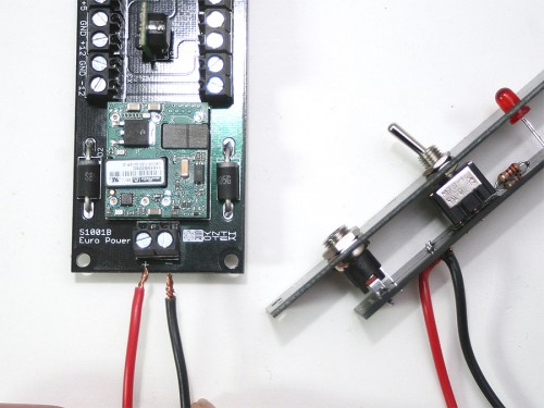
Connecting the Panel wires
You are now ready to plug in the 12V 5A Power Adapter into the front panel. Check to see if your panel LED illuminates and that the 3 LED’s on the Main Power PCB illuminate as well.
You can now connect your Power Distro PCB’s or Flying BUS Cables, now add your modules and make some noise!
Just in case this is useful to others… Consider this a “mini review”.
Design: The front-panel PCB is “attached” to the panel via solder points on the jack and switch. It’s a very lightweight and functional design. Not much else to say about the design of a power supply panel, but this one follows the standard convention of the input jack at the bottom, the switch above that, and the LED at the top. (As it should.)
Quality: I found the parts to be very precisely manufactured and everything was a perfect fit. The front panel feels as if it is made out of the same material as the PCB.
Time Required: For me, this Eurorack Power Supply kit required roughly 3 hours for complete assembly, from unpacking and checking the BOM to complete functional power supply. I would say the minimum would be around 2 hours for someone that is really good with soldering on such a small PCB.
I relied on a large lighted magnifier quite a bit to be able to see what I was soldering, (my vision just not what it used to be!) and my large hands didn’t help any… I resorted to using a number of alligator clips, mini-vise (handy-helper), and other gadgets to aid in getting components soldered.
The large IC (voltage regulator) has fairly large leads (look slightly copper colored not the normal tin look), and they took quite a bit of time/heat to get solder flow nicely. For 6 leads I spent about 25 minutes guaranteeing I had nice solder joints. You may do better!
Function: LED’s lit. Haven’t powered up a module yet. 🙂
Thanks David for the helpful comments man!
I just bought this kit. I assembled it exactly as instructed, i double checked everything, all my solder points are good. when i power it up, only the +12 LED lights up. I rechecked 3 times, all components are correct orientation, i have advanced soldering skills. still no luck.
is there a possibility a pcb could be bad?
any ideas?
thanks guys, love your stuff.
Hi Jared, it’s a pretty low possibility the PCB is bad unless you see a big scratch in it or a via missing. What kind of power brick are you using?
Skim through our troubleshooting guide, see if anything here helps: http://www.synthrotek.com/tech/troubleshooting-your-build/
Let us know how this goes.
@Steve Harmon
I checked that, sidn’t really see what i needed. the power brick is the one I ordered with the kit.
@Jared Scott
got it figured out, sorry for the alarm lol
works great, thanks a ton guys
@Jared Scott
I’m having the same issue, I’m only getting +12, what was it you fixed Jared? I’ve checked all the soldering and connection. Any help you can give?
While my build went fine and I didn’t get the ‘only the +12V LED lighting up’ problem, based on building this I can take a guess on what the issue was. Maybe this will help out future builders.
You have to pay close attention to the three LED placements. Two of them are placed with the polarity one way when referenced to board direction, the other one is placed the opposite way. The way the board was printed it can be a little tricky to make out that difference and in all honesty, I wondered if it was a printing error at first. Then, thinking the circuit through I realized why they did it this way.
Hope this helps. It is a great little power supply.
Rad, thanks for addition!
Hey so I’ve assemble the Main Power Supply but I’ve misplaced the outside panel with the switch (possibly while moving house). I do however have a 12v 5A power brick and two flat back bus boards. Is there a way for me to still power my rack? Can anybody help?
Hey there,
Since the front panel is really just there for the switch and power LED, you could definitely just wire a DC jack of same specs as what came with the kit (502-PC722A is the mouser # provided on the BOM in the build guide). Many folks drill a hole for mounting that jack, and if you’re feeling particularly ambition; you can add a switch (many tutorials and pages on youtube/DIY forums)
Is the 12v 5A brick from us? If not, you’ll want to make sure it matches the specs on the 5A Power Supply System page which says:
– Power connector must have a 5.5mm sleeve and a 2.5mm interior barrel pin
– Power supply must be 12VDC, 5A and have a center positive pin
I hope this helps and you get wiggling soon,
Michael