


Welcome to the assembly instructions for the Eurorack and Fractional Rack version of the Atari Punk Console. This synth is designed to go into either a EuroRack or a Fractional Rack. This is an easy build and great for those starting out on building their own kits. Lets get started!
BOM Layout
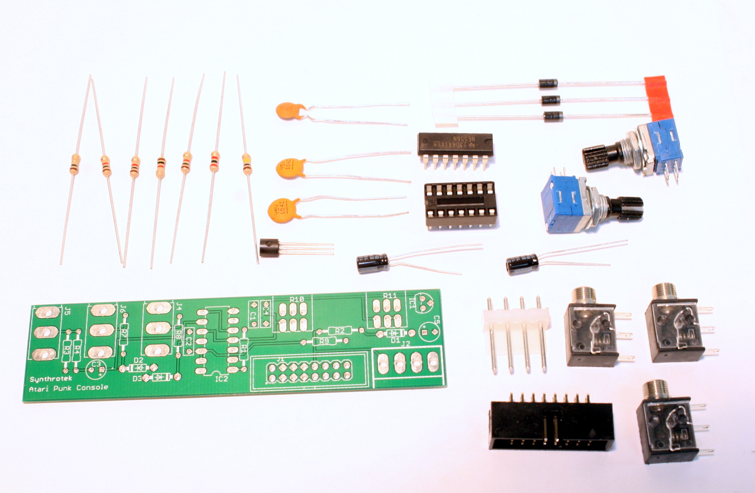
Eurorack and Fractional Rack Atari Punk Console Parts
If you’ve received your parts and ready to build, the first thing you should do is to check to make sure you have all the parts. Check your kit against the Eurorack and Fractional Rack APC BOM. If you’re missing anything we’ll send it to you free of charge.
Soldering the Components
Attention: Changes may occur after the Assembly Instructions are created and the photos may not reflect those changes. Always use the BOM to verify the placement of components.
Resistors and Diodes
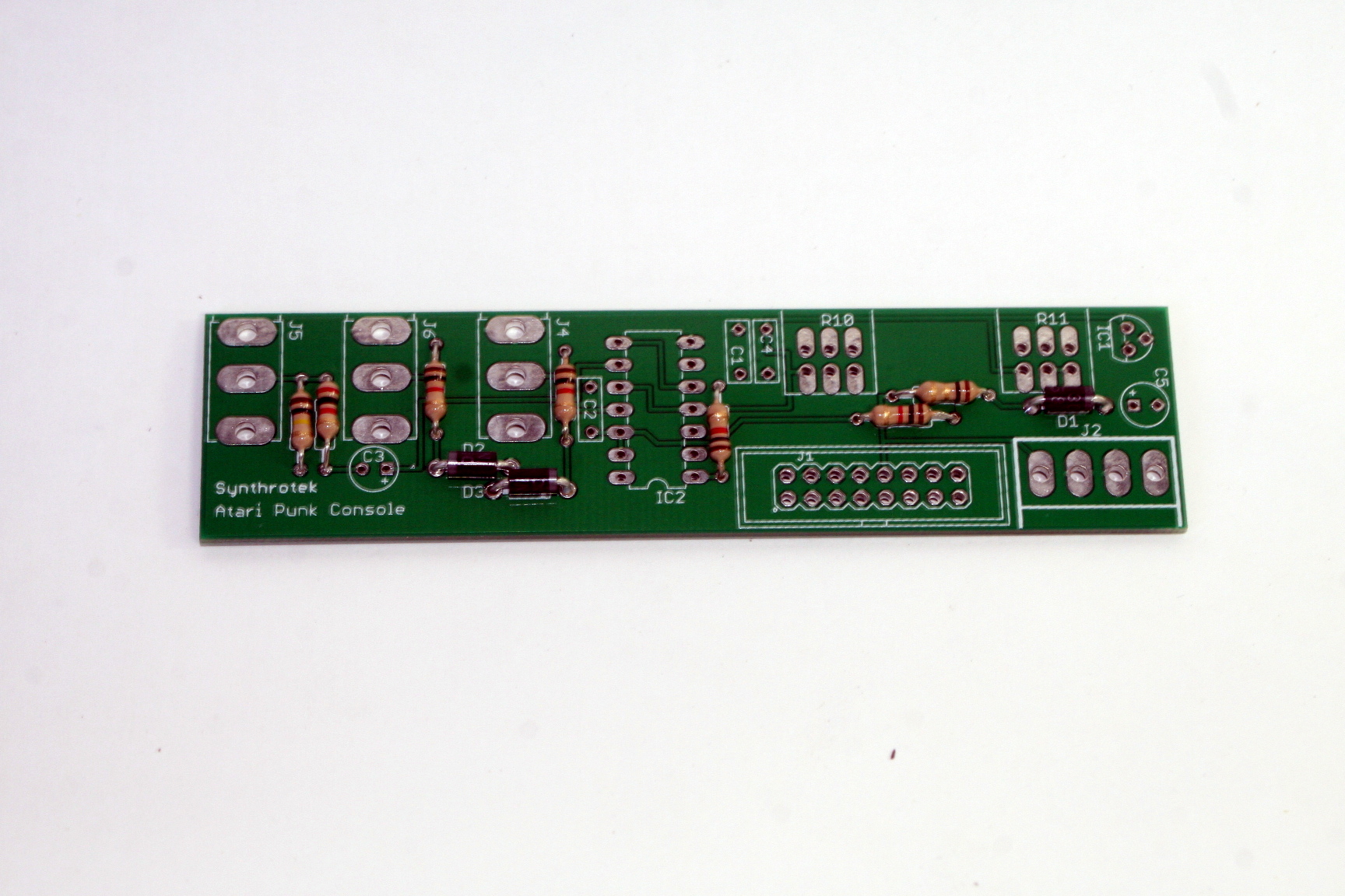
Eurorack and Fractional Rack Atari Punk Console Assembly Step 1
First solder all the resistors and diodes into place. Ensure that the line on the diode matches with the line on the PCB silkscreen. Resistors are not polar sensitive so you may install them in any orientation.
Capacitors
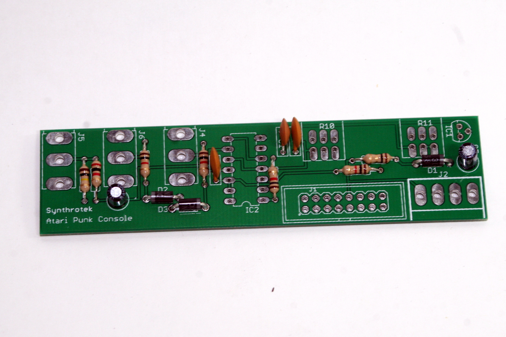
Eurorack and Fractional Rack Atari Punk Console Assembly Step 2
Now solder all the capacitors. The electrolytic capacitors C3 and C5 are polar sensitive. Make sure that the longest lead from the electrolytic capacitor goes into the hole marked with the plus (+) sign. The ceramic capacitors are not polar sensitive and can be installed in any orientation.
IC Socket and Voltage Regulator
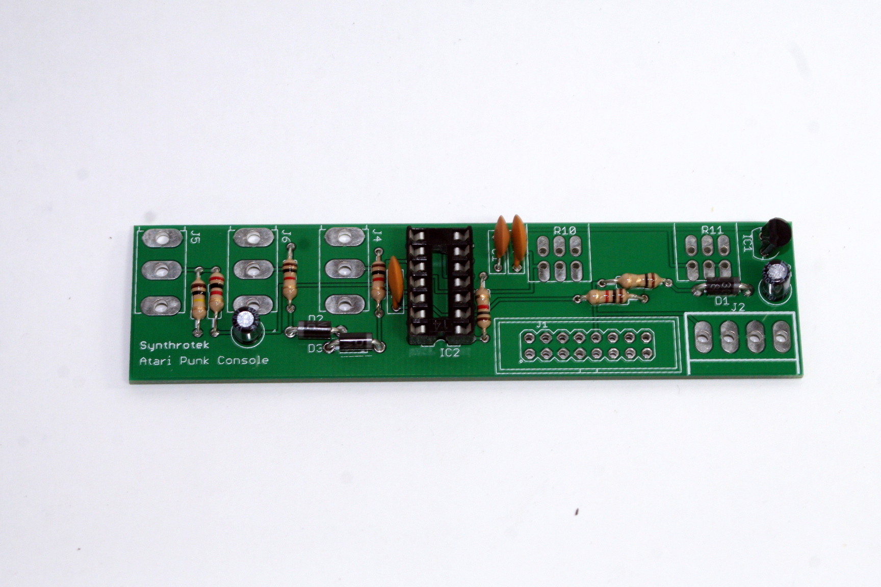
Eurorack and Fractional Rack Atari Punk Console Assembly Step 3
Now let’s install the voltage regulator and the IC socket. You need to align the flat side of the voltage regulator to the image of the flat side on the PCB silkscreen. For the IC socket, make sure that the notch on the socket matches with the notch in the image on the PCB silkscreen. A tip for soldering the IC socket flat to the PCB, first solder two opposite corners of the socket and then make sure that you get the socket flush to the PCB. Afterwards solder the rest of the pins and touch-up the two first pins as necessary.
Potentiometer and Jacks
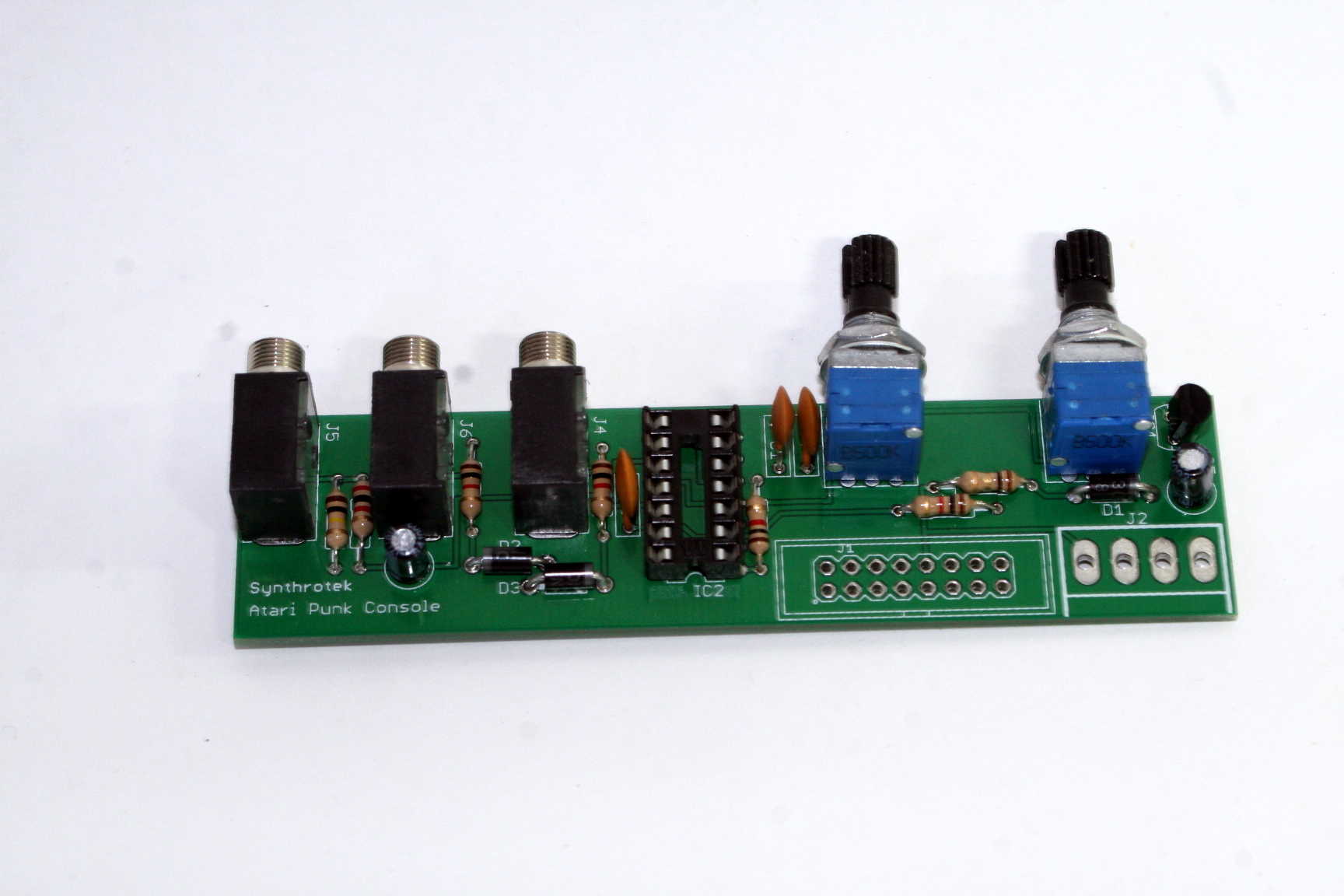
Eurorack and Fractional Rack Atari Punk Console Assembly Step 4
Now you can install the audio jacks and the potentiometer. If your pots only have 3 pins, install them in the three holes closest to the edge of the PCB. (The other three pins are not connected to the circuit; they are there for convenience for customers who purchase 6-pin pots.)
You can use a similar trick as with the IC socket to make sure that the component is flush to the PCB, just solder a single center-pin or two pins on opposite sides first and make sure that the component gets flush to the PCB, and then solder the rest of the pins.
When installing the pot, some pots come with nubs near the shaft that may get in the way of installing the circuit into a case. Check for a nub and clip as necessary.

Don’t forget to cut the nubs on the potentiometers as neccesary.
Pin Connectors
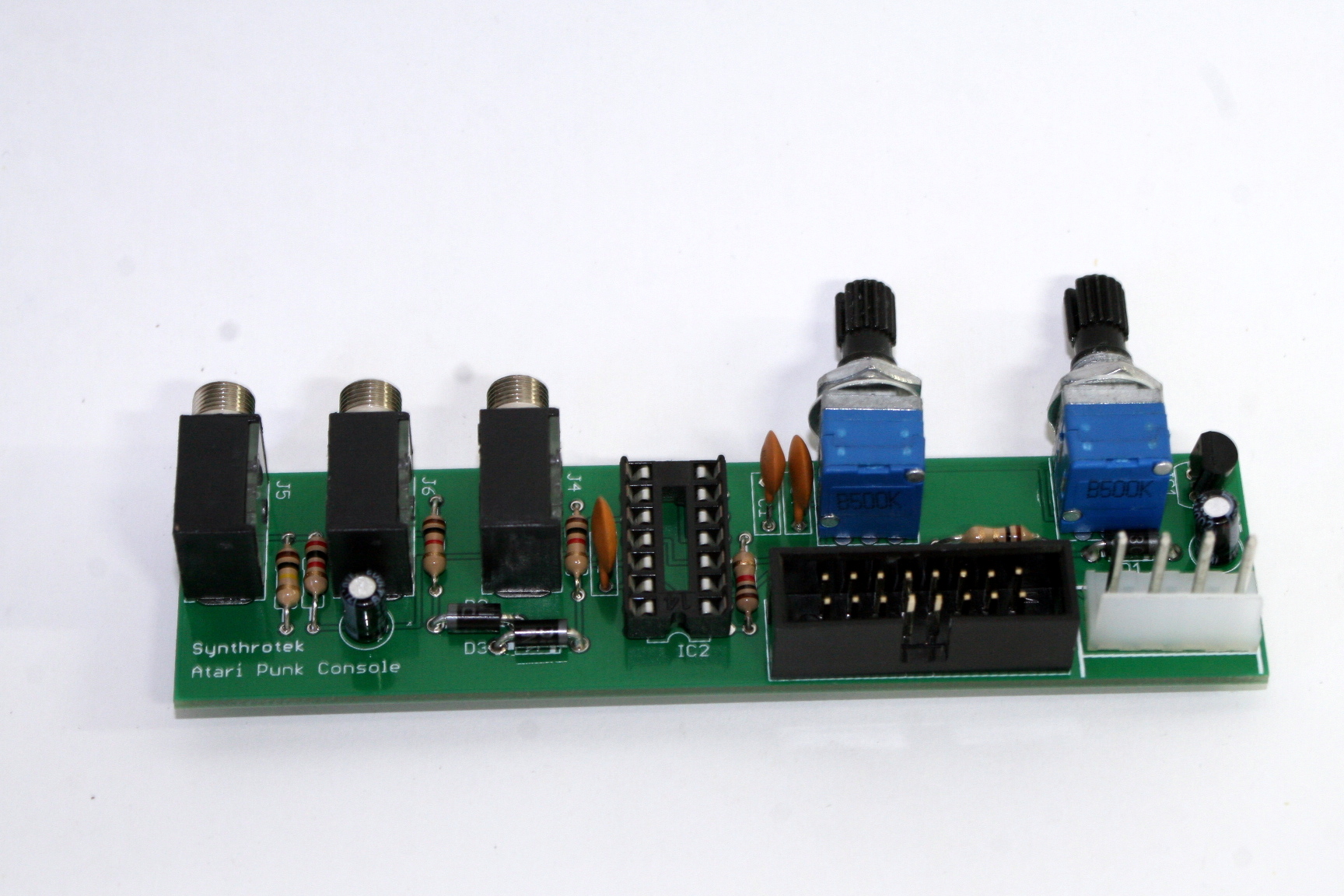
Eurorack and Fractional Rack Atari Punk Console Assembly Step 5
We are almost done with soldering! Depending on if you ordered the EuroRack version or the FracRack version you may only have the 16-pin shrouded header or the 4-pin molex. Match the connector to the image on the silkscreen, ensuring that the notch on the 16-pin header is aligned with the image of the notch on the PCB, or ensuring that the 4-pin molex connector latching mechanism is aligned with the image on the PCB.
Completed Circuit
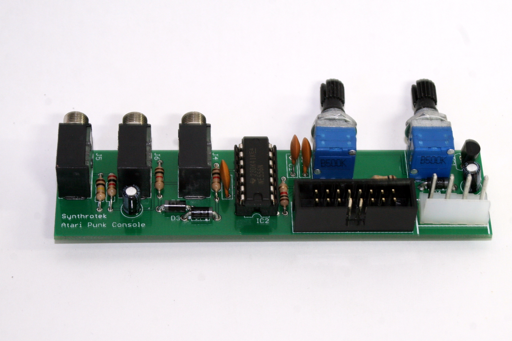
Eurorack and Fractional Rack Atari Punk Console Assembly Finished
All you need to do now is insert the 556 Timer IC into the IC socket, making sure that the notch on the IC matches the notch on the IC socket. Attach a panel, install into your Euro or Frac Rack and make some noise!
Testing Procedure
—-CONTROLS—-
Set knobs ONE and TWO fully counter clockwise on the Modular Atari Punk Console. When you monitor the output, you should hear a square wave that is fairly low, but audible. It could be anywhere around 30+Hz.
Slowly turn knob ONE clockwise and you should notice the pulse-width changing slightly until the pitch changes (up). This will keep happening as you rotate the knob until it is fully clockwise. The pitch could be anywhere around 450+Hz at this point. Now leave knob ONE set fully clockwise.
Now slowly turn knob TWO clockwise and you should notice the pitch change anywhere around 450+Hz all the way up to 13 to 15+kHz. The pulse-width will increase as well until the audio dies out when the knob is set fully clockwise.
—-CV INPUTS—-
To make sure both CV inputs on the Modular Atari Punk Console are working, set both knobs to noon and insert a bipolar CV signal into CV 1. You should notice the pitch changing. Now take the CV signal out of CV 1 and insert it into CV 2. You should notice the pulse-width changing.
By now you should be able to confirm that the Modular Atari Punk Console is working correctly.
Congratulations! You just successfully just built an Atari Punk Console module from Synthrotek! You can check out all the info on the module, watch a demo video, or read the quick start guide over on the product page.
Thanks for choosing Synthrotek!
Hi,
I would have a question; where are the -12 V pins on the header? If I hold the modul vertically, are they at the bottom or on the top?
Thank you for answer!
Hello,
In the last picture of the assembly instructions on this page, the -12 goes all the way on the left of the 16 pin header.
Best,
-Patrick
Hi, I think I got it working, then it died. I tried plugging it into some powered speakers, and I thought I smelled something burning. Now, the LED won’t come on, and it makes no noise. Some of the pots and inputs might have touched. How can I troubleshoot this? Or is it fried?
Thank you,
Alisdair
Hey Alisdair,
It may be something as simple as replacing a diode and/or the IC.
Are you certain the your IC/diodes are all facing the correct direction?
If you have a multi-meter, I would test each diode to make sure none of them are blown.
For future repair help, you should feel free to contact us at store@synthrotek.com
We also offer repair services for kits which I can give you more information about if you’re interested!
Best,
-Zach
@Steve Harmon
Thanks so much for the tips. I’ll go through it with the multi-meter and post what I find out : )
Okay, I have a multi-tip transformer, and I had it set up for positive polarity rather than negative. That seemed to kill the diodes. Switched both of them out, as well as the chip, just in case. Now it works!
Thanks for the support,
Alisdair