


Important Links
Product Page
Store Page
Manual
Assembly Instructions
Calibration Instructions
Bill of Materials
Capacitor & Resistor Lookup Guide
Thank you for purchasing the Synthrotek LPG (Low Pass Gate) kit! This is an intermediate build. There are a lot of stand up resistors and tight spacing. A fine solder tip is recommended. It is very important to get all the components properly soldered into the PCB in the correct placement. If you feel like you can handle it, please proceed! If not, get some help from a friend with experience or purchase a fully completed unit.
Please build according to the BOM, and not these instructions or the pictures alone. Some components may have changed since these were written, or we may not be able to get the exact looking components in the pictures.
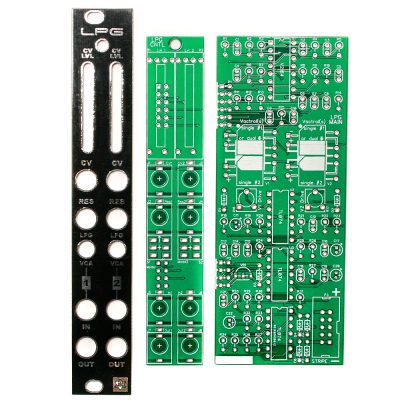
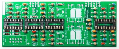
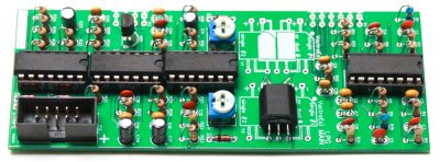
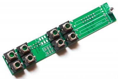
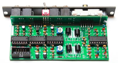
Low Pass Gate PCBs and Panel
Logic Board Diodes
The diodes are polarized, so make sure to populate them with the cathode stripe in the same direction as indicated by the silkscreen.
Once everything is in place, carefully flip your project over and solder the components in place. Clip any excess leads on the bottom of the board.
Low Pass Gate Diodes
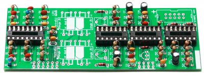
IC Sockets
Next up are the IC sockets. Take care when populating these to not bend any of the legs. Line up the notch at the end of the socket with the notch on the silkscreen. This notch indicates where pin 1 of the IC is. When you have them populated, carefully flip your project over and solder everything in place.
A trick to getting these nice and flat is to only solder one or two pins of each socket, and then reflow the solder joint while gently pushing on the top of the socket to seat it flat against the PCB. Then continue on and solder the rest of the pins.
Low Pass Gate Sockets
Ceramic Capacitors
Now we can populate the ceramic capacitors. These are non-polarized and can be inserted either direction. If the capacitor coating runs down the legs a little, make sure the coating doesn’t poke into the pads. Once they are in, carefully flip over your project and solder them in place, clipping the excess leads.
Low Pass Gate Ceramic Capacitors
Resistors
Populate the resistors on the logic board. Resistors are non-polarized, so it doesn’t matter which direction you put them on the PCB, but it will help with any troubleshooting that may arise if you line up all the tolerance bands (usually a gold stripe) on one side. This will make it easier to read the color codes on the resistors. Bend one leg of the resistor over, then place the it on the board.
Once everything is in place, carefully flip your project over and solder the components in place. Clip any excess leads on the bottom of the board.
Low Pass Gate Resistors
Electrolytic Capacitors
The electrolytic capacitors are polarized, so take care! Ensure that the longer leg (the leg that is further from the stripe indicator on the body) goes through the solder pad with the little ‘+’ symbol next to it.
Once it is aligned properly, carefully flip your project over and solder it in place, clipping the excess leads on the bottom.
Low Pass Gate Electrolytic Capacitors
Voltage Regulator & 10-Pin Power Header
Populate the voltage regulator by aligning the flat side the VR with the fat side of the silk screen. Turn over and carefully solder.
Next up is the shrouded power header. Make sure when populating this that the notch in the header is lined up with the notch designation in the silkscreen (it’s on the side closest to the edge of the PCB).
When you’re sure that it is oriented correctly, carefully flip your project over and solder it in place. Use the same trick as the IC sockets to get it nice and flush with the PCB.
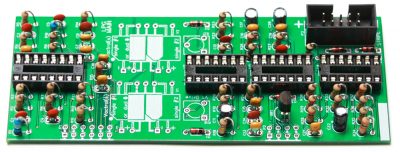
Low Pass Gate 10 Pin Power Header
Trimmer Resistors
Now populate the two trimmer potentiometers, carefully turn over and solder in place.
Low Pass Gate Trimmer Pots
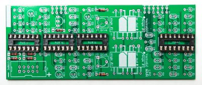
ICs and Vactrols
First insert the ICs into their sockets. You will need to bend the legs inward a little to make them fit. Match up the notch on the ICs with the notch on the socket and PCB silkscreen. Make sure that all the legs are firmly seated in the socket.
Low Pass Gate Vactrols and ICs
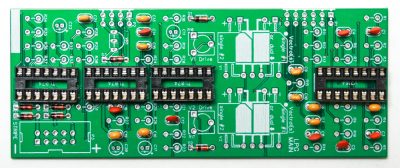
Vactrol selection is a CINCH with the Synthrotek Low Pass Gate Kit. The silk screen and pads are designed to EASILY take your vactrols of choice. You can use two vactrols per channel or 1 dual vactrol per channel.
Option 1:
When using a dual vactrol like the Xvive 5C3/2 insert the vactrol as shown below. Align the notch on the vactrol with the DUAL silkscreen (all white) notch as shown below.
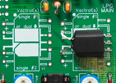
Option 1 (single vactrol)
Option 2:
If using two vactrols per channel (such as the VTL5C4 or NSL-7053), align the dot on the vactrol with the dot on the silkscreen, which is next to the word “Vactrol(s)”. Repeat the same for the orientation for the bottom vactrol.
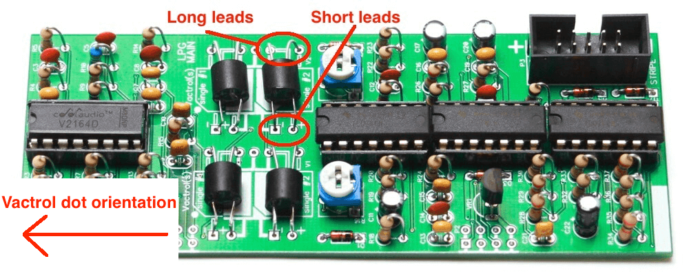
Option 2 (two vactrols)
The vactrols that we recommend (that sound the best to us) are: Xvive VTL5C4, VTL5C9 and NSL-7053 (our equivalent found here)
You can even get wild and have a different kind of vactrol in each channel!
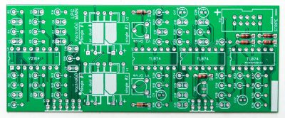
CONTROL BOARD ASSEMBLY
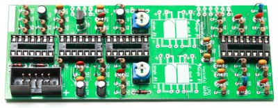
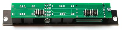
Board to Board Headers
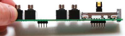
We are now going to start building the control board. We will start with the 5×2 right angle board to board headers. Make sure when you populate these that the side of the header without the bend in it goes through the control board. The black plastic stopper should be resting against the board (see image below).
Make sure that you get these seated nice and flat against the board to ensure that everything will fit behind the front panel, and be at a nice 90 degree angle to the control board.
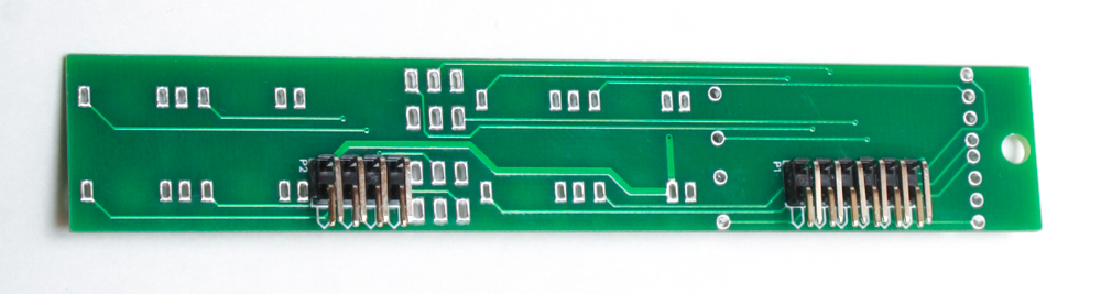
Low Pass Gate Board to Board Connectors
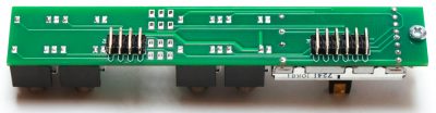
It is HIGHLY recommended to solder only one of the middle pins of these headers first, then re-flow the solder and re-seat the header so it sits nice and flat. Take your time with these and make sure everything is straight and flat before soldering the rest of the pins in place.
Once they are all soldered in place, we need to clip the pins that we just soldered down a little bit so that they don’t interfere with the slide potentiometers that need to go over them.
After clipping it is highly recommended to re-flow all the solder joints on these guys, just to make sure that there aren’t any cold solder joints on these. These pads will be inaccessible after completing the build.
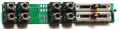
Slide Potentiometers and Jacks
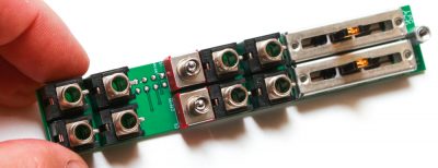
First populate the aluminum hex standoff. You can do so by inserting a metal-finish 2.5mm screw through the bottom of the board, and then spinning the hex standoff a little to get it started. Then use a Phillips head screwdriver to gently tighten the assembly together.
Next place the jacks in the board as shown below:
Low Pass Gate Jacks and Standoff
It can help to place the front panel over the jacks (and tighten some or all of the nuts) before you solder in order to align the jacks properly.
Low Pass Gate Panel Placement
Next, carefully turn the board over to solder the jacks in place. Be mindful of keeping the jacks symmetrical (makes the project look better!).
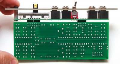
Low Pass Gate Rear
Potentiometers
Now place the pots on the board with the lever in the center, turn over and solder in place.
Low Pass Gate Pots 1
Low Pass Gate Pots Side Angle
Low Pass Gate Rear Solder
Switches
Now put the switches in place, turn over and solder. Feel free to again add the panel if that helps.
Low Pass Gate Switches
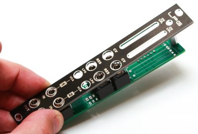
Panel Placement
Now place the panel over the control board, tighten down the black hex screw (for the standoff) and jack nuts. Be careful as to not scratch your panel!
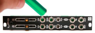
Low Pass Gate Panel Placement
Final Board Mating
When mating the two boards, take care to make sure that everything lines up at a 90 degree angle. We can use the same trick as before with the headers on the control board to make sure that the logic board is sitting as flush to the bent part of the headers, and is coming straight off the control board. Solder just one pin of the header, and then re-heat and straighten until you are satisfied with how it looks.
Low Pass Gate Panel and Board Marry
Once everything is lined up well, solder the remaining pins.
Low Pass Gate Board Connections
Congratulations! You are now ready to test and calibrate your module!
Calibration Instructions
The LPG has two trim pots that need to be adjusted:
V1 Drive (adjusts channel 1)
V2 Drive (adjusts channel 2)
These trimmers set the maximum brightness of the LEDs within the vactrols. The vactrol brightness affects several characteristics of the circuit: the output of the amplitude, the exponential curve of the filter and VCA and the overall sonic characteristics of the low pass gate.
Setup:
Grab a flathead screwdriver.
Slide the pots fully upward to 100%.
Flip the switch to LPG mode.
Patch an audio signal into channel one’s IN jack.
Patch channel one’s OUT jack to your mixer.
Using the screwdriver, adjust V1 Drive to taste. When you have finished adjusting channel 1 to taste, patch your output cable to the OUT of channel 2 and adjust V2 Drive.
Turning the trimmer clockwise will increase the LED brightness and the amplitude. You can adjust the two channels so that they have the same perceived audio output level; or you can make each channel’s vactrols respond differently. If the trimmer is turned fully clockwise, the audio output will be pretty loud. No golden ears needed here; do it however you like, and go with what sounds good to you!