


The PCB for this product has been discontinued.
Important Links
Product Page
Assembly Instructions
Bill of Materials
Layout Template
Schematic
Capacitor and Resistor Lookup Guide
Building a Dirty Boost using the DIY Stompbox Kit.
First off, you’ll need the following:
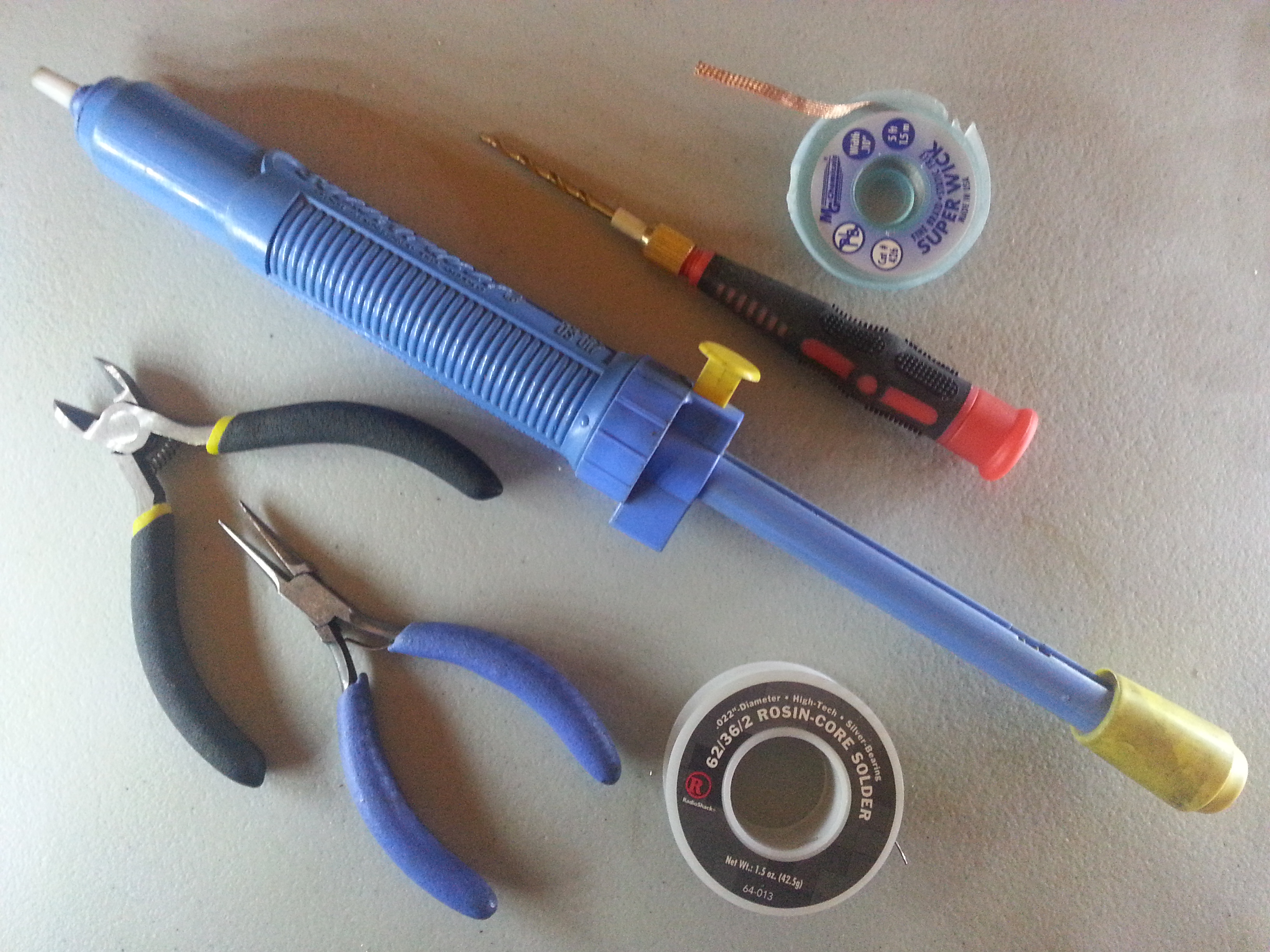
Tools:
- Needle Nose Pliers
- Wire cutters
- Solderpult (aka solder sucker or solder vac)
- Solder Wick
- Solder
- Hand drill
- Soldering Iron
- Voltmeter
Components:
- DIY Stompbox Kit

- Components for the Boost
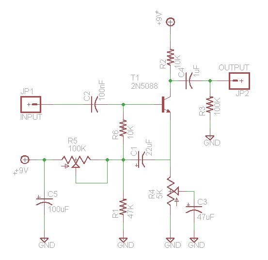
Reference Part R1 47K Ω Resistor R2 10K Ω Resistor R3 100K Ω Resistor R4 5K Ω Potentiometer R5 100K Ω Potentiometer C1 22uF Electrolytic Capacitor C2 100nF Ceramic Capacitor C3 47uF Electrolytic Capacitor C4 1uF Ceramic Capacitor C5 100uF Electrolytic Capacitor T1 2N5088 Transistor
The Build:
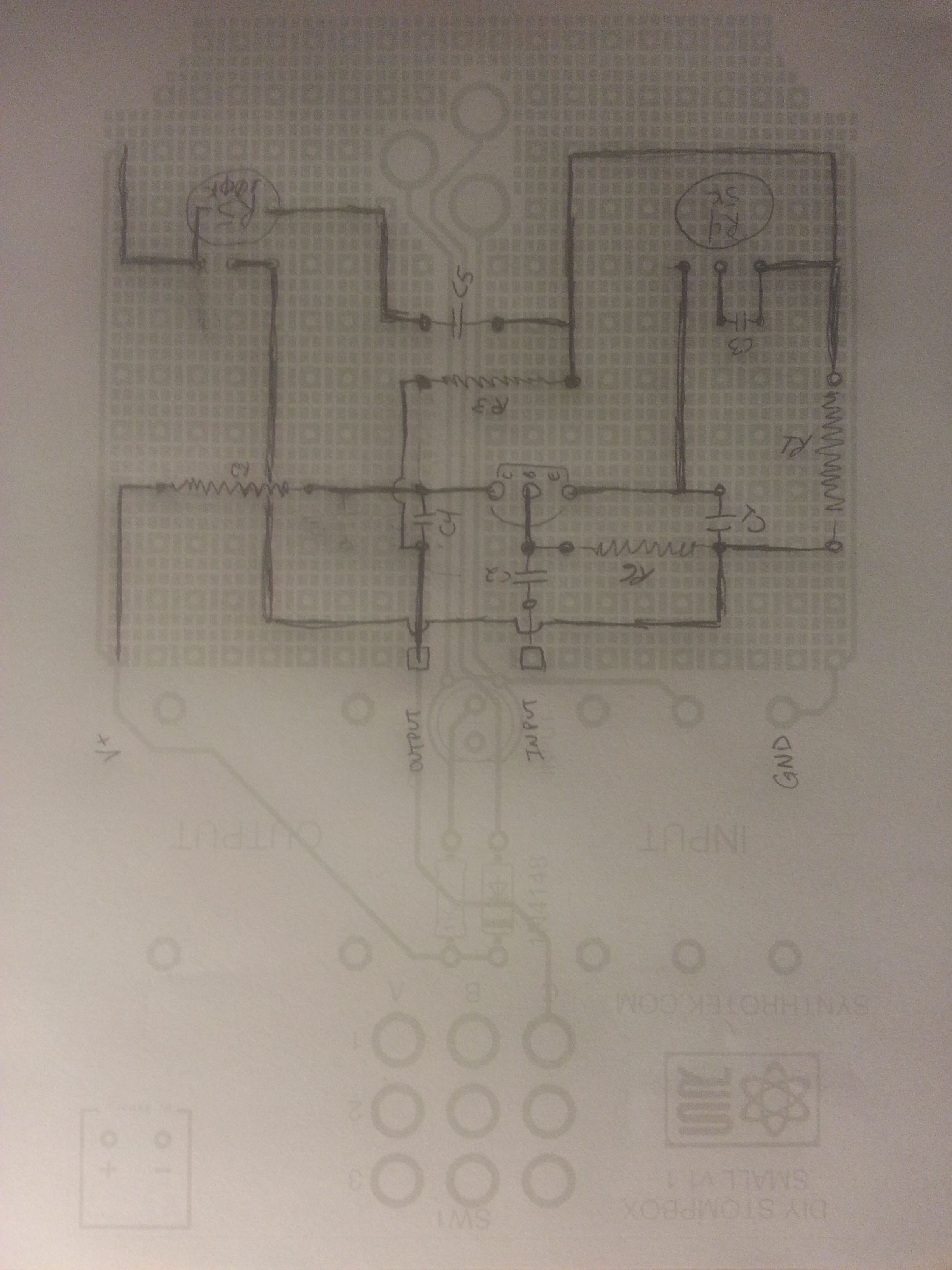
First, we looked for a suitable schematic for a Boost, which we cleaned up and have included here for your convenience.
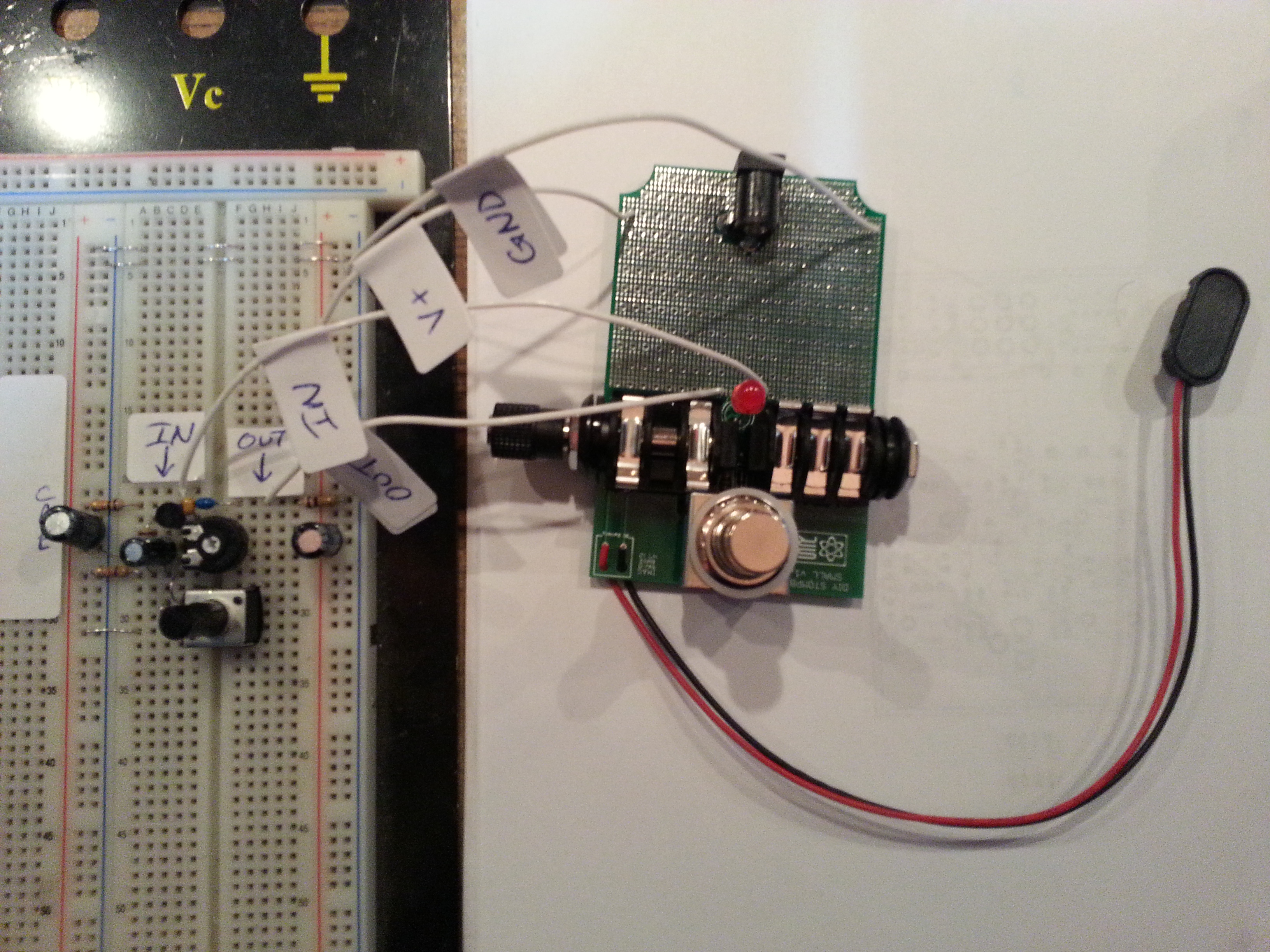
We then prototyped the circuit on a breadboard to make sure it was going to work. Schematics on the internet are never wrong, right?
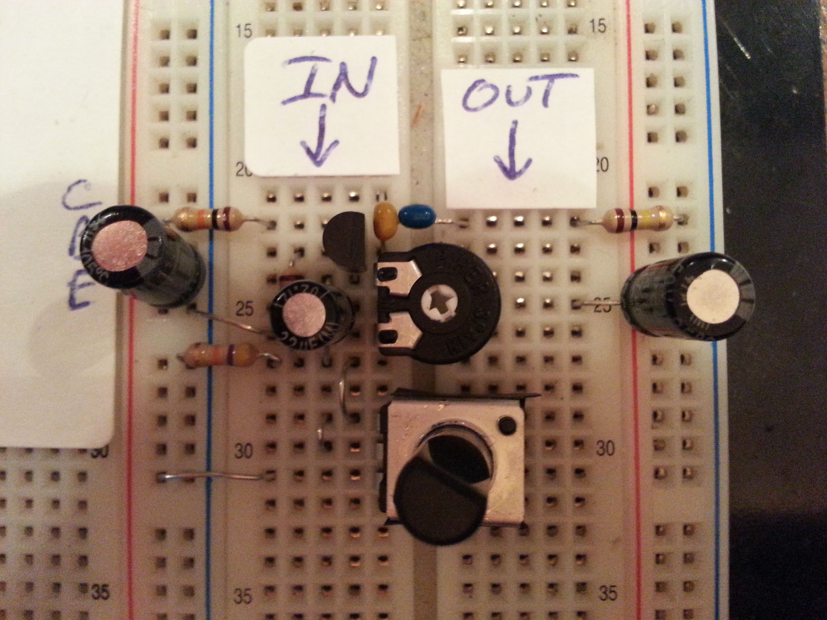
To test that the boost worked completely we wired up a skeleton DIY Stompbox Kit to the breadboarded Boost via 4 wires. Jeff said it sounded great and like a boost, but we really think he just wanted Keith to quit “playing” the guitar. Anyways, onward…
So, as with any prototype where soldering is involved you need a plan. To assist us in the planning we printed out picture of the DIY Stompbox PCB which we’ve actually turned into a template for you all to use on your projects to make things easier. Here is our plan. Note: The plan and what we actually ended up running as traces on the PCB do differ.
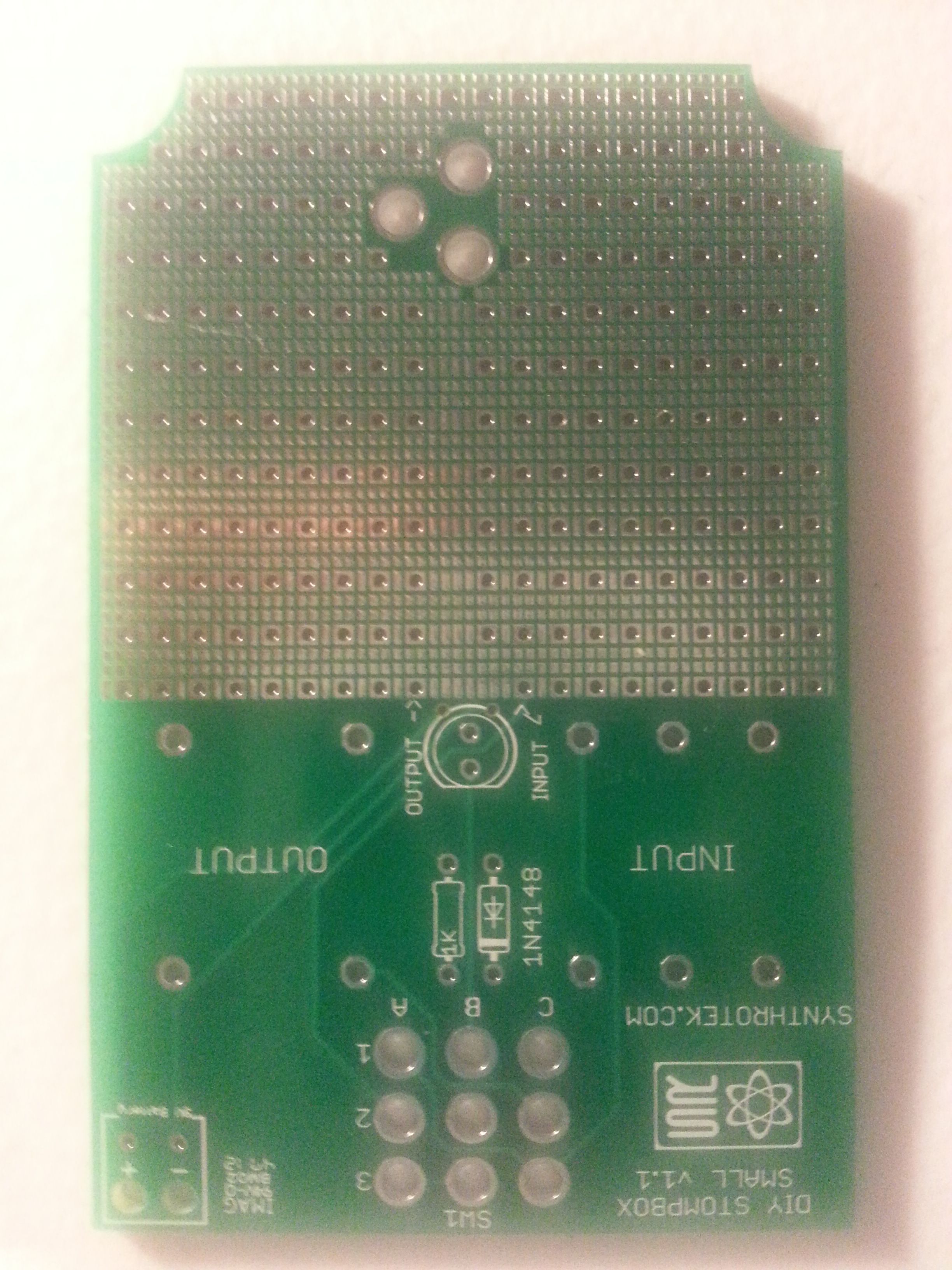
Here we go… Step 1. Board
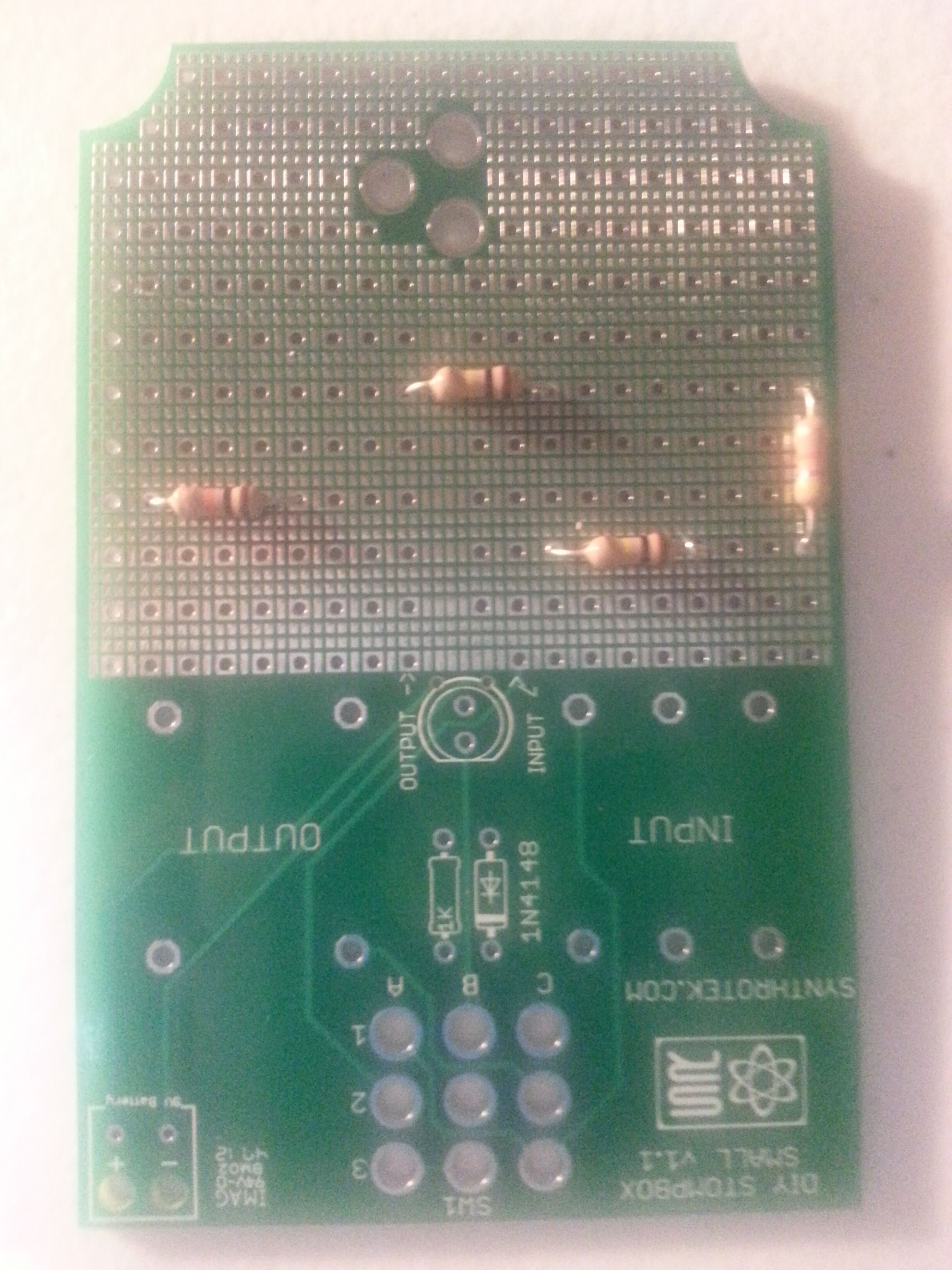
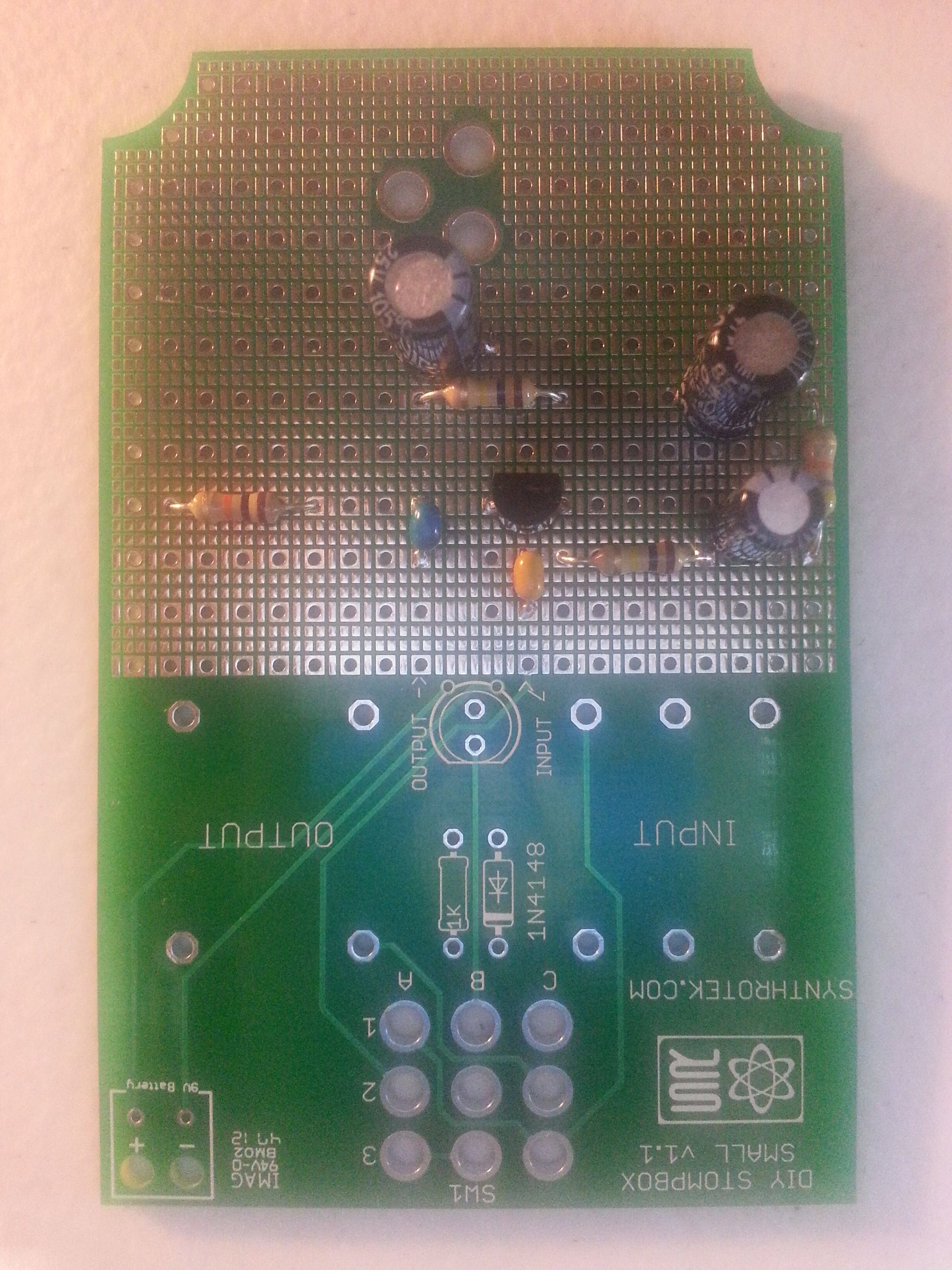
Step 2. Resistors
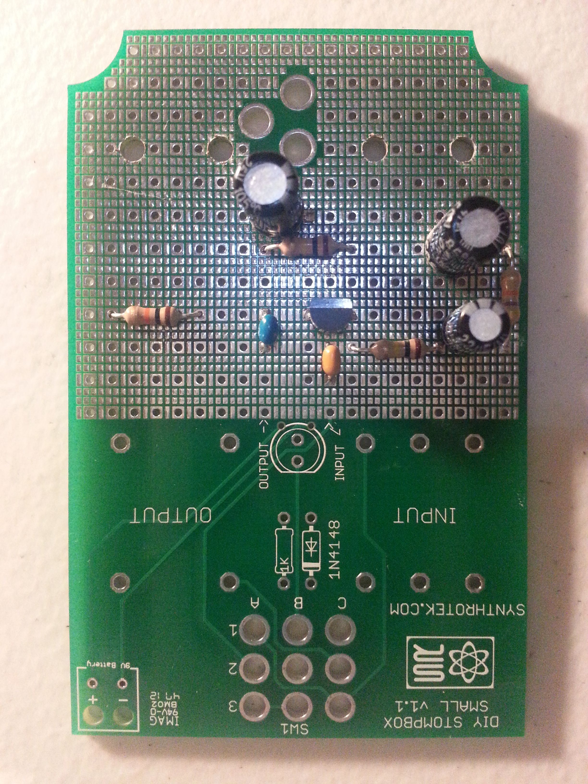
Step 3. Caps and Transistor
Step 4. Holes for the POTs. Drilling holes on a PCB does not require a drill, drill press or even a dremel. PCBs are soft enough that you can drill them very easily and quickly by hand. In prototyping this works great for those one or two holes. Check out our fancy red handled drill in the tools pictures above.
Step 5. Soldering on the POTs.
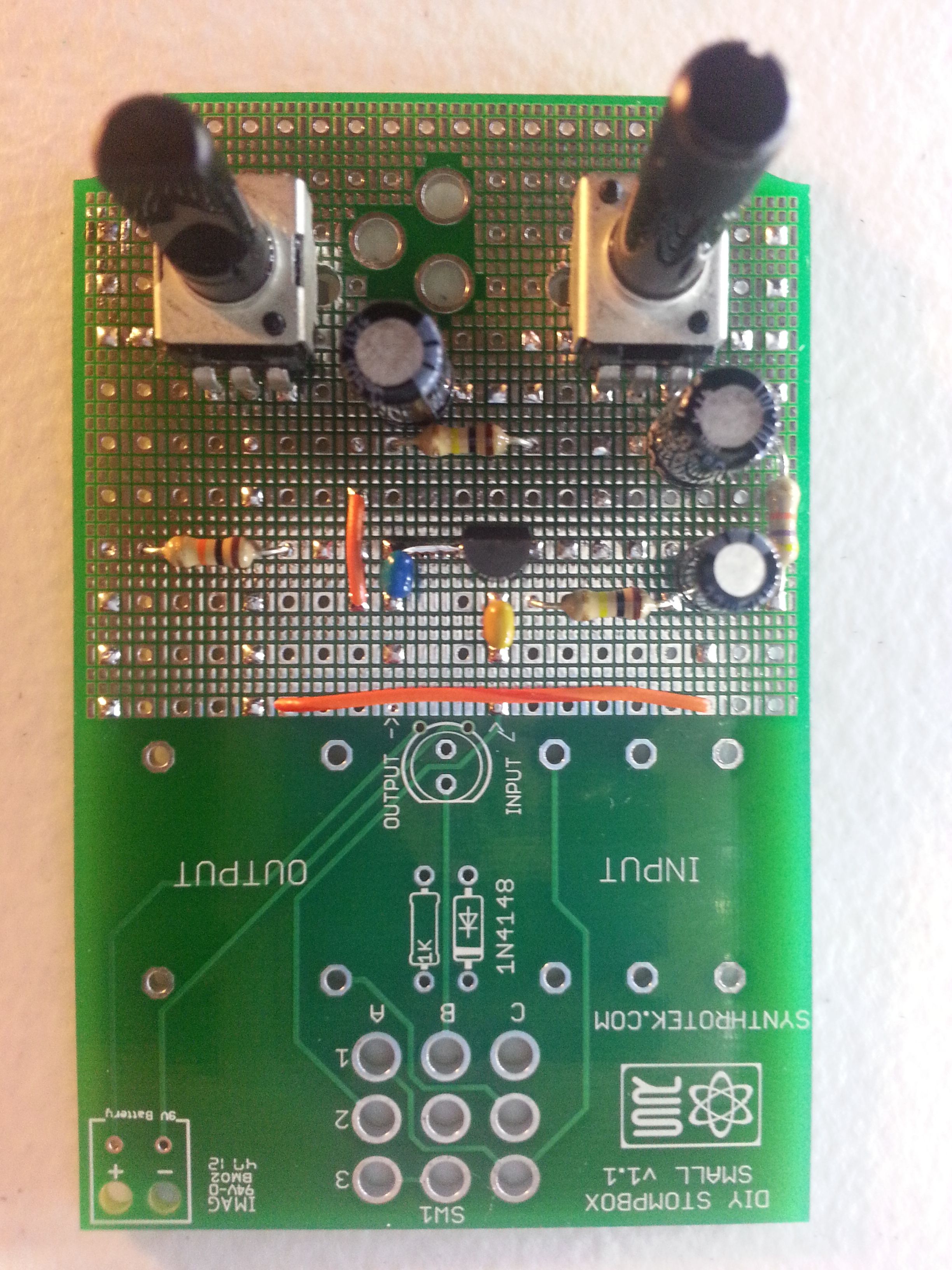
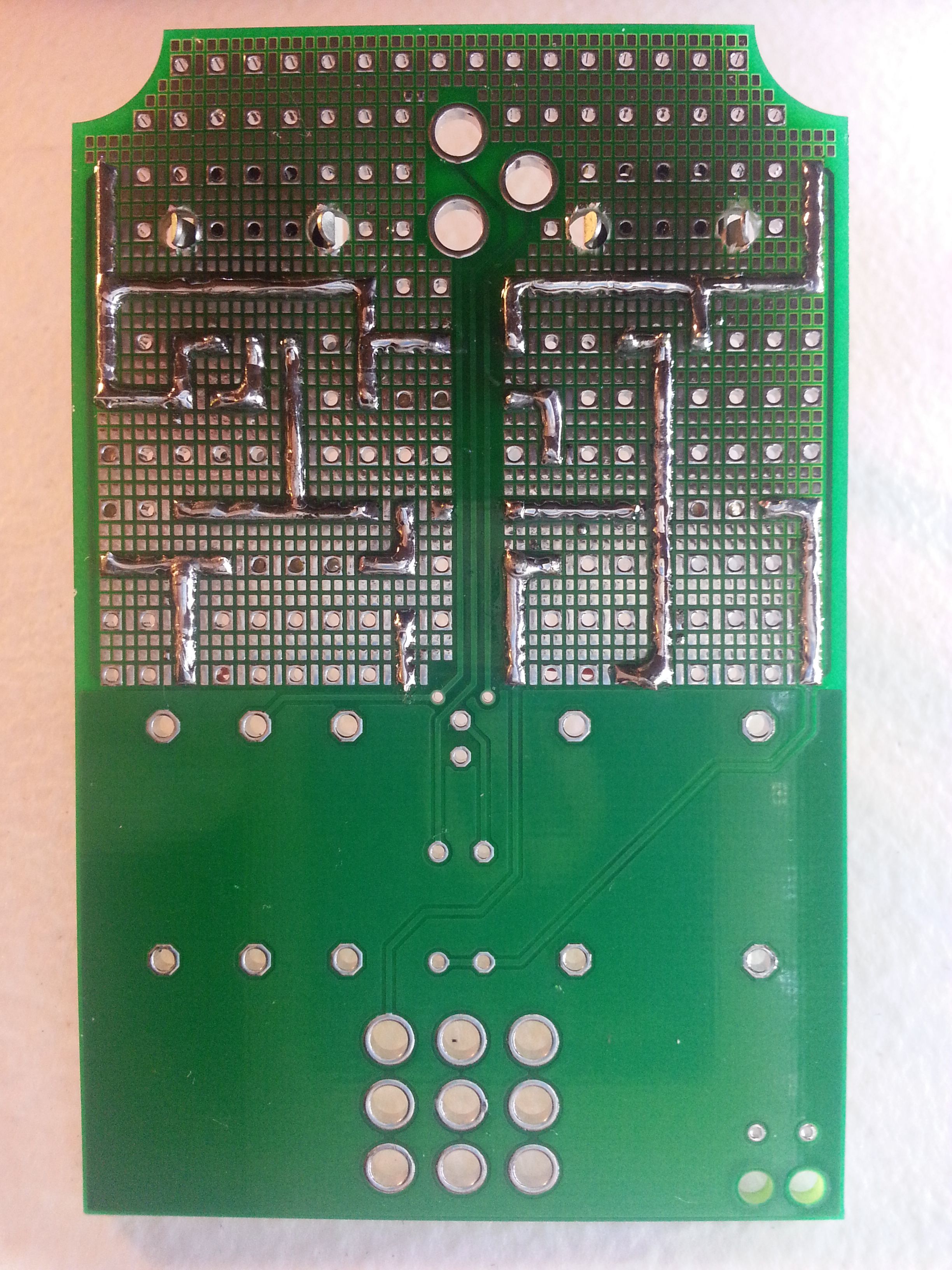
Step 6. Soldering traces to connect everything. Our trace plan failed to account for the mechanical mounting holes of the POTs so we had to adjust it a bit. We also didn’t like the placement of the pots on our plan when we were test fitting on the board so we adjusted that as well which also meant trace changes. The end result was…
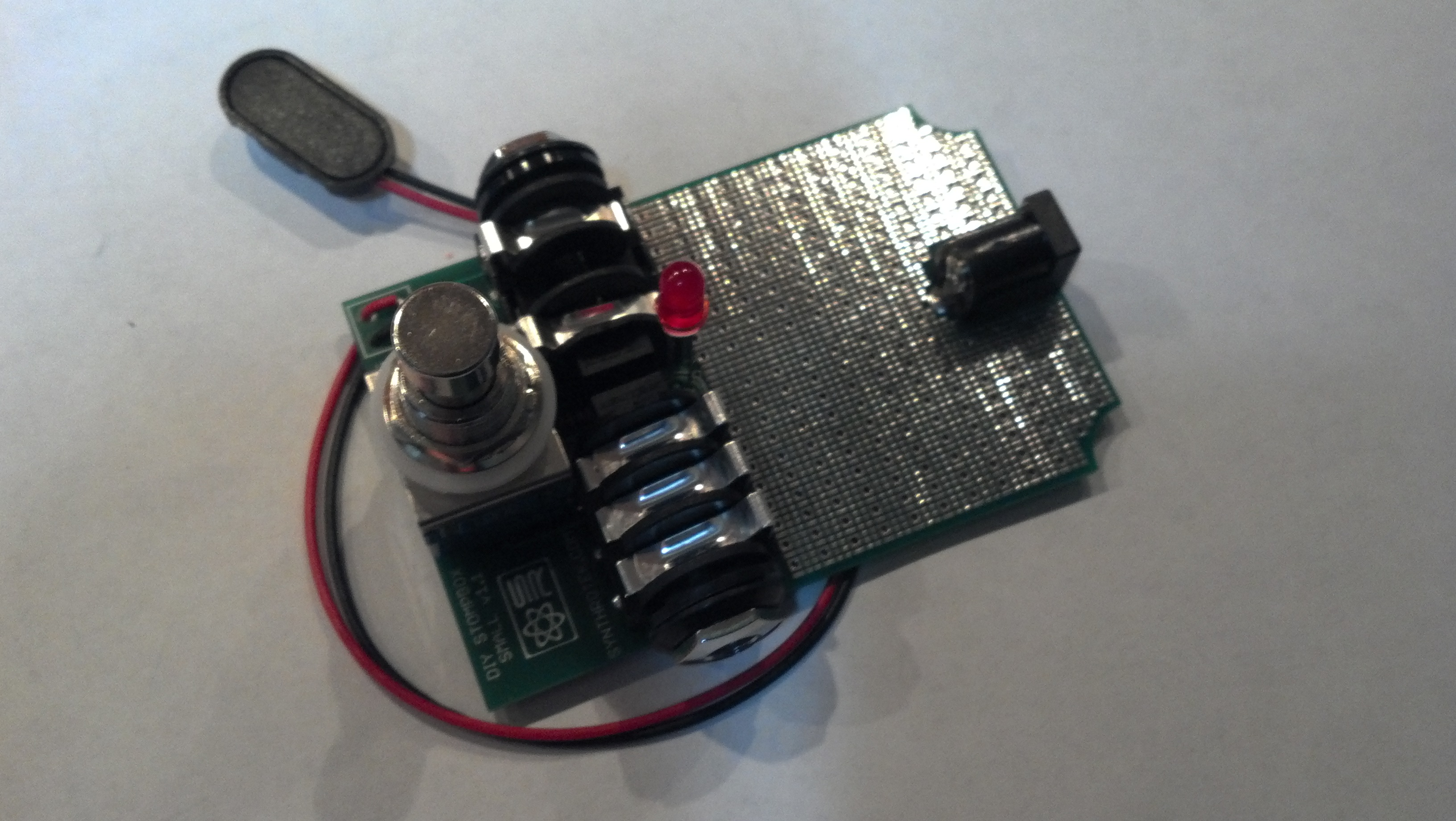
Step 7. Solder on the components for the DIY Stompbox which results in…
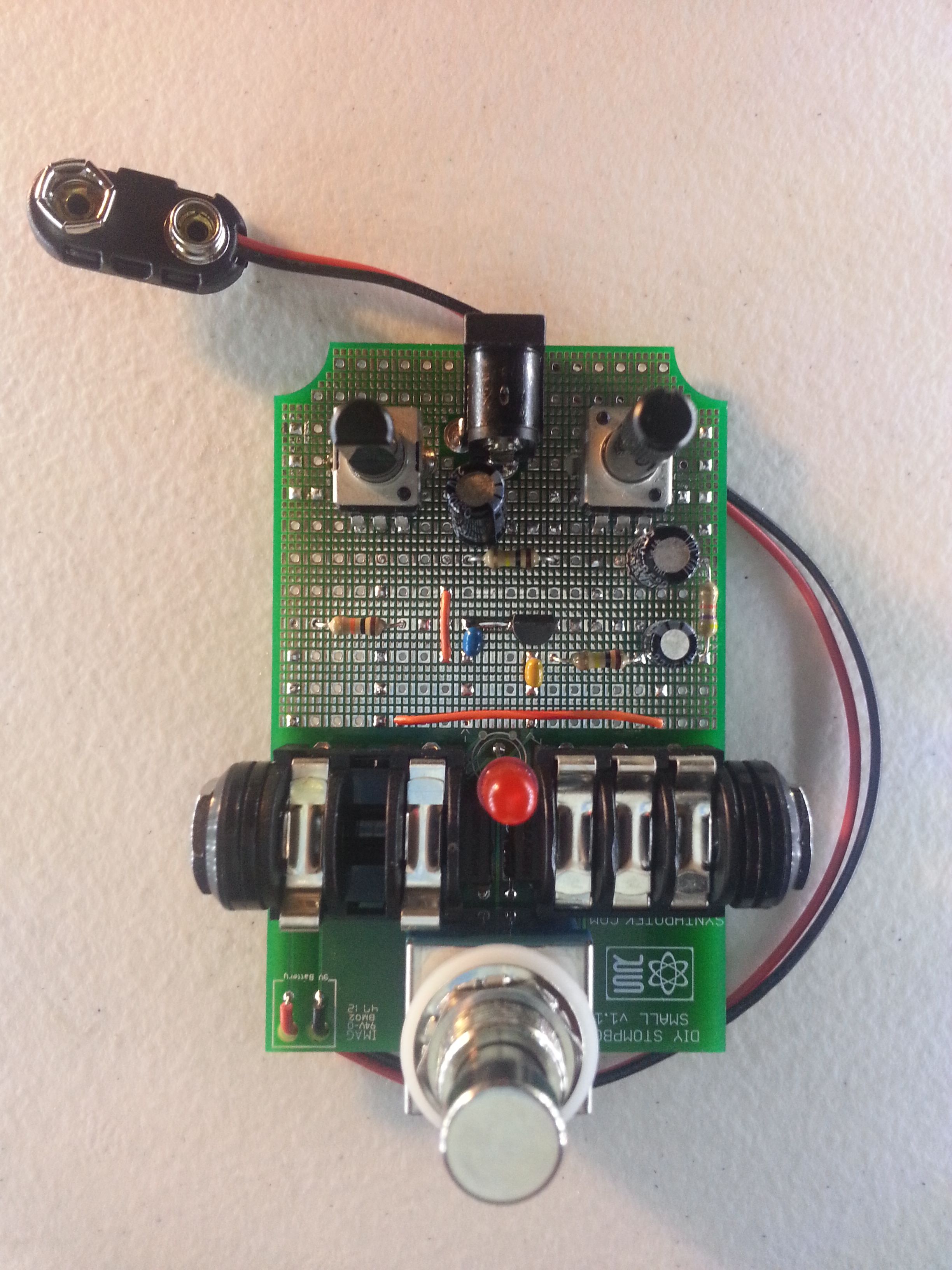
And that’s it. Check out our videos to see the real fruits of our labor.
Hi, since I have never before built a stomp box I have a question that is probably stupid. Do you sell a kit containing the components for this box? If not: is the component list on this page (http://www.synthrotek.com/kit-assembly-instructions/effect-pedals-assembly-instructions/diy-stompbox-assembly-instructions/diy-stompbox-boost-demo-project/) all I need to get the correct parts in any store I go to?
regards
tellef
oslo
Hello Tellef. Sadly, the DIY Stompbox is no longer being made. We sold the last of the PCBs a few months ago.