


Important Links
Product Page
Store Page
Quick Start Guide
Assembly Instructions
Bill of Materials
Capacitor and Resistor Lookup Guide
MST Expressor Assembly Instructions
Thank you for purchasing the MST Expressor module kit!
Extra tools/supplies needed: sandpaper
ATTN: Please follow the BOM and these instructions and don’t populate from the PCB or these instruction pictures alone. Please note that components may change over time, so please look over your parts and check the codes first.
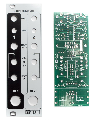
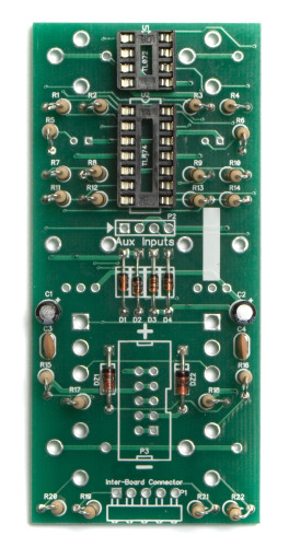
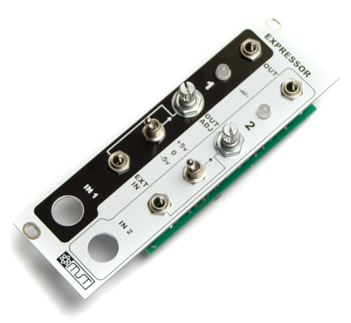
MST Expressor PCB and Panel
Let’s Begin!
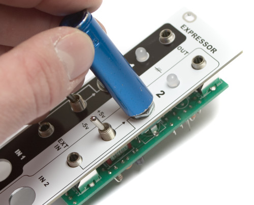
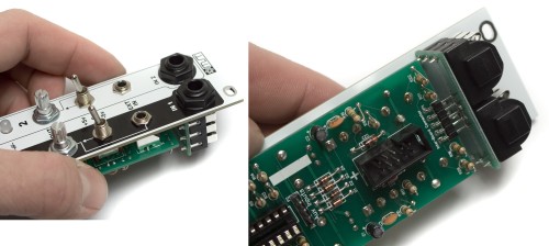
Breaking apart the PCBs
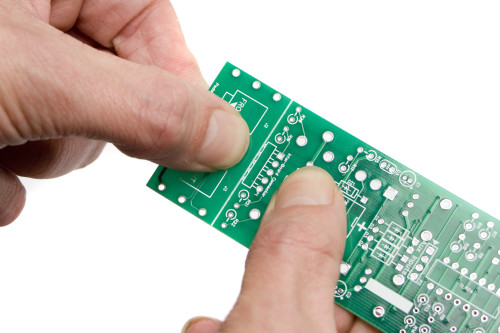
First up, we need to separate the two boards from each other. Hold the PCB like shown above, and gently bend the boards until they break at the seam.
Sanding down the rough edges
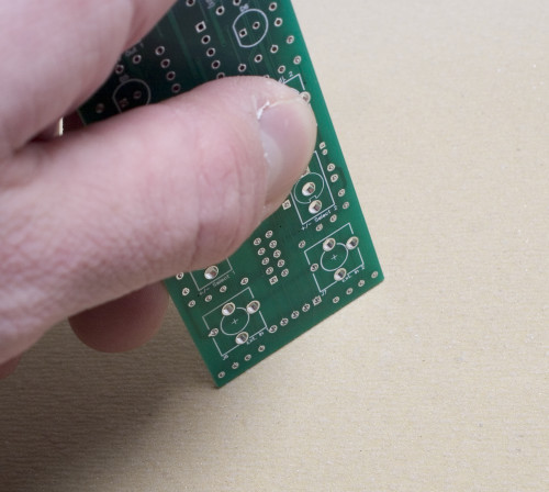 Next, we need to sand down the rough sides so that it is easier to work with. You only need to sand them until they feel smooth.
Main Board
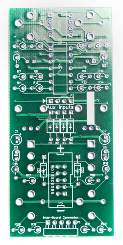
We are going to start with the main board, building in height order, from shortest component to tallest component.
Diodes
Start by populating the diodes. These are polarized, so pay close attention to where the stripe on the diode is, and match it with the stripe on the silkscreen.
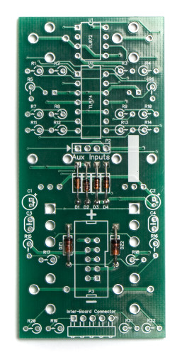
DZ1 and DZ2 are Zener diodes and are very different from the 1n4148 diodes that go in D1 through D4.
Once you have them all in the board, go ahead and flip your project over, solder everything in, and clip any excess leads.
Ceramic Capacitors
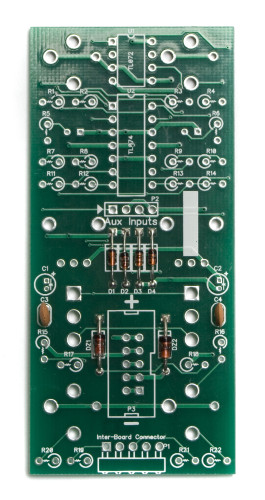
Next up are the ceramic capacitors. These are non-polarized, so they can be placed in any orientation on the board. I recommend placing them so that you can read the code printed on them from the outside, so that if you need to troubleshoot later, you can read the code easily. Once they are in, flip your project over onto a flat surface, solder, and trim any excess leads.
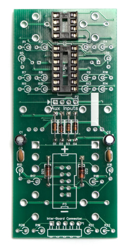
IC Sockets
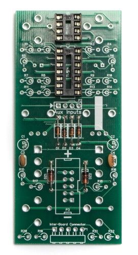
Now we can populate the IC sockets, U1 and U2. Make sure that when you do this that you align the half moon notch (on the top in the picture above) with the same looking notch on the silksckreen. This will assure that you can align the ICs properly later.
To help get them nice and flat, solder only one pin of the sockets first, and then check for flatness. If they are uneven, you can re-heat the solder pad (don’t overheat it) and gently press it down flat.
Now solder all the remaining pins on the sockets.
Electrolytic Capacitors
Next are the electrolytic capacitors. These are polarized like the diodes, but these have a stripe going down one side to indicate the cathode. Make sure that when you populate them that the cathode (stripe) is pointing away from the ‘+’ marking on the silkscreen. Once they are in, go ahead and flip it over, solder and clip your leads, like before.
Resistors
Up next are the resistors. The MST Expressor uses stand up resistors to save space. They take a little more prep than a normal resistor, but save a lot of board space. Start by bending one leg over completely so that it is parallel with the body, and other leg. If both legs are pointing in the same direction, you’re good to go. Once you have all the resistors of the same value bent into shape, insert them into their proper spots as per the Bill of Materials.
Repeat this process for each value of resistor, and once you are done, carefully flip the whole thing over onto a flat surface. Now you can solder them in place and trim the excess leads.
4 Pin Header and Power Connector
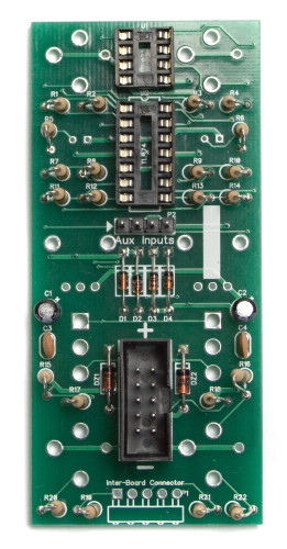
Insert the 10 pin header, aligning the notch on the header to the notch on the silkscreen. The 4 pin header (Aux Inputs) and the 10 pin power connector are roughly the same size vertically, so we recommend soldering them in at the same time. The power header has a notch cut out of one side of it. Make sure to match this notch to the same one in the silkscreen on the PCB.
Once both headers are in, double check which way the power header is facing, then flip it over onto a flat surface and solder them in. You can use the same trick here as you did with the IC sockets, where you only solder one pin first, then double check and finish soldering the rest of the pins.
Jacks, Pots and Switches
IMPORTANT: Do not solder anything yet! The front panel must be fitted to everything before anything is soldered.
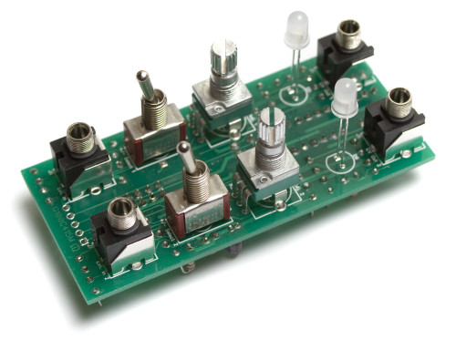
First, populate all the hardware as shown above.
NOTE: The LEDs used in the MST Expressor are Bi-Polar, meaning that they can be populated either direction and will still function. When we build the Expressor here at Synthrotek, we insert the LED backwards from how it is marked on the silkscreen. This will show positive voltage as red and negative voltage as green, just like the MST VC LFO.
If you want the LEDs to light up GREEN when there is a positive voltage being sent out, and RED when a negative voltage is being sent out, insert the LEDs so that the flat side of the LED matches the flat side on the silkscreen.
If you want the LEDs to light up RED when there is a positive voltage being sent out, and GREEN when a negative voltage is being sent out (the way Synthrotek builds it), you MUST insert them OPPOSITE of what the silkscreen shows. This means you need to align the flat side of the LED on the opposite side of where the silkscreen shows.
Do not solder anything yet!
Front Panel Placement
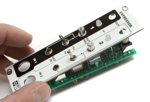
Now you can place the front panel onto the hardware from the previous step.
Tighten the Hardware Down
Now you can place washers and nuts on the potentiometers and jacks, and use a 10mm socket to tighten the potentiometers, and an 8mm socket to tighten the jacks and switches. (Don’t overtighten them!)
Then flip the project over and solder everthing into place.
Congrats! The main board is done. Time to move onto the secondary board.
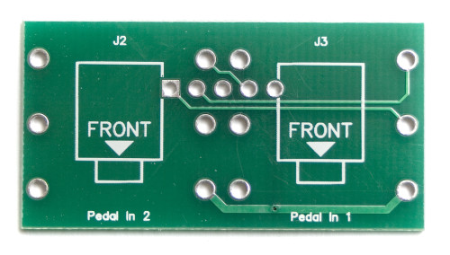
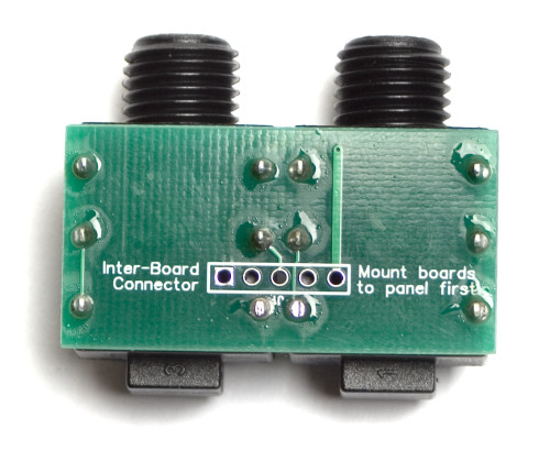
1/4″ Jacks
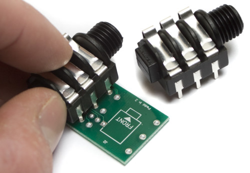
First, insert the 1/4″ jacks into their respective spots, making sure to both point the opening towards where the silkscreen indicates the front is, and that they are populated on the side that has the markings J2 and J3 (shown above).
Then you can flip it over and solder them into place. You can use the same trick as the IC sockets and the headers on the main board to get these guys flat. Solder one pin first, then make sure they are straight and flat, (re-heating when needed) and then solder the rest of the pins.
Clipping the Jack Leads
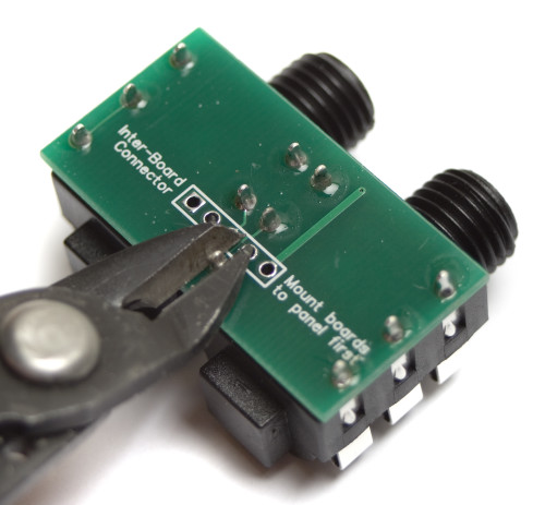
In order to make it easier to solder in the 5 pin right angle header, we are going to clip two of the pins on the jacks, so they don’t interfere with the soldering iron. The two inside pins on the back of the board are the ones that need to be clipped.
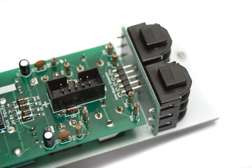
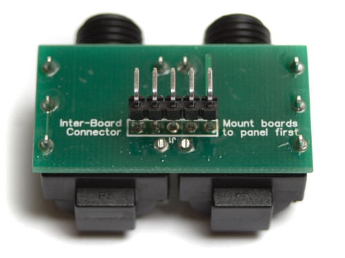
5 Pin Right Angle Header
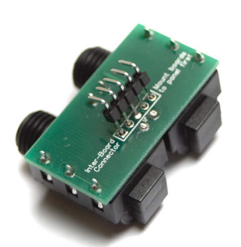
Now we are going to solder in the 5 pin right angle header that connects the two boards together. Insert it into the slot, with the short pins facing the front of the board as shown above. Then solder ONLY the middle pin into the board.
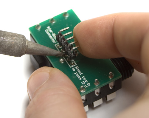
Next, reheat the middle pin, and GENTLY apply pressure to the header until it is standing straight up and down, like shown above.
Do not solder the rest of the pins yet.
Test Fit
Now we are going to test fit the secondary board to the main board by inserting the jacks into the front panel, as shown above. If the 5 pin right angle header doesn’t fit quite right, pull it back out and repeat the step above to adjust the angle of the header until it fits, without having to apply pressure.
Finish Soldering the Right Angle Header
Now you can finish soldering the 5 pin right angle header to the Secondary board.
Final Board Assembly
Next, insert the secondary board back into the front panel (and the main board) and tighten the plastic nuts down tight. There should be very little to no play in the boards after tightening the nuts down.
Once everything is secure, solder in the 5 pin right angle header where it mates with the main board.
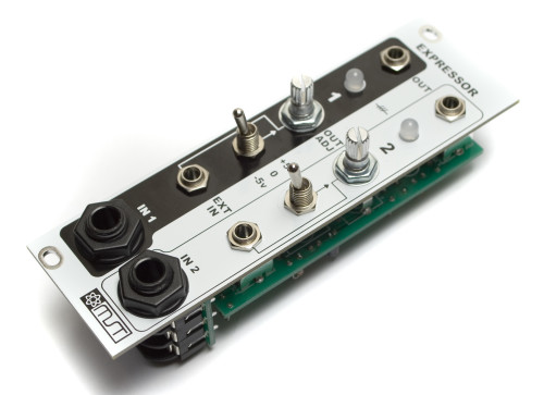
Completed Module
Congratulations! You’ve just completed building the MST Expressor Module!
If you seem to be having issues with your MST Expressor module after building it, please check out the Troubleshooting Guide for some great tips and tricks on soldering, and what to look for when hunting down bugs in your build. If you are still having issues after that, feel free to email us at store@synthrotek.com.