


Important Links
Product Page
Store Page
Manual
Assembly Instructions
Calibration Instructions
Bill of Materials
Capacitor & Resistor Lookup Guide
Thank you for purchasing the Synthrotek VCO (Voltage Controlled Oscillator) kit! This is an intermediate build. The board to board headers need to be done precisely and the IC is not socketed. There are some solder joints that are very close to components. A fine solder tip is recommended. It is very important to get all the components properly soldered into the PCB in the correct placement. If you feel like you can handle it, please proceed! If not, get some help from a friend with experience or purchase a fully completed unit.
Please build according to the BOM, and not these instructions or the pictures alone. Some components may have changed since these were written, or we may not be able to get the exact looking components in the pictures.
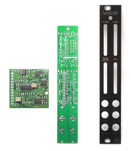
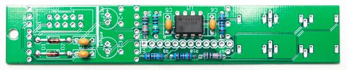
Synthrotek VCO PCB/Panel
Control Board Diodes
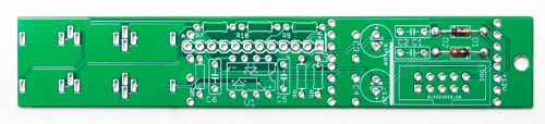
VCO Diodes
The diodes are polarized, so make sure to populate them with the cathode stripe in the same direction as indicated by the silkscreen.
Once everything is in place, carefully flip your project over, and solder the components in place. Clip any excess leads on the bottom of the board.
Resistors
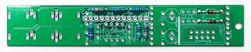
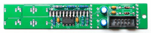
Synthrotek VCO Resistors
Populate the resistors on the control board. Resistors are non polarized, so it doesn’t matter which direction you put them on the PCB, but it will help with any troubleshooting that may arise if you line up all the tolerance bands (usually a gold stripe) on one side. This will make it easier to read the color codes on the resistors.
Once everything is in place, carefully flip your project over, and solder the components in place. Clip any excess leads on the bottom of the board.
Control Board IC
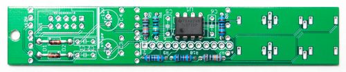
Synthrotek VCO IC
Now, insert the IC into the PCB. You will need to bend the legs inward a little to make them fit. Match up the notch on the IC with the notch on the PCB silkscreen. Turn over and solder.
Ceramic Capacitors
Synthrotek VCO Ceramic Capacitors
Now we can populate the ceramic capacitors. These are non-polarized and can be inserted either direction. If the capacitor coating runs down the legs a little, make sure the coating doesn’t poke into the pads.
Be sure to get C5 and C6 fairly close to the board, otherwise they will get in the way of the logic board.
Once they are in, carefully flip over your project and solder them in place, clipping the excess leads.
Board to Board Header
VCO Board to Board Connector
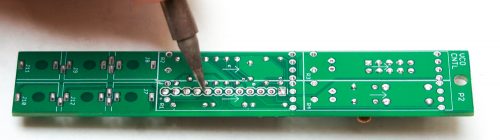
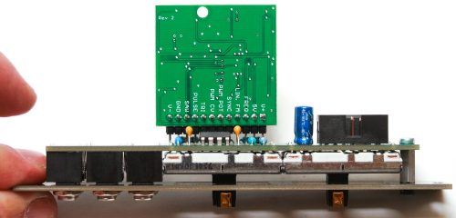
We will start with the 12×1 right angle board to board headers. Make sure when you populate these that the side of the header without the bend goes through the control board (see the picture). Place the PCB on a flat surface (or use some of the blue tape from your kit) and then place the right angle header as shown above in the PCB (like the photo above). The non-bent pins must sit flush with your flat surface so that the header is raised a few millimeters from the back of the board. Blue tape is recommended to keep the pins from protruding through the board. You will need this extra space to place the logic board properly!
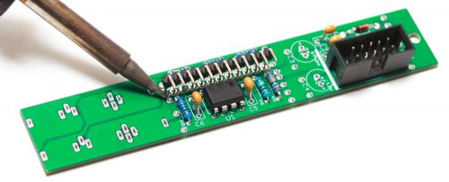
Solder the last pin on the end from the back side of the board as in the picture above. You will be soldering between the board and the plastic part of the header. Reflow the solder joint and adjust the header so that it sits at 90 degrees.
Synthrotek VCO Header Pin Soldering
Now flip the board over. As you can see the pins are NOT protruding fully through the bottom of the board. After you make sure that your board to board connectors are placed well, solder them in place as shown above. Make sure your soldering iron makes contact with both the via and the pin. It’s easy to make a cold solder joint accidentally since the pin is not sticking out very far from the board.
10 Pin Power Header
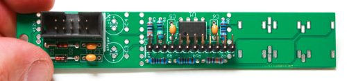
Synthrotek VCO 10-pin Power Connector
Next up is the shrouded power header. Make sure when populating this that the notch in the header is lined up with the notch designation in the silkscreen (it’s on the side closest to the edge of the PCB).
Electrolytic Capacitors
Synthrotek VCO Electrolytic Capacitors
The electrolytic capacitors are polarized, so take care! Ensure that the longer leg (the leg that is further from the stripe indicator on the body) goes through the solder pad with the little ‘+’ symbol next to it.
Before proceeding…
Trim your leads fairly close to the PCB so that the slide pots can fit flush on the board. They shouldn’t be fully flush (except for the 12 pin header), they should be small mounds. The leads on the shrouded header especially need to be trimmed. Check your work by inserting the slide pots; they should be able to lay flat against the PCB. Then remove the pots from the board.
Reflow your solder joints before proceeding!! The slide pots will cover up all your solder joints so far, so you won’t be able to access them again. Make sure that when you reflow the 12 pin header joints that your iron again makes contact between the via and the pin.
Slide Potentiometers, Jacks and Hex Standoff
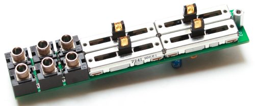
Synthrotek VCO Jacks, Pots and Standoff
First populate the aluminum hex standoff. You can do so by inserting a metal-finish 2.5mm screw through the bottom of the board, and then spinning the hex standoff a little to get it started. Then use a Phillips head screwdriver to gently tighten the assembly together.
Next up are the slide potentiometers and jacks. Center the pot sliders as in the picture above. The pots will only fit in the PCB one way, but the legs can get a little bent during shipping or general handling, so take your time and make sure they all get fitted properly into their respective solder pads. Take time as well to get the small pins of the jacks in just the right place.
The protruding pins on the jacks are the ground pins, so it is ok for them to touch each other (J7/J12, J8/J9 specifically).
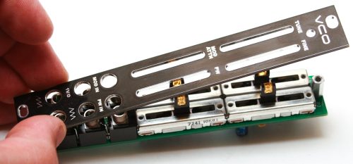
Synthrotek VCO Panel Placement
Carefully lay the front panel over the control board. Hand tighten the nuts and the standoff screw, then turn over and solder in place.
Connecting Main Board to Control Board
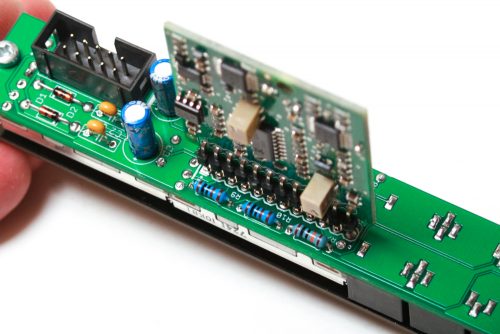
The main board is the brain of this product and comes preassembled. Align the main board with the control board header pins exactly as shown below.
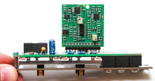
VCO Main Board Connection
Turn the board around and solder it at a 90 degree angle from the control board. It helps to just solder one pin first then straighten out as needed. Once in place, solder the rest of the pins.
Synthrotek VCO Main Board Placement and Soldering
Congratulations! You can now carefully tighten your jack nuts and standoff screw a little more (not too much!) and you are ready to test and calibrate your new analog VCO!
VCO Complete Build!
Calibration Instructions
There are two trimmers for calibrating 1V/octave pitch tracking: V/OCT & HF (high frequency). The process can be broken down into a a few steps per each trimmer for simplicity.
Here’s a video, but the instructions are also printed below the video:
V/OCT Trim
1. On the front of the panel (using the TUNE and FINE controls), tune to a fundamental frequency that can be easily verified several octaves up (e.g. 20Hz, 50Hz or 100 Hz).
2. Apply 1V to the V/oct input.
3. Adjust trimmer to 2x the initial frequency.
4. Apply 0V to the V/oct input.
5. Readjust the TUNE/FINE pots the front panel to match initial frequency.
6. Repeat steps 1-5 until 1V is 2x the original frequency.
7. Repeat steps 1-6 until the first 6-8 octaves are calibrated, or you’re satisfied with the range that is calibrated.
HF Trim
This should only affect tracking at high frequencies, where there can be a slight drop in current within the exponential generator inside of the 3340 IC.
1. Calibrate the V/oct trimmer first.
2. On the front of the panel (using coarse and fine controls), tune to a very high frequency (e.g. 2kHz, 4kHz, 8kHz).
3. Apply 1V to the V/oct input.
4. Adjust trimmer to 2x the initial frequency.
5. Apply 0V to the V/oct input.
6. Readjust the TUNE/FINE pots the front panel to match initial HIGH frequency.
7. Repeat steps 3-6 until that octave is calibrated.
8. Repeat steps 3-7 for each successive octave until satisfied.