


Important Links
Eurorack Version:
Assembly Instructions
9V Version:
Assembly Instructions
Bill of Materials
Schematic
Capacitor and Resistor Lookup Guide
EURORACK DIRT Filter Assembly Instructions
If your PCB says “2.2” in the corner, use these instructions.
If your PCB says “2.0” in the corner, CLICK HERE.
If you’re looking for the 9V version, CLICK HERE FOR VERSION 2.2
Thank you for purchasing your EURORACK DIRT filter Kit, please follow the instructions to ensure that you have a fully functioning unit. ATTN: Please follow the BOM and these instructions and don’t populate from the PCB alone. Also sometimes we cannot get the exact pictured components, so please look over your parts and check the codes first. Let’s get started!
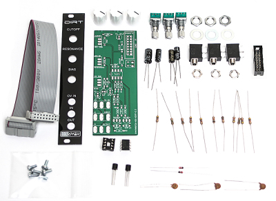
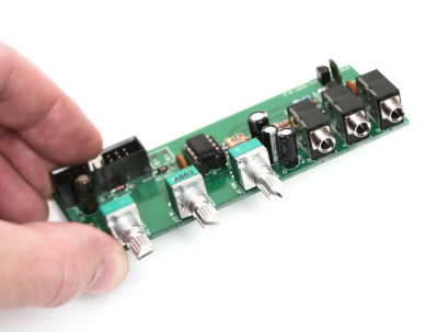
Eurorack DIRT Filter 2.2 Kit
RESISTORS & DIODES
First, start by populating the resistors and the diode, as shown below, then turn over on a firm surface to solder then clip your leads. Diodes are polarized components so you must match the black stripe on your diodes with the white stripe on the PCB silkscreen.
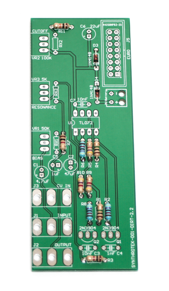
DIRT FIlter 2.2 Resistors and Diodes
Socket, IC, Power Header and Transistors
Place the IC Socket in place by aligning the notch with the notch graphic on the PCB Silk Screen. Turn over and solder. Then place the 16-Pin Power Header by aligning the notch on the header with the notch on the PCB Silk Screen, turn over and solder. Next add the transistors by matching the flat side of the transistors with the flat side on the silk screen. Turn over, solder and clip all leads.
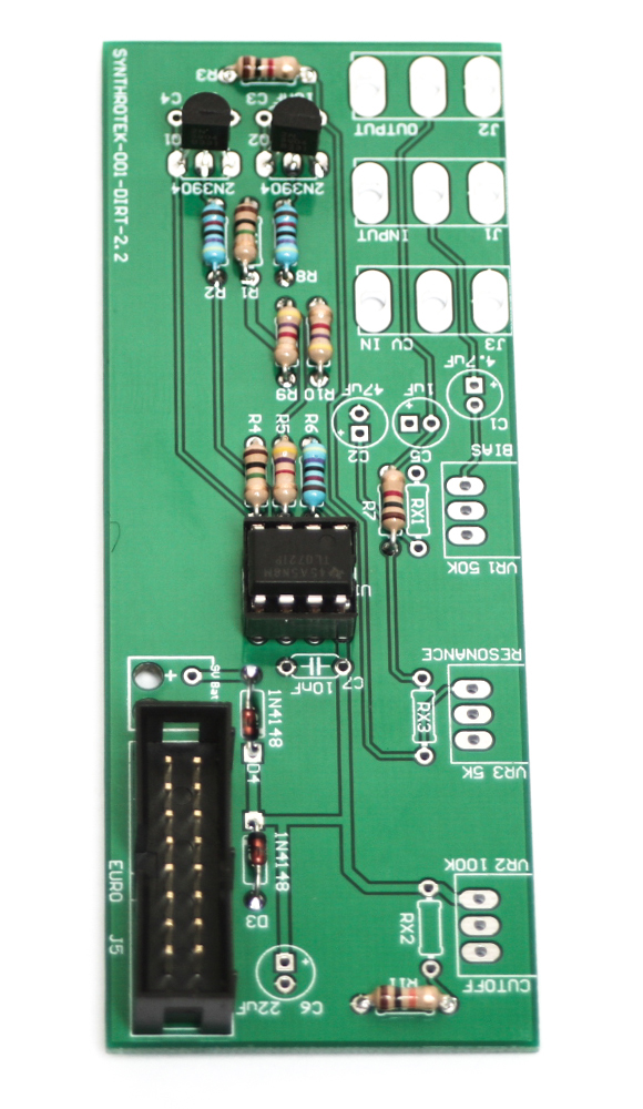
Eurorack DIRT Filter 2.2 Socket, IC, Power Header and Transistors
CAPACITORS
Place the capacitors in place and solder and clip leads. Make sure you orient the electrolytic capacitors in correctly. The longer lead needs to be inserted into the hole that has the “+” marking near it.
Eurorack DIRT filter 2.2 Capacitors
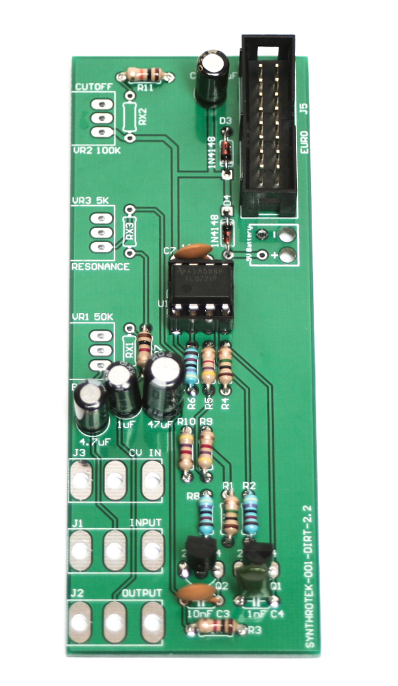
POTENTIOMETERS & JACKS
First trim the alignment nub off the pots, as this will create a ‘wanky’ front panel.

Next add the Pots and Jacks, solder then trim.
Eurorack DIRT Filter 2.2 Pots and Jacks
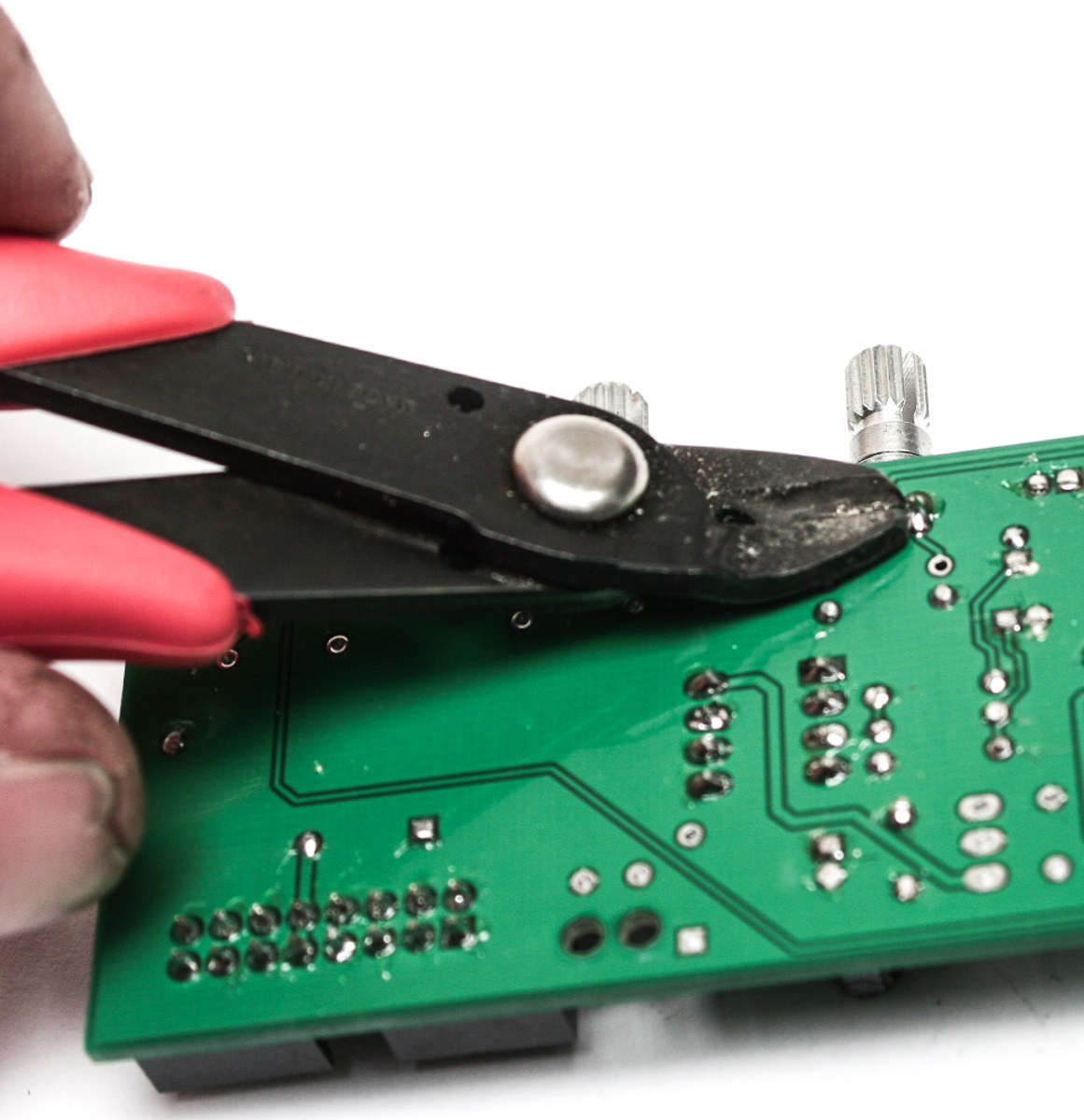
Trim Pot leads
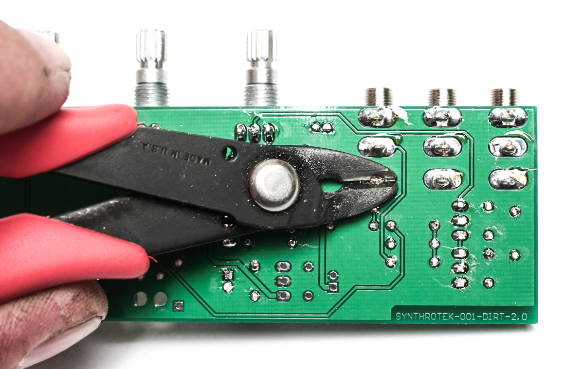
Trim Jack Leads
FRONT PANEL & KNOBS
Add the front panel to your unit and tighten down the nuts carefully and do not over-tighten. The knobs can now be added and aligned as shown below.
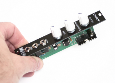
Final Eurorack DIRT Filter 2.2 Module
CONGRATS! You are now done with your project and can test the unit in your eurorack system. If you have any questions or need help debugging, please first refer to our troubleshooting guide BY CLICKING HERE. If this gets you nowhere, please contact us by email for support. Thank you again for purchasing your kit from Synthrotek!
Sweet
For the benefit of others I thought it would be worth posting this question here 🙂
Is R5 4.7k as in the BOM or 10K as marked on the PCB?
I’m going with 4.7K as your build pictures show the same value in R5 as R9 and R10.
Which is correct though?
Hi Brett, if you see a discrepancy between the PCB and the BOM, go with the BOM. It should be 4.7k. We typically make silkscreen revisions as needed when we make a new run, so it’ll change in the future.
Thanks!
Hi,
I’m not getting much response out of the cutoff knob. Feeding it raw saw, square, etc it only seem to have an effect in the 75 to 100 % range, and then it is just a squealing sound that self oscillates. Other knobs adjust this a bit, but there seems to be no point where the unit is playable, it is either self oscillating or silent.
I subbed a TL072 CP for the straight TL072, but these parts should be interchangeable right?
Any ideas?
I also noticed that in the photos above R2, R6, and R8 are 1% 47 ohm y,v,bk.
The BoM had these listed as 47k ohm y,v,o. The mouser cart gives you 5% 47k.
Try turning the bias pot, fully CW, then adjust the cutoff. This is really noisey circuit and self resonates in many areas. Not a traditional filter at all.
Any tl072 should work fine
This circuit does not requite 1% values, the 5% is fine. Always use the BOM for the most updated parts list.
@John
Same issue too! I knew I didn’t get the build wrong~
I dont believe that either of you built your circuit wrong. The DIRT needs a hotter audio signal to perform best. Most eurorack modules will kick out a signal that is hot enough. Do you have a way of boosting your signal to make sure that it is strong enough?
My second build… Even easier than the 308 rat clone. Next… Dual Triple Response VCA and Sequence 8 after. This Dirt filter is one funky unit!!!!
Thanks! we love the Dirt too, there’s nothing quite like it!
Hi,
I’m not hearing anything through the Dirt Filter, I placed all the components right, my teacher in audio hardware checked the soldering and he is very convinced it should work. Didn’t have the time to measure with a multimeter. I’m using the Chaos Nand as an audio source, patched directly in the Dirt Filter. I’m really not hearing anything except some noise, but nothing of the original audio signal comes out. Checked the troubleshooting guide but there should be nothing wrong.
What should I do?
Hello,
It sounds like you’ve taken some pretty good troubleshooting steps already, one thing to check is to make sure the TL072 is getting voltages. You could also send it in for a repair, if that sounds more appealing to you. If you want, shoot us an email over at store@synthrotek.com, and we can get you hooked up.
Best Regards,
-Patrick
Hey Patrick,
the dirt filter works now. Had to change the TL072, no worries.
Only thing is now that the cutoff knob doesn’t do much, as described earlier by others.
It sounds like the cutoff is controlled in a very short period, so on 60% open I start hearing some low frequencies, and at 90% the filter is completely open. This is only when Bias is set to 100%, when decreasing the bias, the cutoff point moves up.
Tried to boost the signal but this only makes it more filthy.
Is there a way to stretch out the cutoff knobs range?
@Roel Weerdenburg
same same same!!! same issues here as well.
Hello,
I began this build and jumped into it soldering based on the schematic, starting the diodes first 1N4148 this is also printed on the silk screen. However I did order parts based on the BOM and reviewing those materials as I began putting together other parts I realized that the BOM states using BAT85 diodes. I have finished the module but have not fired it up because I wanted to double check if these 1N4148 diodes are fine to use and/or if they will affect the sound or performance of the module, or if I should replace them with the BAT85 diodes.
Thanks!
Hey JJ,
Sorry for the confusion. Often times our schematics go through some changes by the time they come out as completed products. The Dirt Filter in particular has gone through several changes.
Regarding the diodes, I believe using a 4148 should be fine. It may offer a slightly different sound than if you had used the BAT85s but it shouldn’t damage anything.
However, be sure to check you populated the board according the BOM. Several resistor values have changed since the schematic was made. Incorrect resistors could cause greater changes to a module than having the wrong diodes in.
Good luck!
-Zach
Is it ok to use a 10k pot on VR3?
It is ok to use a different value pot. My best guess is that it will allow the resonance to go lower in pitch though I’ve never tried it personally.
-Zach
@Patrick Kelly
Great, thanks!
same bug here
Hi Roel, the cutoff is actually working pretty much how it should. The module functions as an effect rather than a normal filter. You could try a different resistor value in R8, or mess with RX2. Maybe put in some machine pin headers in those spots and try a few different values.
Hi, I try to find a great filter to make it 100% diy, so I try to make your from the schematic the schematics, but I don’t see any information about powering the tl 072. Is it on +12v (pin 8)-12v(pin4) or simply +12 and ground instead of -12v ?
cordially
Hey Baptiste,
Good to hear you’re going hardcore DIY on this! The TL072 is operating on a single supply of 0v-9v(as the +12V is regulated down), so you are correct in seeing it not having a connection to pin 8.
Happy soldering,
Michael
I can attest to this thing needing a hot signal. I tested my filter (9V version) first with my MFOS Noise Toaster at about half volume, and extreme squealing resulted! After consulting this page, I tried it with a triangle wave directly out of my MST VCO and cool, dirty goodness emerged. So that’s OK; I wasn’t planning to use it like a guitar effect pedal anyway.