


Important Links
Store Page
Assembly Instructions
Bill of Materials
Capacitor & Resistor Lookup Guide
Schematic
Sequence 8 Manual
Welcome to the Sequence 8 assembly instructions! This guide will walk you through the process of assembling your eight step modular sequencer.
Please note: this build MUST BE DONE WITH LEAD SOLDER.
BOM Layout
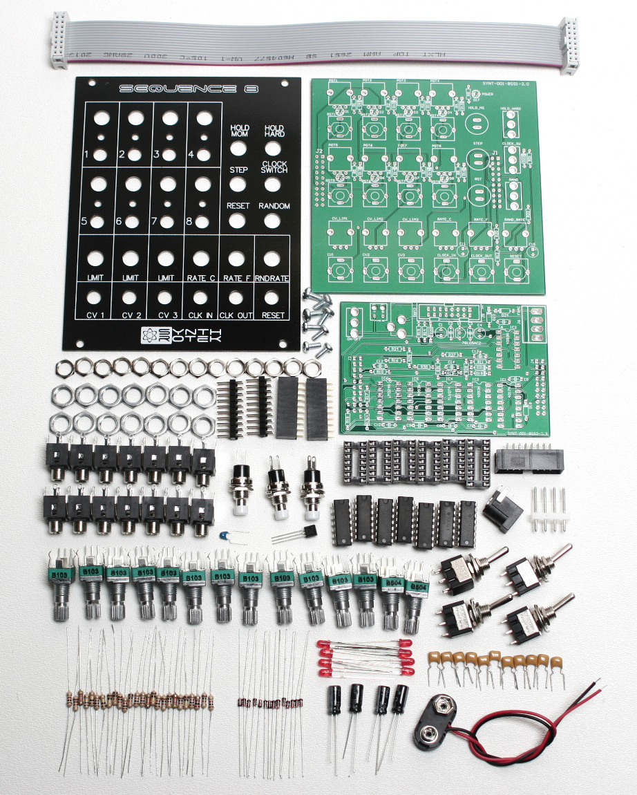
Check your kit against the BOM and verify that all components are present – if anything is missing we will ship it to you free of charge.
Attention: Changes may occur after the Assembly Instructions are created and the photos may not reflect those changes. Always use the BOM to verify the placement of components.
Resistors & Diodes
Begin by soldering all resistors and diodes into place, taking care to align the stripe on the diodes with the corresponding markings on the silkscreen. Resistors are non-polar components and may be inserted in any orientation.
Sockets, Capacitors, & Voltage Regulator
Next install the sockets, capacitors, and voltage regulator. Electrolytic capacitors are polar components and the longer leads must be inserted through the positive via, but ceramic capacitors may be installed in any orientation. Align the flat edge on the voltage regulator with the corresponding marking on the silkscreen.
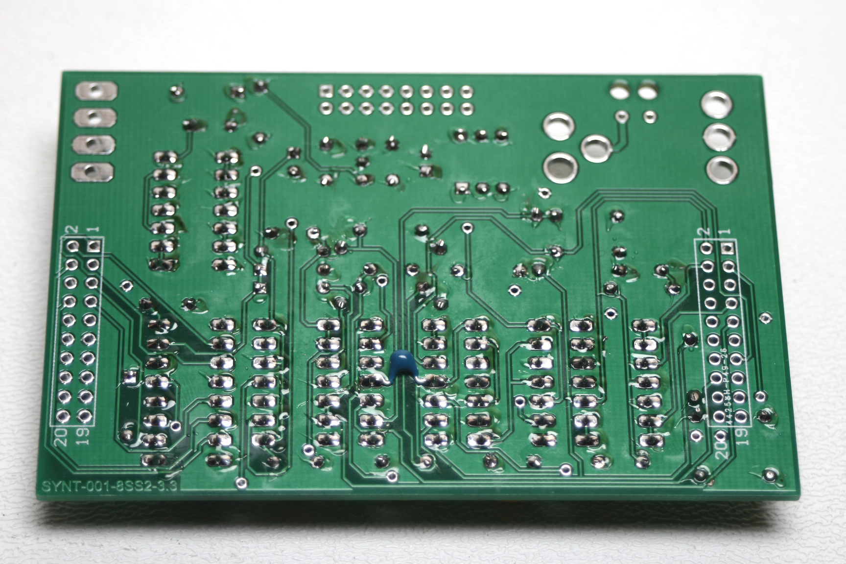
Solder the 220nF capacitor between pins 4 and 11 of IC4 (TLV274) on the back side of the logic board using the above photo for reference orientation.
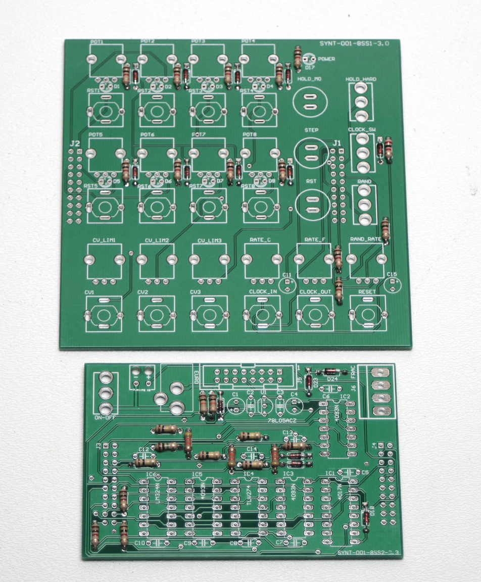
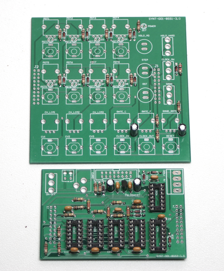
20 Pin Headers
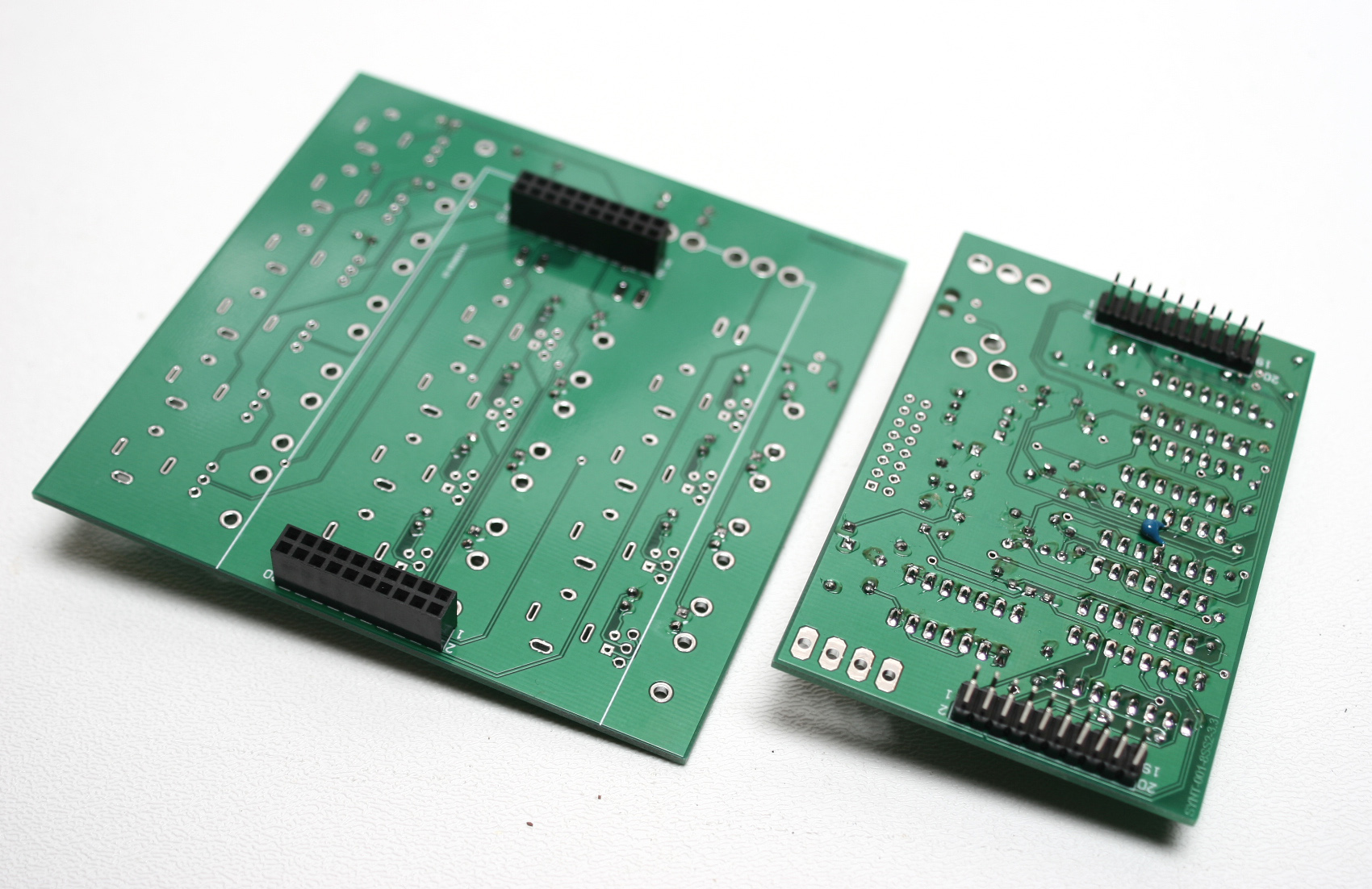
Insert the 20 pin male headers into the logic board PCB and 20 pin female headers into the control board PCB. Seat the shorter side of the pins into the PCB and then solder into place.
Power Connector(s)
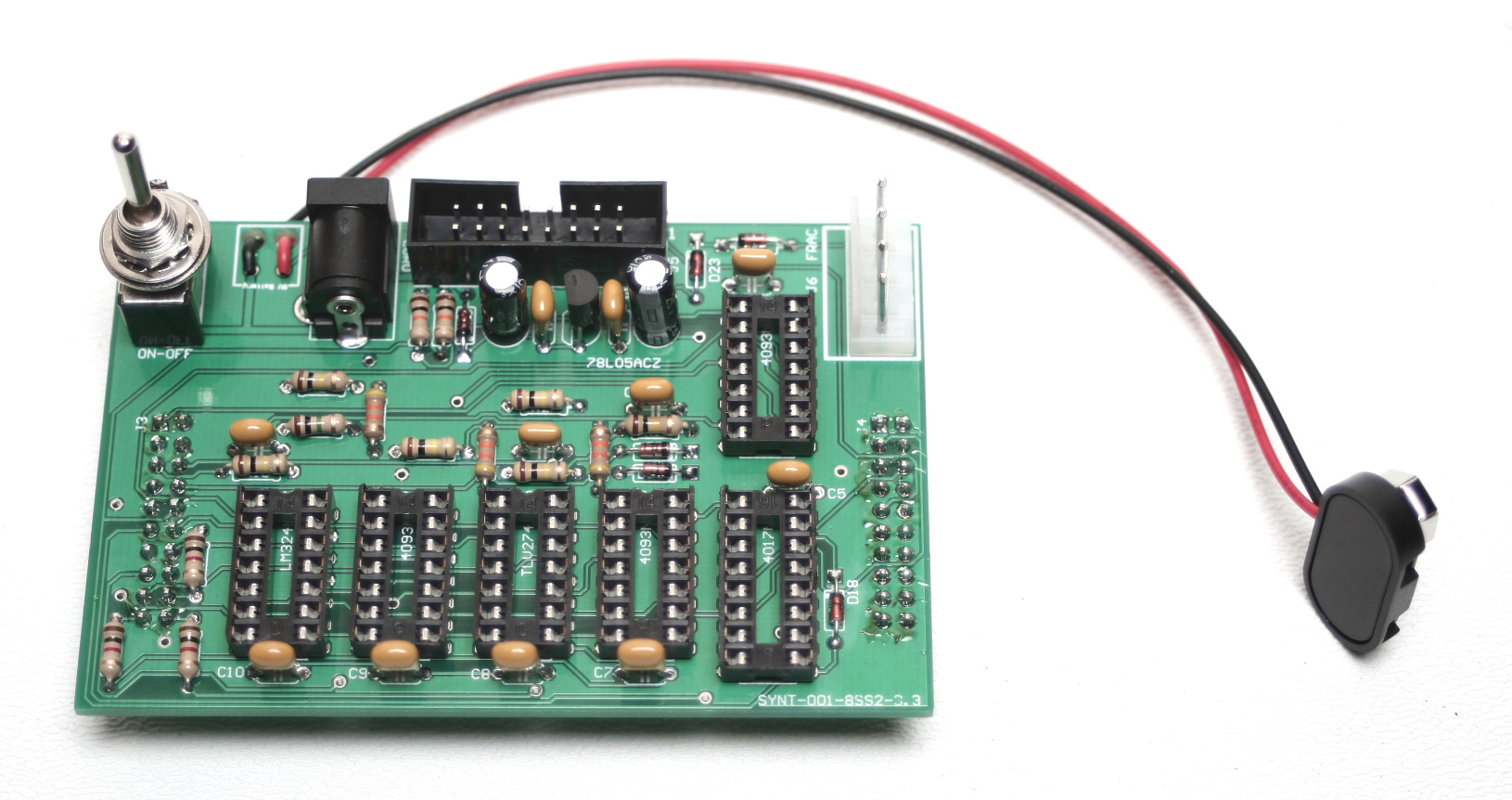
Insert your power connector of choice (Eurorack 16-pin male shrouded keyed header, 4-Pin FRAC header, 2.1mm right angle DC jack, or 9V battery clip) and solder into place on the logic board – all four connectors are shown above for reference. The ON/OFF switch is only necessary for 9V/2.1mm D/C jack users. Now that you are finished soldering all of the components onto the logic board, you may insert all of the ICs into their respective sockets.
Potentiometers, Jacks, LEDs, & Front Panel
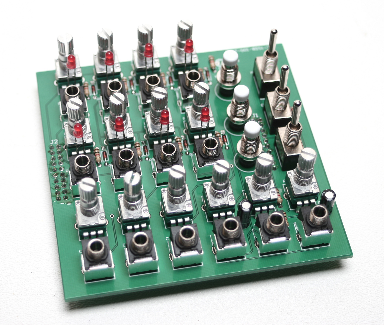
Next remove *all* nuts/washers from the potentiometers and switches and insert them into the control along with the audio jacks. You will only need the nuts – and only one nut from each SPDT switch – so dispose of or use the washers and extra nuts as you see fit. Remove the nubs/tabs from the potentiometers prior to installation:

Don’t forget to cut the nubs on the potentiometers as necessary.
At this point all pots, switches, jacks, and LEDs should be seated (but not soldered) into the control board PCB. Lift the board off of your workspace, push the LEDs through the PCB until they are flush with the board, and carefully place the front panel over the unsoldered components. Screw the nuts into place, taking care to avoid undue component stress from overtightening. “Finger tight” or tightened to the point of slight resistance is sufficient. After you have fastened all of the components to the front panel, you’ll want to guide the LEDs into their respective holes. Make sure that the long leg (anode) goes into the square via.
Now you may solder all components on the control board into place. By seating all of the components to the faceplate before soldering, you are able to keep the faceplate and control board PCB from flexing.
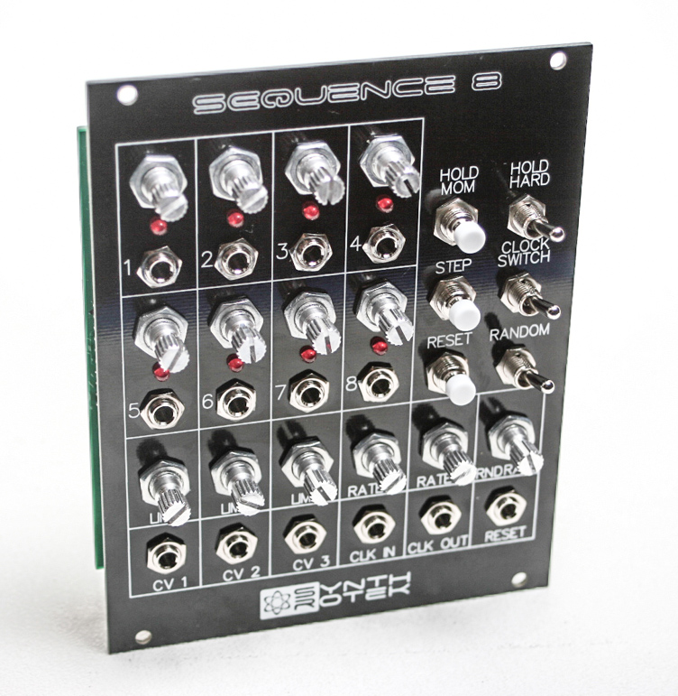
All that is left is to connect the control board PCB and logic board PCB together – make sure to match the 1/2 & 19/20 pin markings on the silkscreens. Now you are ready to test your circuit and get sequencing!
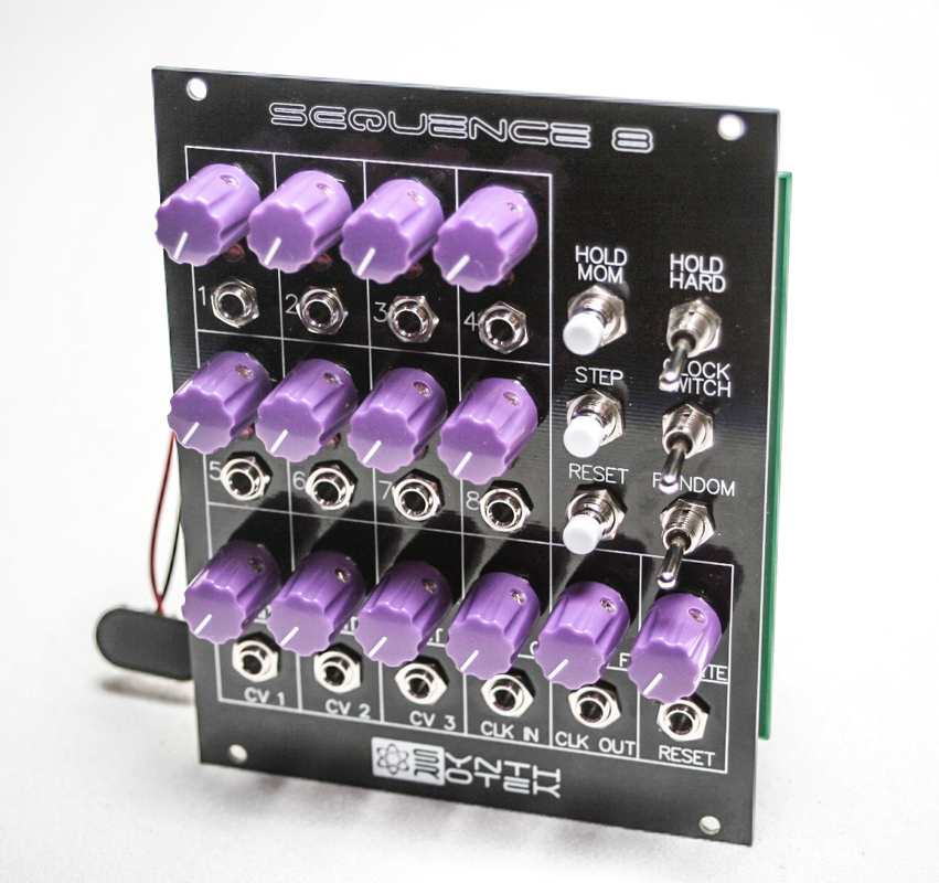
Completed Project
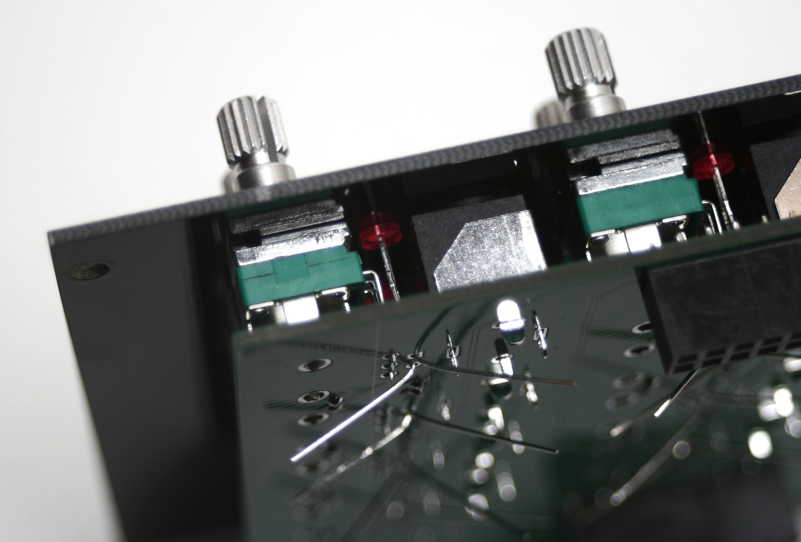
Eurorack & Frac Users: brace the logic board when inserting 16 pin IDC or 4 pin Molex power cables – the board will flex when inserting the cable due to the socketed headers that connect the control board and logic board.
Testing Procedures
Before you start this test, make sure that all knobs on the Sequence 8 have been rotated fully counter clockwise and that all 3 toggle switches (Hold Hard, Clock Swich, Random) are in the down position.
—TESTING CV OUTPUTS—
When you first turn on the Sequence 8 it should be running on its internal clock. Let’s make sure that all 3 CV Outputs are working correctly. Begin by plugging in a cable into the Sequence 8’s CV 1 Output and plug the other end of the cable into the 1V/Oct Input on an Oscillator, and make sure to monitor the output of the oscillator.
Since all 8 of the sequence knobs are rotated fully counter clockwise and the CV 1 input is set fully counter clockwise, you should get a stable tone out of your Oscillator. Rotate Step 1’s knob fully clockwise and leave the CV 1 attenuator set fully counter clockwise. You should still get a stable tone out of your Oscillator when it passes the voltage for Stage 1. If the Oscillator changes pitch even though the CV 1 Attenuator is turned down all the way, then you might have built the Sequence 8 with unleaded solder, which we recommend against doing at the very top of the Assembly Instructions.
Flip the HOLD HARD switch into the “UP” position and press the red STEP switch to reach Step 1 on the Sequence 8. From your Oscillators resting position you should notice the pitch change 5 octaves as you rotate the CV 1 Attenuator from fully counter clockwise to fully clockwise.
Repeat these same steps for the Sequence 8’s CV 2 and CV 3 Outputs. While you are plugged into the CV 3 Output, press the STEP button to advance to Step 2. Rotate the Step 2 knob clockwise and confirm that it is also going to 5V. Do this same thing for Steps 3 through 8.
You should be able to confirm that all 8 steps can pass a minimum of 0 volts to a maximum of 5 volts and that all 3 CV Output Attenuators are working correctly. Now Flip the HOLD HARD switch into the “DOWN” position.
—TESTING CLOCK IN / CLOCK OUT—
TESTING INTERNAL CLOCK:
Slowly rotate the RATE C (Course) knob until you notice the pattern going quite fast. Now rotate the RATE F (Fine) knob from fully counter clockwise to clockwise. You should notice that the RATE F knob will make fine adjustments to the internal clock and that the RATE C knob makes course adjustments. When both knobs are rotated fully, you should see all 8 LEDS for all 8 steps light up. It doesn’t go quite into audio range, but it does go pretty fast. Now hold down the red HOLD MOM (Hold Momentary) switch and you should notice (via the LEDs on the front panel) the sequence has stopped at one of the 8 steps.
TESTING EXTERNAL CLOCK:
Flip the CLOCK SWITCH into the “UP” position. Using an external clock source, the Sequence 8 can go a bit into audio range (somewhere above 1kHz). Test this by plugging in an external clock source or square wave from an LFO and run it into the CLK IN jack on the Sequence 8. Monitor the CLK OUT and turn the LFO /Oscillator / Clock Generator up quite high as you should hear an audio pitch. Now monitor one of the CV Outputs and make sure its Attenuator is set fully clockwise. Set some step knobs up the right way and you get some crude waveshaping sounds! Now flip the CLOCK SWITCH into the “DOWN” position.
TESTING RANDOM:
While the Sequence 8 is running on its internal clock, flip the RANDOM switch into the “UP” position. Slowly rotate the RNDRATE (Random Rate) knob clockwise until you will notice the (via the LEDs on the front panel) the sequence start to move around randomly. This random behavior acts subtly at lower settings and will great faster as the knob is rotated clockwise. NOTE: This does not effect the CLOCK OUT. Now flip the RANDOM switch to the “DOWN” position.
TESTING RESET:
While the Sequence 8 is running on its internal clock, press the red RESET switch and you should notice the sequence resetting back to Step 1.
Now plug in a cable into the RESET output and plug the other end into Step 2’s Reset input. The sequence should be holding on Step 1. When you plug into Step 3’s Reset input, it should be holding on Step 2. Step 4’s Reset input should hold on Step 3. Step 5’s Reset input should hold on Step 4. Step 6’s Reset input should hold on Step 5. Step 7’s input should hold on Step 6. Step 8’s Reset input should hold on Step 7.
-_-
At this point you should be able to confirm that the Sequence 8 is working correctly. If you are having issues with your build take a look at our Troubleshooting Guide. If you’d like to know more about your Sequence 8, we suggest you take a look at the manual. Thanks for choosing Synthrotek!
Why do you specify that this must be assembled using lead solder?
Building with lead solder will insure that the Sequence 8, if built correctly, will function the way it is supposed to.
For whatever reason, the random function on the Sequence 8 displayed odd issues when using lead free solder.
We’re looking into why this is but for now we recommend customers build with leaded solder.
-Zach
For R9, should I leave it empty, or install a wire jumper?
Leave it unpopulated
I assembled it using unleaded solder, and got issues with the clocks and the random function. Do you have an overview of which solder points I should resolder using lead, or do I have to resolder the whole thing?
Hello Frode,
We recommend building it with lead solder to prevent this issue. The specific spots aren’t certain, resoldering it with lead might be problamatic.
To be sure of whats going on with your build, I’d suggest sending a video of the troubles you are having to synthroteksales@gmail.com so I can help you further and be clear to what symptoms your build is having.
Talk to you soon,
In comments from Ben R9 leave empty, but in pic it is populated with 1k res?
Hi Alan,
As per the red colored notice at the top of build guide, follow BOM rather than images; as the images will not reflect any changes made to the build. I’m glad you caught that via comments, though!
-Michael
Do I need to put a jumper or put any LED where the power LED (D17) is meant to go, Also about R9, the resistor to accompany D17 ‘power LED’?
I’m just wondering if these empty places where the components necessary to make the sequencer a ‘stand alone’ model need to have jumpers or must be handled in any special way. When I try to trace the traces, I only become more confused and wonder about It as the confusion stirs up more questions . Thank you!
Hey there, James
You can just leave those places unpopulated and there will be no issues with the build, regardless of power source 🙂
Also, here’s the schematic to give you some clarity; just be mindful that while the circuit is the same, the values should still be referenced from the BOM
http://www.synthrotek.com/wp-content/uploads/2014/04/Sequence_8_Schematic.pdf
Thanks,
Michael
Hi I have a couple questions:
1. I am adding the diodes and I noticed for 1n4148 that there were no locations for D16 & D21, which are listed on the BOM. Also, I did not receive the 2 diodes that may correspond with those locations. Did I miss something?
2. For the 9.1V Zener Diode, is it the one labeled 4739?
Thank you for your response in advance!
Todd
D16 is on the Control Board and D21 is on the Logic Board.
1. If you are missing diodes please contact us at info@synthrotek.com
2. Yes the 9.1 Zener has 4739 printed on it
Thank you,
Steve
I recently built a sequence 8 (using leaded solder) and when i first hooked it up everything worked. The very first time I turned it on, the LED lights were turning on in the correct sequence. I am not sure what happened, but for some reason when I turn on my eurorack the led light stays on the first note. If i press the step button, it goes 2, 3, 4 as expected all the way though 8 and back to 1. If I flip the random switch a random one of the eight LEDs will turn on. When I flip the hold hard switch, the sequence goes in order from step 1 to step 8. The reset button resets the sequence back to one. the rate knob seems to have no effect regardless if I have it fully clockwise or counter clockwise. I do have an oscilloscope and other test equipment but can someone direct me toward what sort of clock signal I should be seeing on what IC pin? Everything appears to be working other than the internal clocking. Thanks!
Hi Richard. I would check out our troubleshooting guide here first:
https://www.synthrotek.com/tech/troubleshooting-your-build/
To be clear, the hard hold switch makes it work correctly? Perhaps I am mistaken
Hi Synthrotek, this is more of a wonder why question. Just finished my second Synthrotek build, Sequence 8, first was a Midi to CV, I knew I was using the Frac connector for my build as it will be in a cabinet with other modules. being on my bench I decided to just use the 9V battery option for test purposes, used a Energizer battery and the voltage read 9.045 VDC , when i went to test nothing was moving, tested the ICs and no voltage at the pins according to the data sheets. Went back and did more investigating and reflowed a couple of questionable solder joints and still nothing. Hooked up the unit with the 12VDC Frac connection , a little over 5 VDC at the ICs and it is sequencing, reacts to the coarse and fine controls, resets does random. What could be the problem using a battery. Has anyone else asked about this problem?
Thanks Steve
Hi Steven thanks for checking in, did you bridge the power switch?
No I did not, was that necessary for the build and I just ignored the Power Switch locations due to the fact I was not using the 2.1 mm DC Jack. I looked over the build guide and did not notice any instruction about the Power Switch bridge. Also I forgot to mention in my first post with the battery only when I plugged into one of the gate jacks the LED did light up,
Hi Steven, you will need to add the switch or bridge it for the battery to work.