


Product Page
Store Page
Assembly Instructions
Bill of Materials
QC Instructions
Capacitor and Resistor Lookup Guide
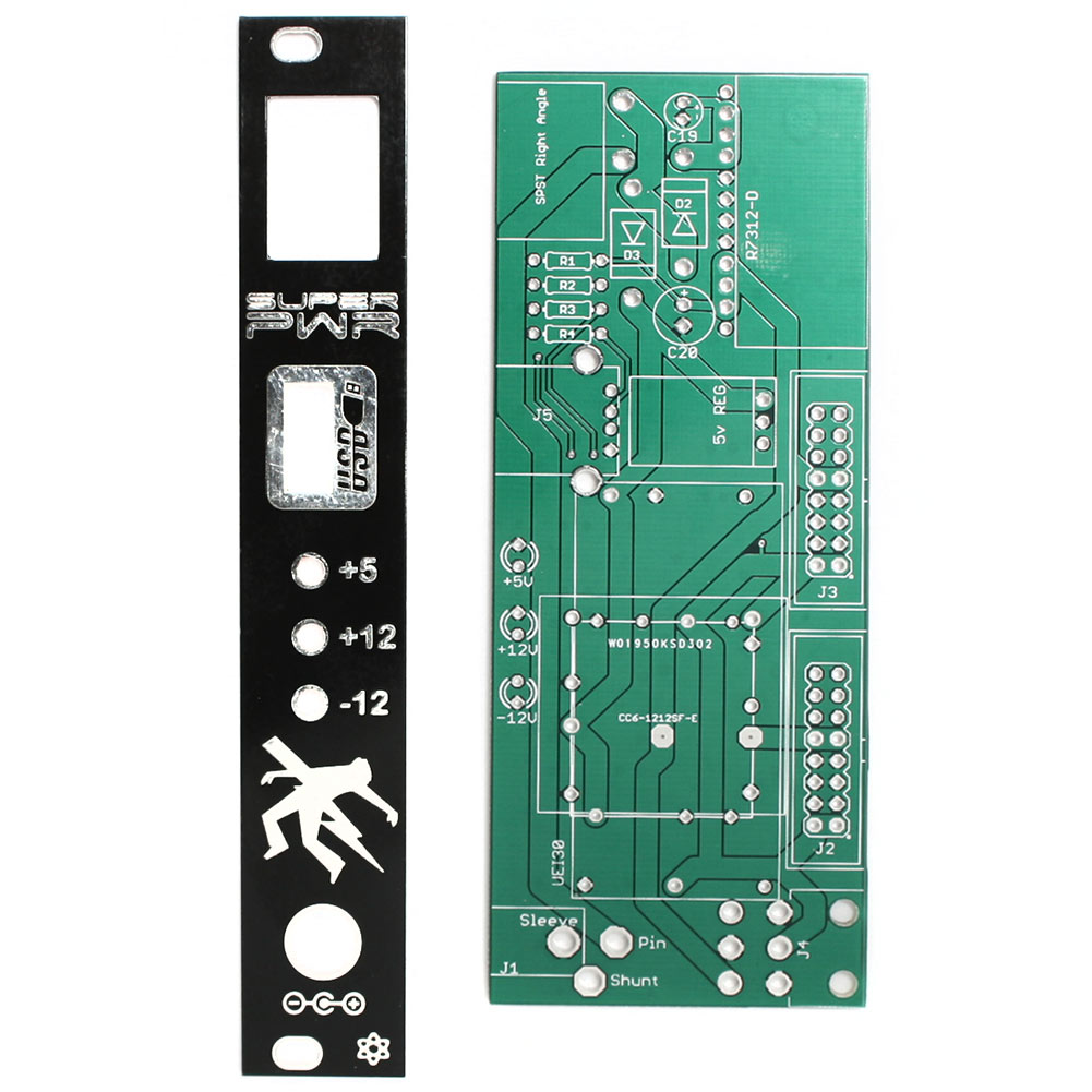
SUPER POWER
Thank you for purchasing the Synthrotek Super Power kit! This is an intermediate build. It is very important to get all the components properly soldered into the PCB in the correct placement. If you feel like you can handle it, please proceed! If not, get some help from a friend with experience or purchase a fully completed unit.
Attention: The molex connector on the Super Power are only for connecting to a distribution board(s). DO NOT connect Super Power to another Case Power, Deluxe Power or Super Power via the molex connector or spade connectors. This WILL damage the power converters and void your warranty.
ATTN: Please follow the BOM and these instructions. Don’t populate from the PCB silkscreen or these instruction pictures alone. Our components may look different from the pictures, so please look over your parts and check the codes first.
LET’S BEGIN
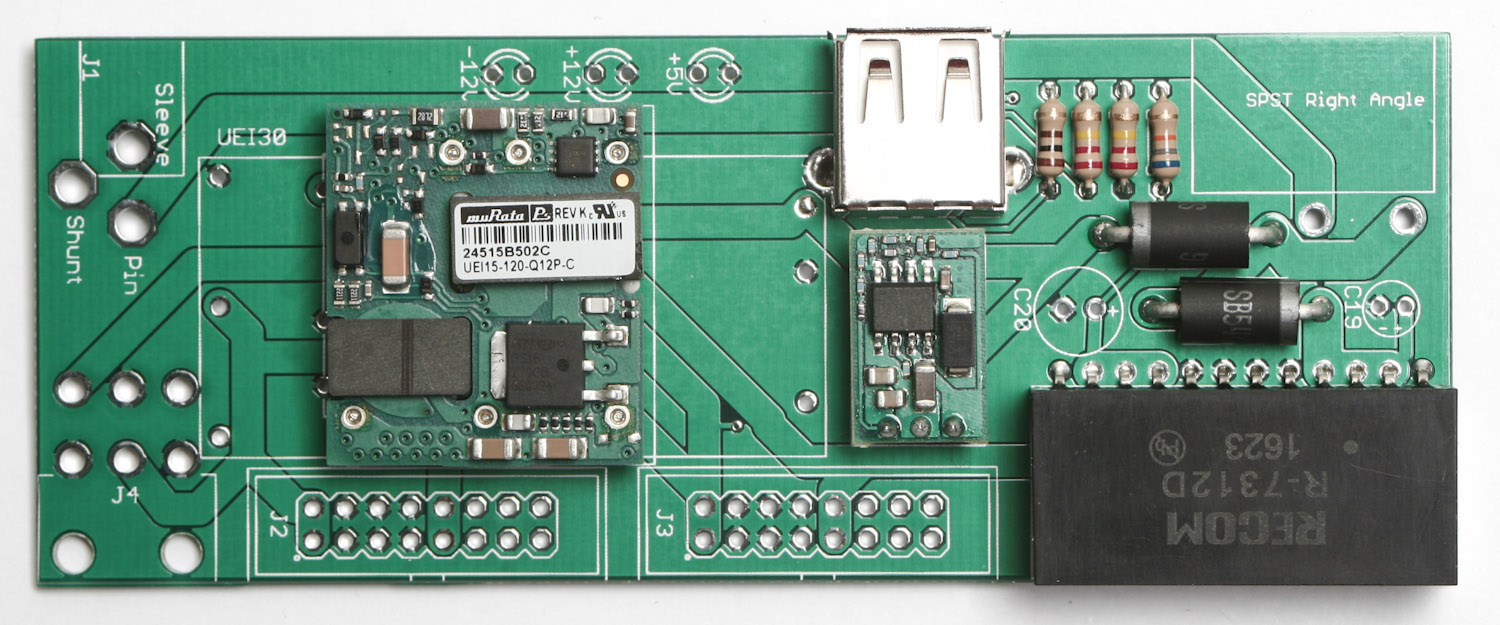
RESISTORS
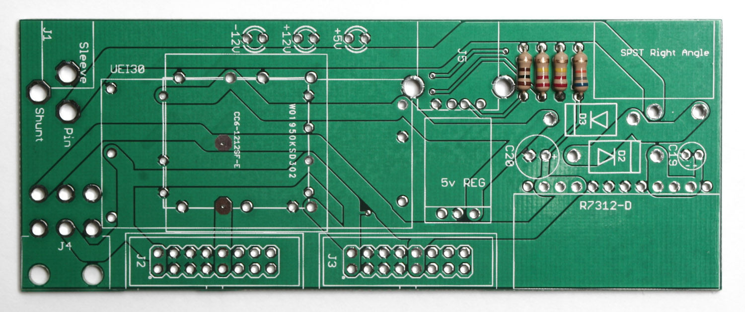
Resistors are not polarized so it doesn’t matter which way they are placed in, but it makes troubleshooting a lot easier if you line up all of the tolerance bands (usually a gold stripe) on the same side. Insert each resistor, matching the value to the proper spot as per the BOM.
Once they are all populated, carefully flip your project over and solder the resistors in place. Clip any excess leads.
DIODES
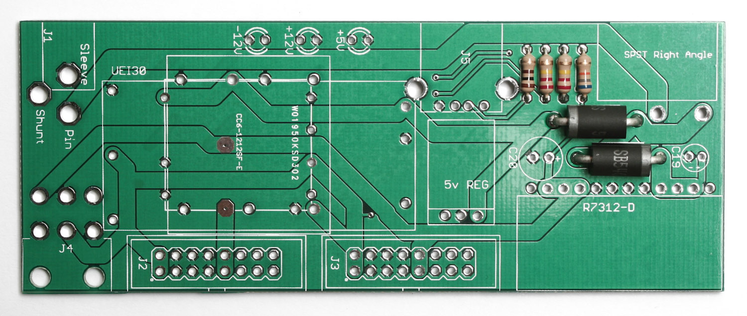
Diodes are polarized, so be careful to align the cathode stripe on the diode with the same cathode stripe on the silkscreen. When these are in place, you can flip the project over onto a hard flat surface, and solder them in place. Clip the excess part of the leads.
+5 VOLTAGE REGULATOR
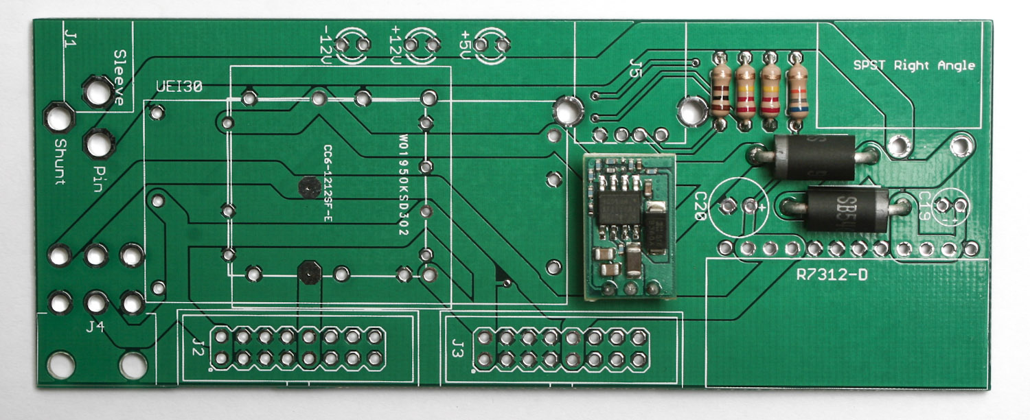
Populate the +5 voltage regulator as shown above and solder.
-12 VOLTAGE CONVERTERS
Case Power has three -12V regulator options:
- TDK for up to 500mA of possible current draw
- MuRata for up to 1.3A of possible current draw
- A larger MuRata for up to 2.5A of possible current draw
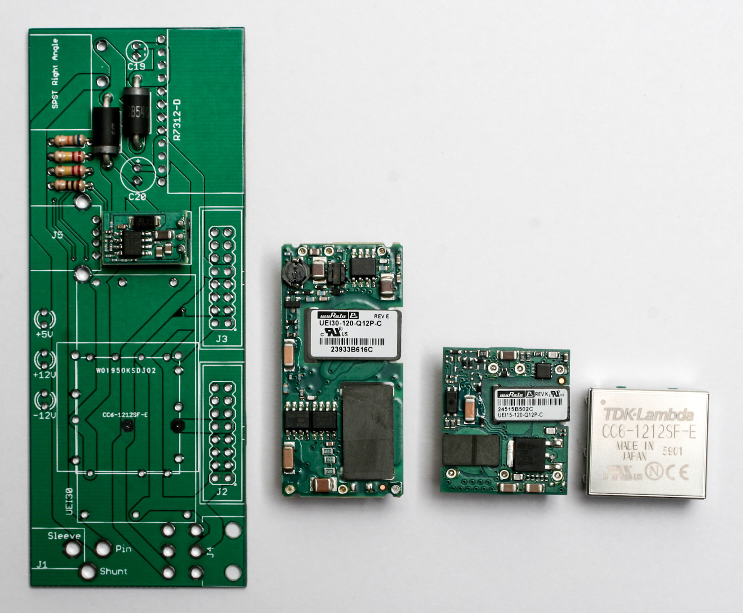
Each converter will fit in the PCB in only one way. For these instructions we will be populating the 1.3A MuRata converter, but rest assured the rest of the instructions will work perfectly with the TDK and the MuRata 2.5A.
USB JACK
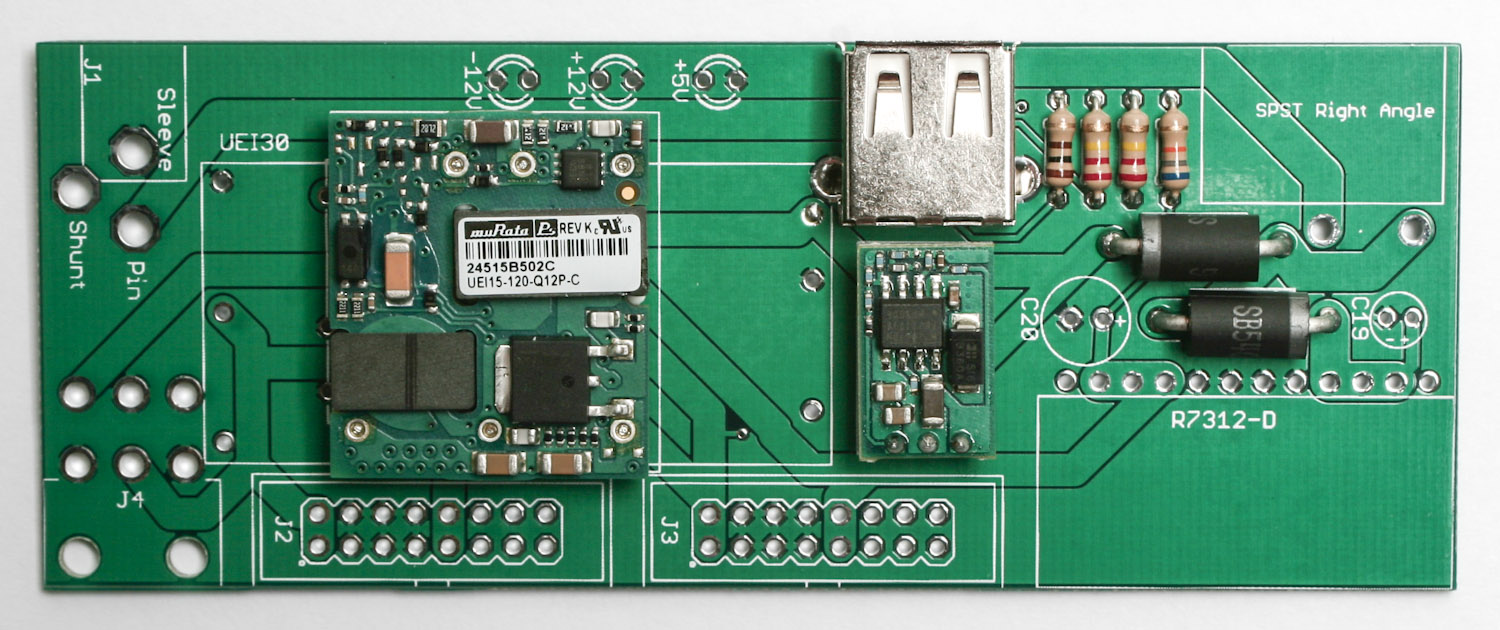
Populate the USB jack as shown above, turn over and solder in place.
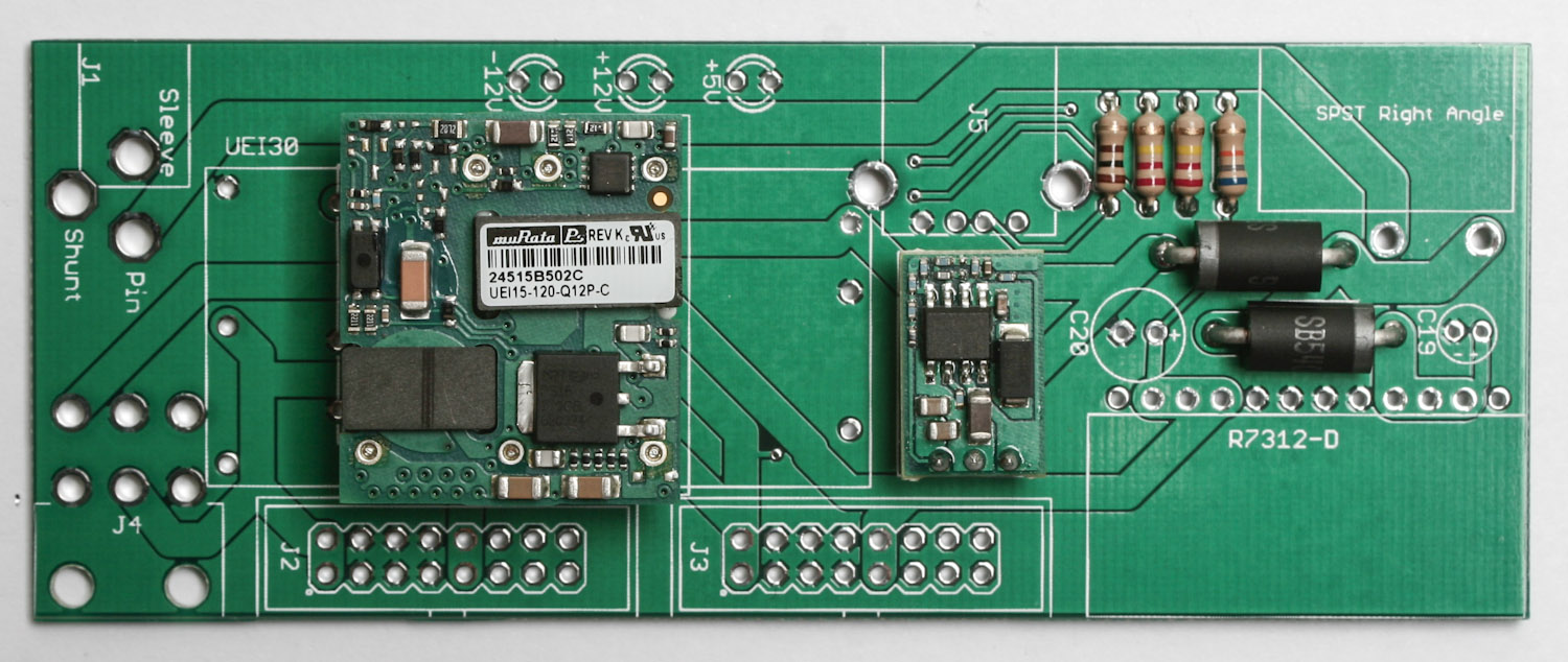
+12 VOLTAGE CONVERTER
OPTIONAL: You can bypass the +12V regulator is you care to use a +12V DC Power Brick. All you need to do is use a short piece of 20-22AWG to jumper the Recom converter as show below. FOR NORMAL INSTALLATION PLEASE IGNORE and skip this step.
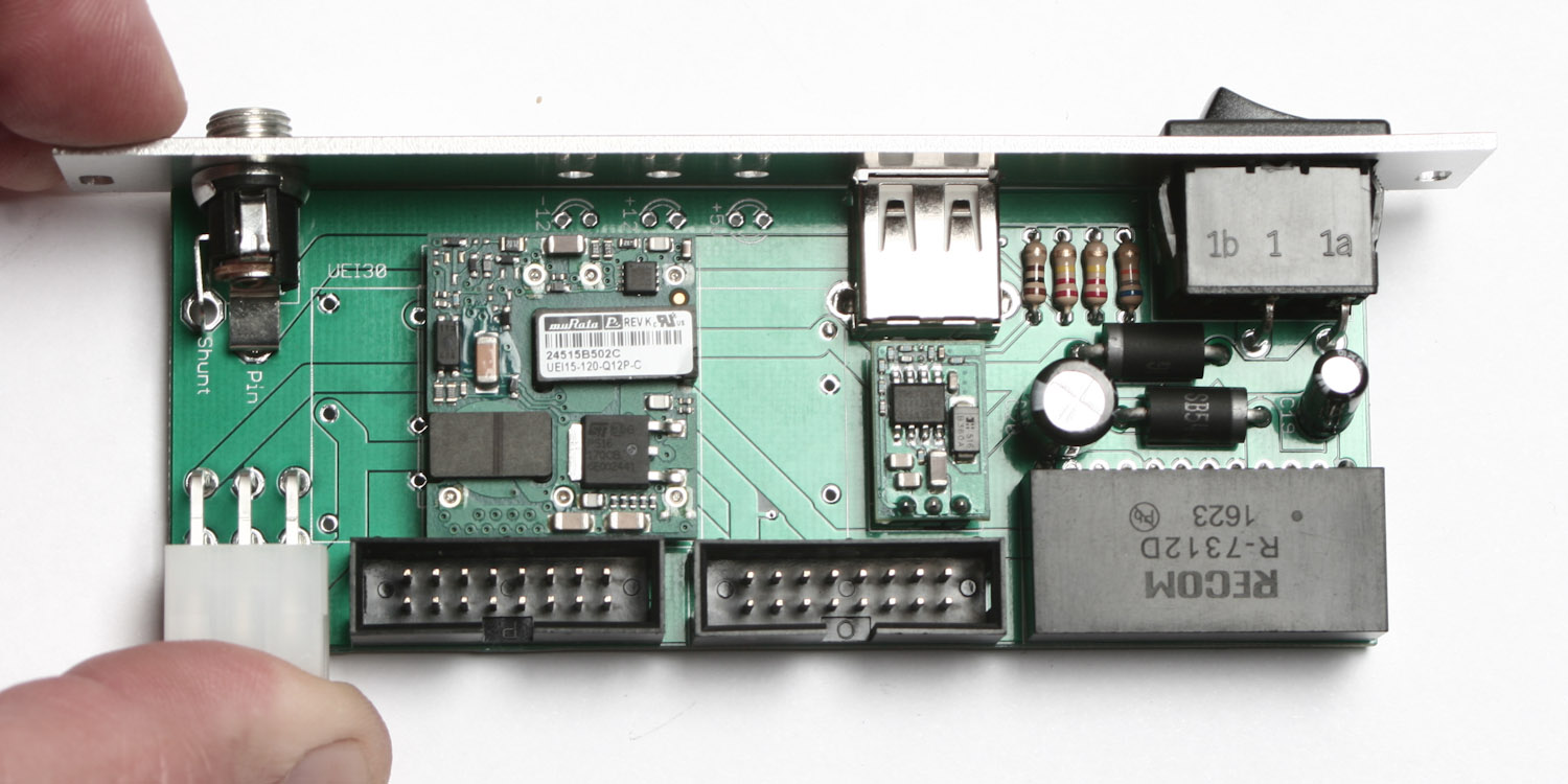
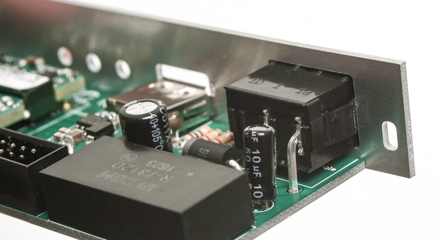
Populate either the RECOM R – 6212D or R – 7312D (they both have the same pin out and will fit onto the board where it reads “R7312-D”) into the PCB as shown above.
Please note: Sometimes the pins on the RECOM regulator need to be bent at an angle. To do this, insert the regulator as shown above, then BEFORE soldering, bend the regulator over until it can sit flush on the board with the pins in the holes. If you solder it in before you bend it, it will not be able to sit flush against the board.
Turn over and solder the converter in place. CAREFULLY use some small wire clippers to trim the leads (DON’T SCRATCH THE SOLDER MASK).
16-PIN EURORACK POWER CONNECTORS
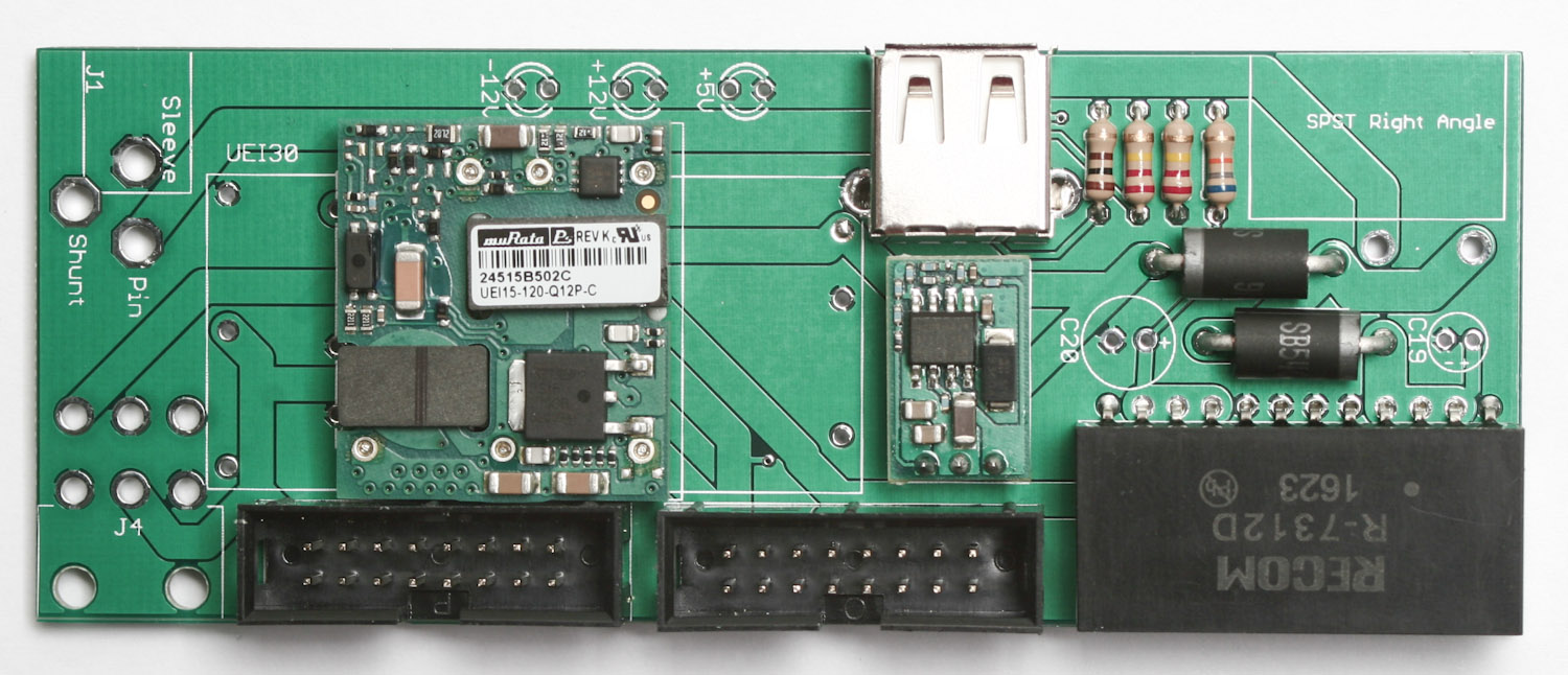
Populate the two Eurorack 16-Pin keyed power connectors as shown above by aligning the keyed notch on the power connectors with the notch on the silk screen on the PCB as shown above. THIS IS VERY IMPORTANT!!! Now use a piece of cardboard or other flat surface to press against the headers and turn over and solder in place.
MOLEX POWER CONNECTOR
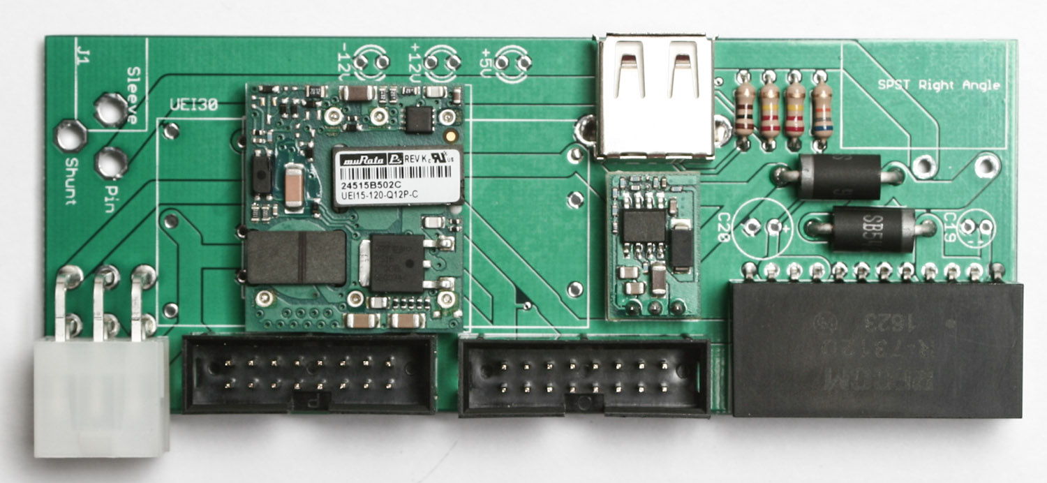
Now populate the MOLEX connector as shown above; turn over and solder in place.
ELECTROLYTIC CAPACITORS
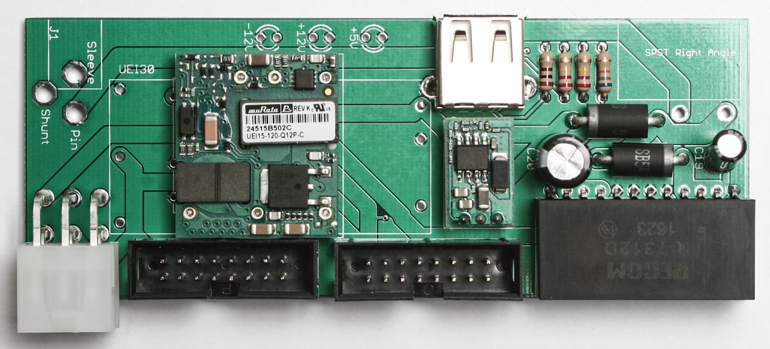
Up next are the electrolytic capacitors. The electrolytic capacitors are polarized, so make sure when populating it that the longer lead goes into the hole with a “+” next to it. Once you have everything in place, go ahead and flip the project over and solder everything into place. Clip the excess leads.
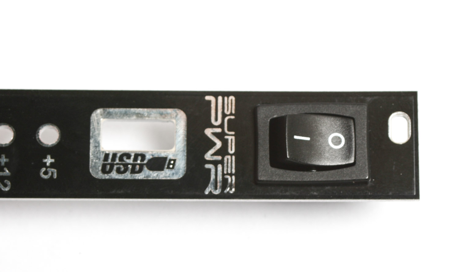
POWER SWITCH
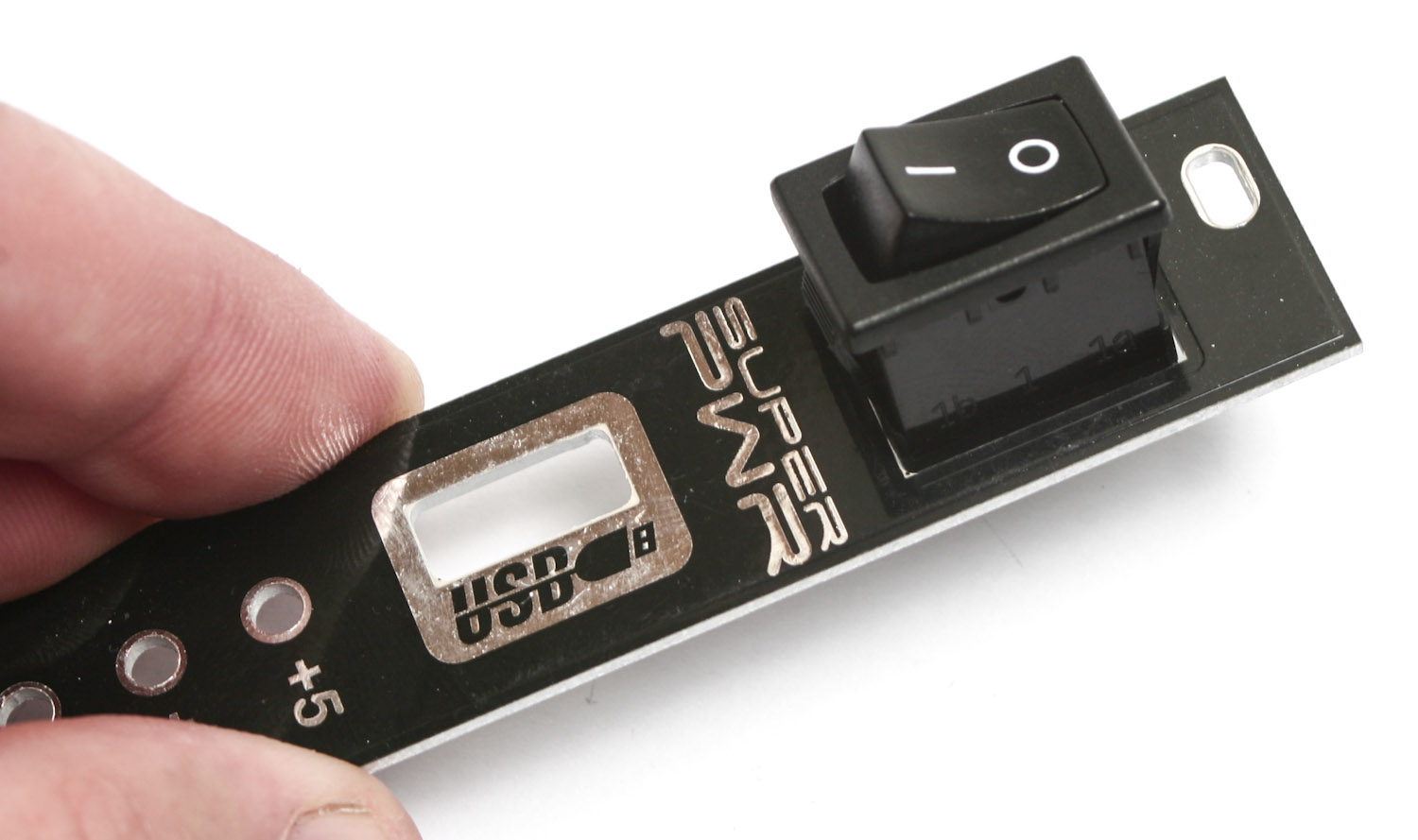
Take the power switch and align it as shown above (make sure that the ‘o’ is toward the top of the panel). Carefully press it through the panel and snap it into place. Be careful as to not bend your panel while doing this.
DC JACK & Panel Alignment
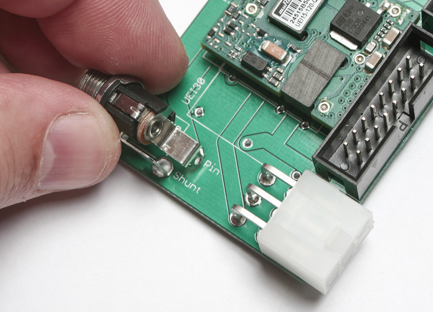
Place the DC jack into the PCB as show above (Don’t solder just yet!).
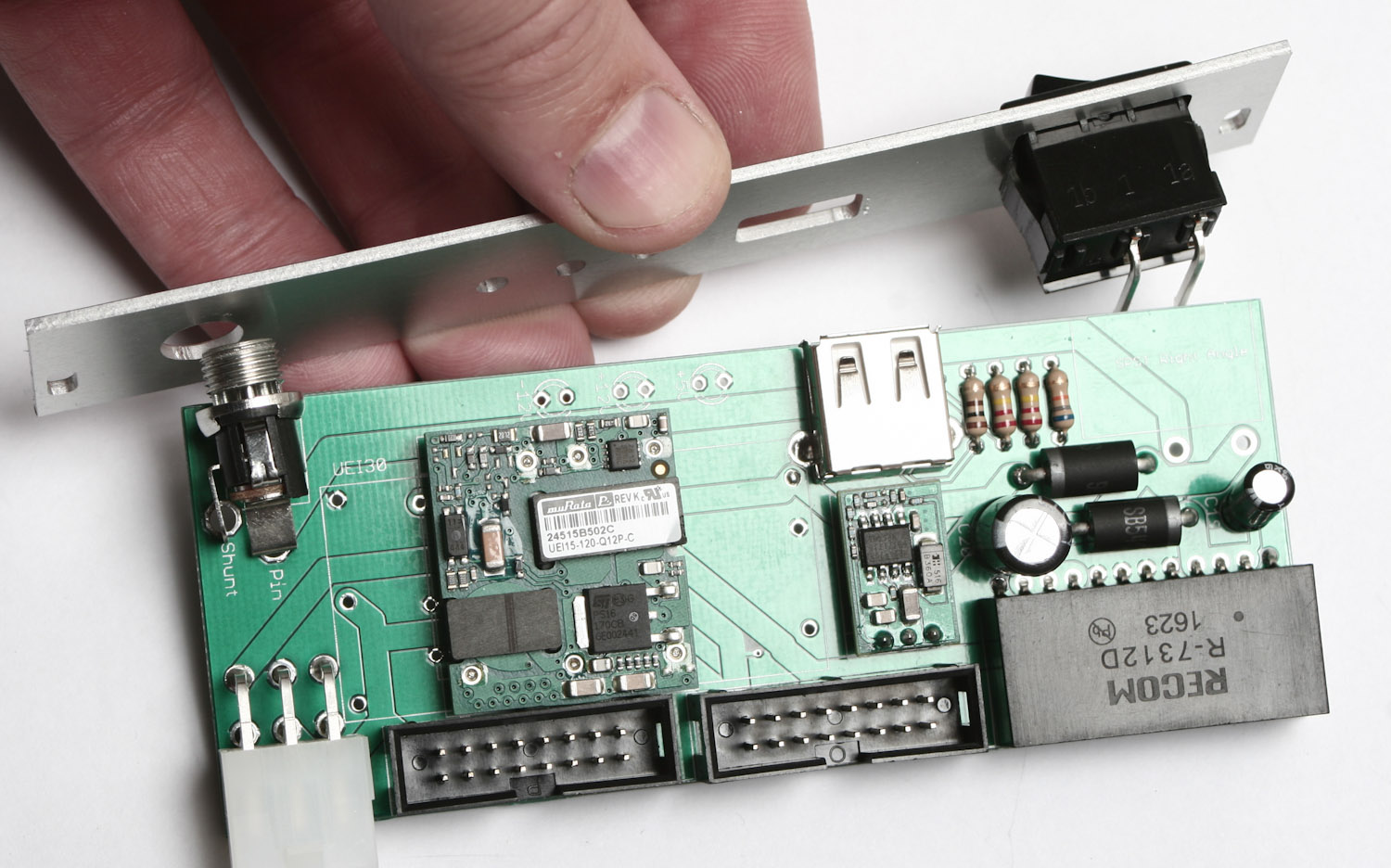
Place the panel onto the PCB as shown above and below.
ATTN: Don’t use the washer that is included with your DC jack. If you do, our locking DC extension cable WILL NOT be able to secure to the DC jack.
Connect the panel to the PCB and place the switch leads in the board as well.
Tighten down the DC Jack Nut as shown above.
Make sure that the switch leads are aligned into the PCB and that the PCB and the Panel are are square with each other. Carefully solder the DC jack and the Switch Leads into place.
RAIL INDICATOR LEDs
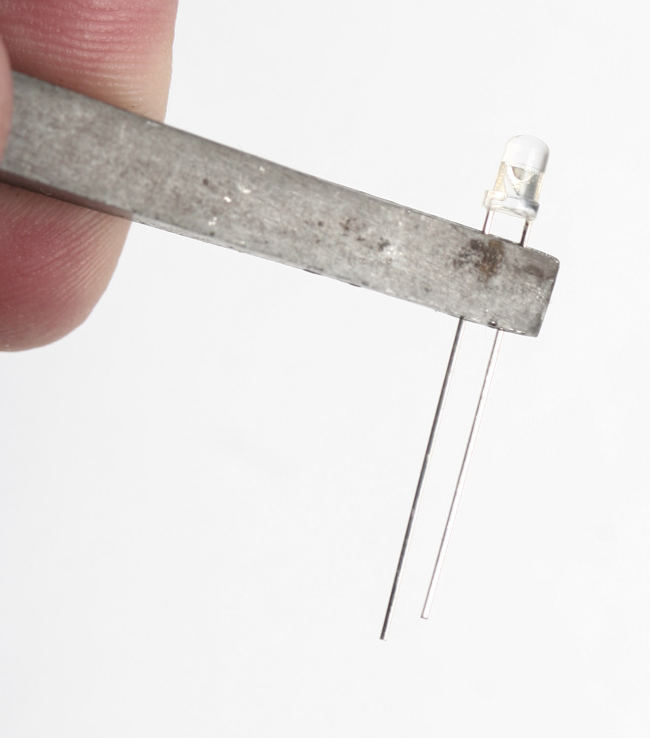
Take a pair of pliers and bend the 3mm LED at a 90 angle as shown above and below. (do this exactly as shown with all LEDs).
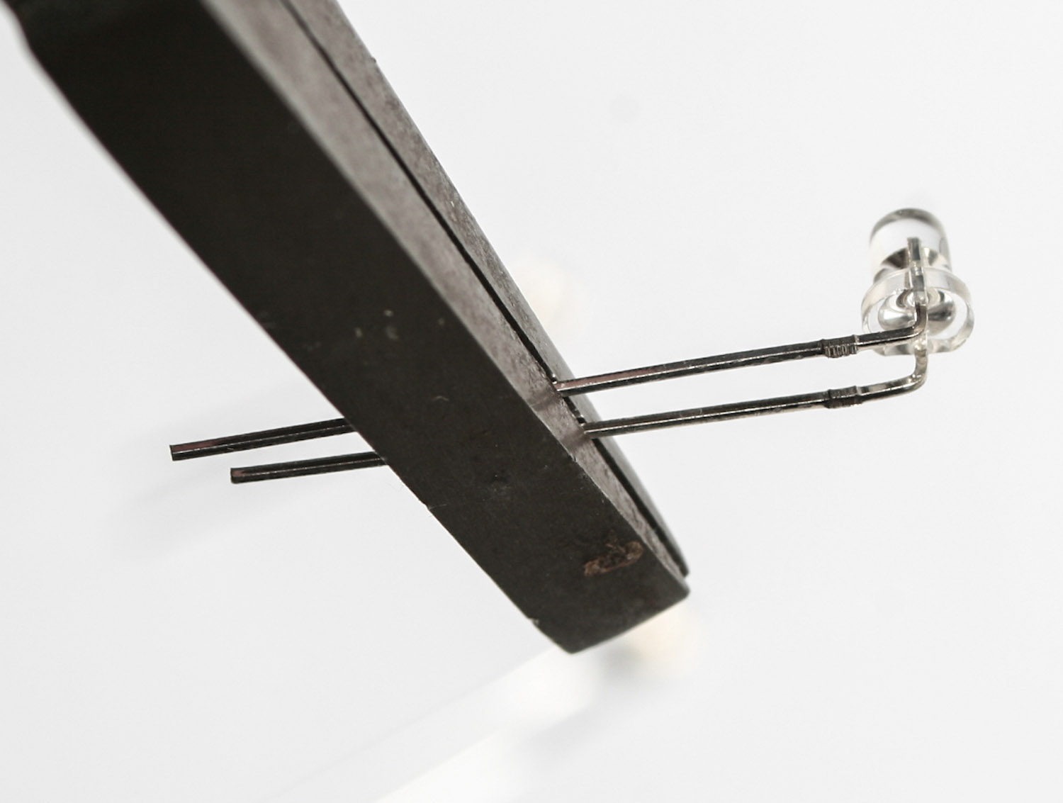
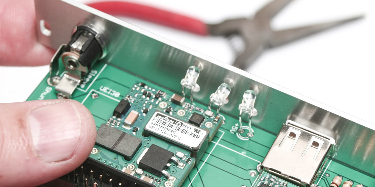
LEDs are polarized and NEED to be placed in the PCB properly. If you bent the LEDs according to the photos above, then you can drop any 3 LEDs into any of the 3 LED positions. The flat side of the LED (and the shorter lead) is the cathode and matches with the flat (opposite side of the rail voltage graphics) side on the silk screen. Push the LEDs into place and have them behind the holes on the panel.
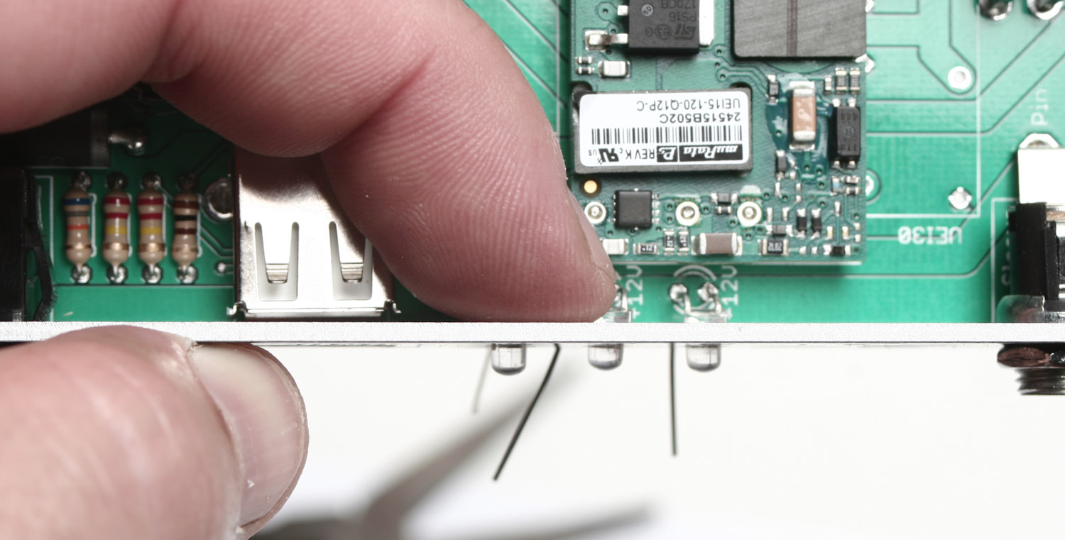
Press the LEDs through the holes all the way, turn board over and solder into place and clip leads.
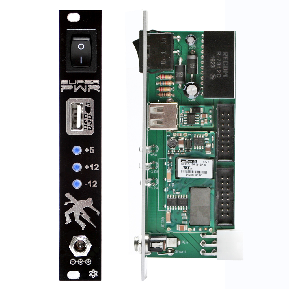
FINAL BUILD
Once you have successfully soldered the LEDs in place it is now time to test your module. If all 3 of your LEDs light up, you should be good to go. It would be wise to also check all of the power rails with a multi-meter before powering modules. Once checked you can connect your flying bus cables to the 16-Pin power connectors or your power distribution board to the Molex connector.
QC Instructions
Now that you have the Super Power built, it’s time to find out if it is working properly.
Follow these instructions if you have either just built the super power and want to check it, or if you have suspicions that your Super Power isn’t working properly.
Tools Needed
- Multimeter
- USB cable and phone, or USB light/device
Since there isn’t a safe way for you to test current draw at home, this test will only make sure that the Super Power is putting out the proper voltages, and that all the jacks are functioning properly.
First up, take a look at your power brick. On the back, it should state that it is between 16 and 19 volts, and center positive. That second one is very important! If you plug in a center negative brick, you may damage your whole system, as you would be feeding positive voltage straight into the ground for everything.
Make sure the switch is in the off position, (the side with the ‘o’ is pressed down), and then plug in your brick to the DC jack at the bottom. If it feels loose, you may have a 2.5mm plug on your brick instead of a 2.1mm plug. It will still work, but you may loose power if you bump your power cable. You can fix this easily with our Locking DC extention cable.
Once your brick is plugged in, turn the module so that the back of the board (the side with nothing on it) is facing you, and the other side is facing the table. Also make sure you are at least an arms length away. We suggest wearing safety glasses just in case, because if something goes wrong with a power supply, there is a chance that it could go violently wrong.
When everything is a safe distance, flip the power switch to the on position. You should see the three LEDs on the front light up. If one or more doesn’t, immediately shut it off, and start diagnosing the issue. Check all your solder joints, and make sure nothing is shorted together.
If all the LEDs turned on, great! That means all the rails are turning on. Next step is to test the jacks.
To test the USB jack, grab your USB device, and plug it in. Simple as that. We recommend a phone or USB light, as they are quick and easy to see if they are getting power from the USB jack.
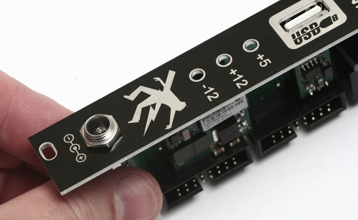
For testing the 16 pin headers, and the Molex connector, please refer to the images below as to what voltages you should find, and what pins you will find them on.
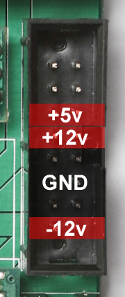
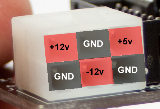
Turn you multimeter on, and make sure it is set to DC voltage, and if it has a limit, set that to 20v.
Following the pictures above, touch the Red probe to each of the pins where the red boxes are, and touch the Black probe to any of the black boxes. You should see your multimeter give the voltage listed in each of the red boxes. It may not be exact, but it should be very close. If it is off by a lot, turn the Super Power off, and start diagnosing for solder bridges. The most common reason for having wrong voltages (either higher or lower) is that there is a solder bridge between two of the rails somewhere.
If all of the voltages look good, then you are ready to plug in your modules, and mount the Super Power in your rack!
If you need further help with issues or diagnosing, check out our Troubleshooting Guide, and if that doesn’t help, you could email us at store@synthrotek.com