


Thank you for purchasing the Synthrotek Stereo Buffered Mult Eurorack kit! This is an intermediate build. It is very important to get all the components properly soldered into the PCB in the correct placement. If you feel like you can handle it, please proceed! If not, get some help from a friend with experience or purchase a fully completed unit.
Please build according to the BOM, and not these instructions or the pictures alone. Some components may have changed since these were written, or we may not be able to get the exact looking components in the pictures.
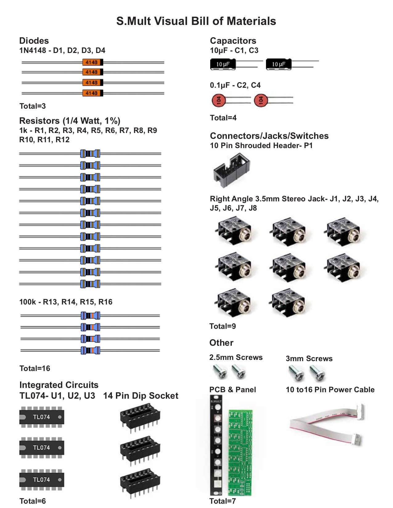
You can find a BOM with Mouser part numbers here.
Diodes
Place your diodes in the PCB as shown below and keep a longish diode lead clipping to use as a jumper. The diodes are polarized, so make sure to populate them with the cathode stripe in the same direction as indicated by the silkscreen.
Once everything is in place, carefully flip your project over and solder the components in place. Clip any excess leads on the bottom of the board.
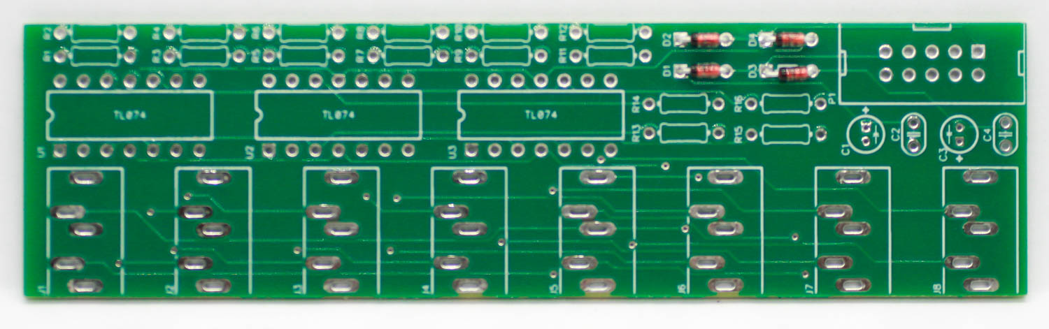
Stereo Buffered Mult Diodes
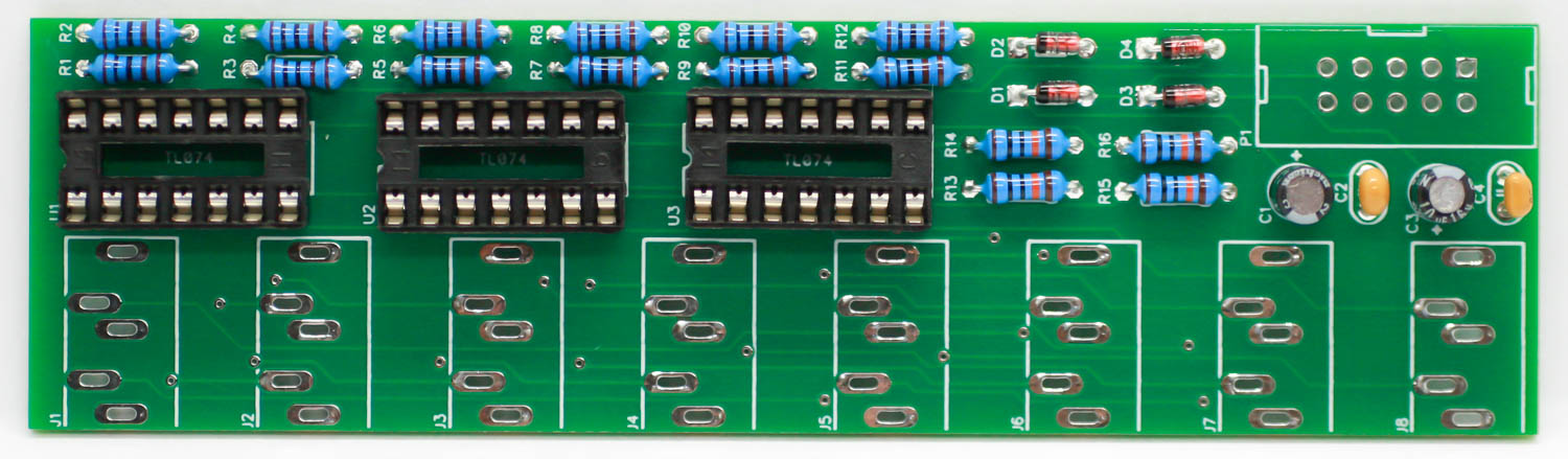
Resistors & IC Sockets
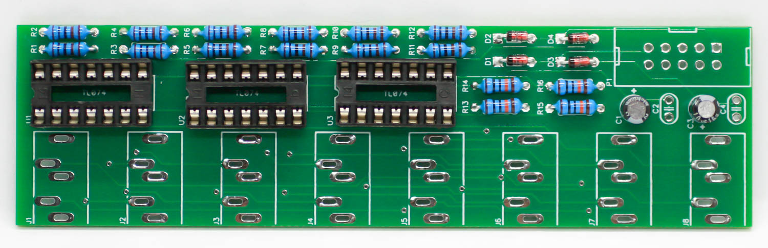
Populate the resistors. Resistors are non-polarized, so it doesn’t matter which direction you put them in the PCB. Once everything is in place, carefully flip your project over and solder the components in place. Clip any excess leads on the bottom of the board. Now place the IC sockets into the PCB by aligning the notch on the socket with the notch on the PCB silkscreen. Carefully turn the board over (hold a piece of cardboard on the sockets while doing this) and solder the pins in place.
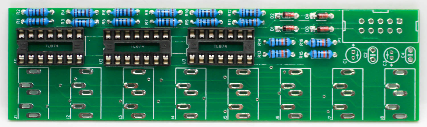
Stereo Buffered Mult IC Sockets & Resistors
Electrolytic Capacitors
The electrolytic capacitors are polarized, so take care! Ensure that the longer leg (the leg that is further from the stripe indicator on the body) goes through the solder pad with the little ‘+’ symbol next to it. Turn over to solder and clip leads.
Stereo Buffered Mult Electrolytic Capacitors
Ceramic Capacitors
The ceramic capacitors are not polarized. Turn over to solder and clip leads.
Stereo Buffered Mult Ceramic Capacitors
Eurorack Power Header
Next up is the keyed shrouded power header. Make sure when populating this that the notch in the header is lined up with the notch designed on the silkscreen. Carefully turn over to solder.
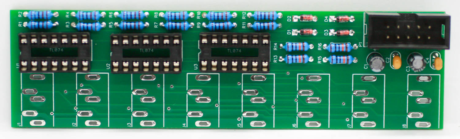
Stereo Buffered Mult Power Header
Jacks and Panel
Place all the stereo jacks into the PCB and carefully place the panel over and hand tighten the jack nuts. CAREFULLY turn over and solder the jacks in place.
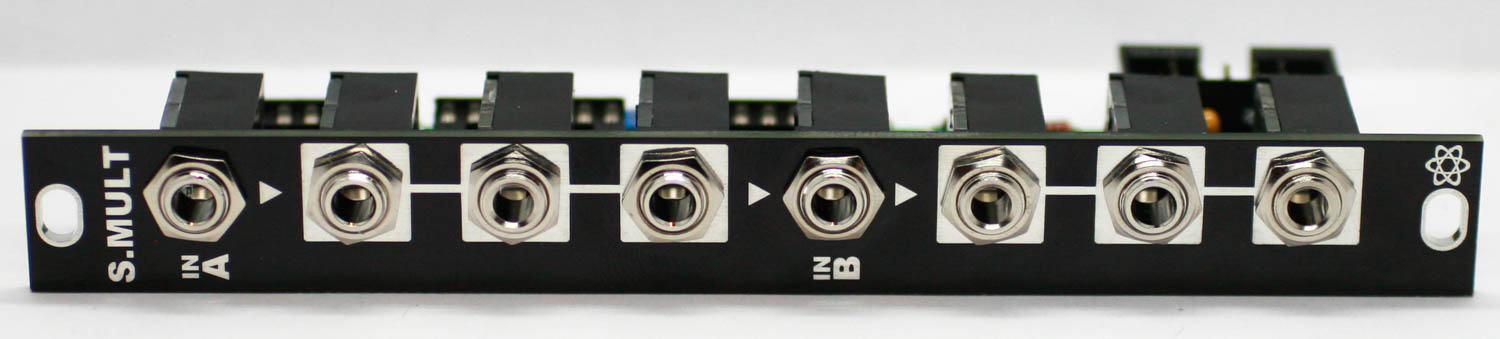
Stereo Buffered Mult Jacks and Panel
Integrated Circuits
Insert the ICs into their sockets. You will need to bend the legs inward a little to make them fit. Match up the notch on the ICs with the notch on the socket and PCB silkscreen. Make sure that all the legs are firmly seated in the socket.
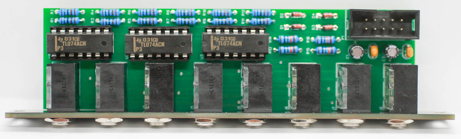
Stereo Buffered Mult IC Placement
Final Project!
Congrats, you are done with your build! You can now plug your module into your power supply and get to it!
Stereo Buffered Multiple