


Important Links
Eurorack Version:
Assembly Instructions
9V Version:
Assembly Instructions
Bill of Materials
Schematic
Capacitor and Resistor Lookup Guide
9-Volt Dirt Filter Assembly Instructions
If your PCB says “2.2” in the corner, use these instructions.
If your PCB says “2.0” in the corner, CLICK HERE.
If you are looking for the Eurorack version of the DIRT filter, CLICK HERE FOR VERSION 2.2
Thank you for purchasing your 9 VOLT DIRT filter Kit, please follow the instructions to ensure that you have a fully functioning unit. ATTN: Please follow the BOM and these instructions and don’t populate from the PCB alone. Also sometimes we cannot get the exact pictured components, so please look over your parts and check the codes first. Let’s get started!
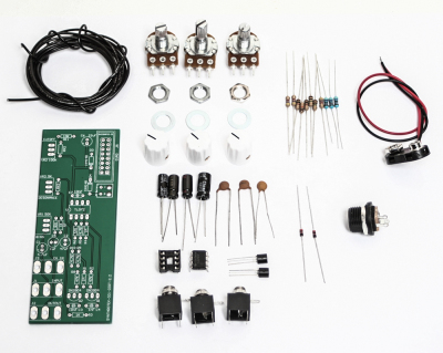
9 Volt DIRT FIlter 2.2
Above is a photo of the 3.5mm jack version of the 9-Volt DIRT filter Kit. You can also buy a version of this kit that comes with 1/4″ jacks.
RESISTORS & DIODES
First, start by populating the resistors and the diode, as shown below, then turn over on a firm surface to solder then clip your leads. Diodes are polarized components so you must match the black stripe on your diodes with the white stripe on the PCB silkscreen.
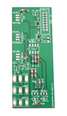
DIRT FIlter 2.2 Resistors and Diodes
CAPACITORS
Place the capacitors in place and solder and clip leads. Make sure you orient the electrolytic capacitors in correctly. The longer lead needs to be inserted into the hole that has the “+” marking near it.
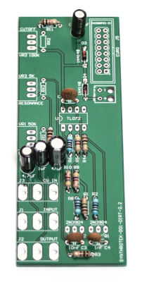
9-Volt DIRT Filter Capacitors
IC SOCKET, IC and TRANSISTORS
Place the IC Socket in place by aligning the notch with the notch graphic on the PCB Silk Screen. Turn over and solder. Now, place the IC in place, make sure you do not bend the pins when pressing down. Next, add the two transistors as shown below by aligning the flat side of the transistor with the flat side of the graphic on the PCB silk screen. Turn over, solder and clip leads.
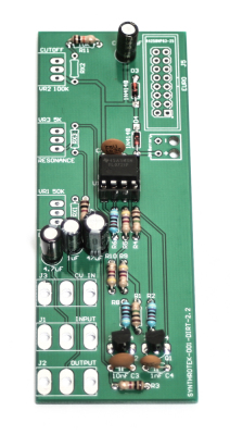
- 9-Volt DIRT filter 2.2 Socket, IC and Transistors
THE INSTRUCTIONS BELOW SHOW THE 2.0 version of the DIRT Filter PCB, but will work perfectly with your 2.2 PCB.
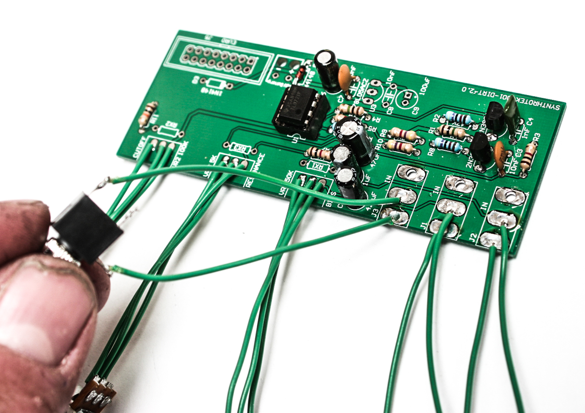
POTENTIOMETERS
First trim the alignment nub off the pots.

Cut the pot nubs
Next, cut 15 wires to your desired length and solder the wires to the pots and PCB as shown below.
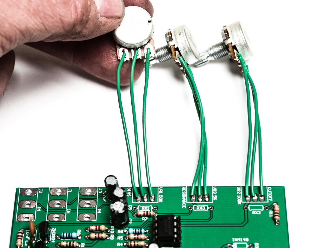
9-Volt DIRT Filter Potentiometers
JACKS
You have two options when purchasing your 9-Volt DIRT filter kit, which are 3.5mm (1/8″) or 1/4″. Follow the diagram that fits your kit.
DIRT Filter 3.5mm Jacks
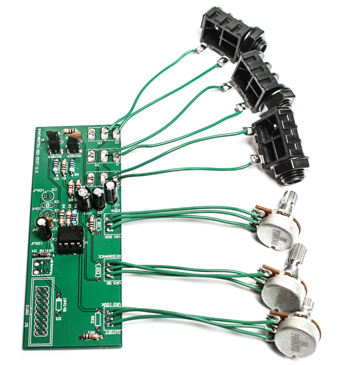
DIRT filter 1/4″ Jacks
DC JACK or 9V BATTERY SNAP
The 9-Volt DIRT filter can be powered by a 9V battery or a DC jack. Follow the instructions below that suit your needs best. Your kit will come with both options.
The 9V battery option is obvious and easy, just connect the red wire through the “+” hole on the PCB silk screen and the black to the “-“. Now solder in place and clip your leads.
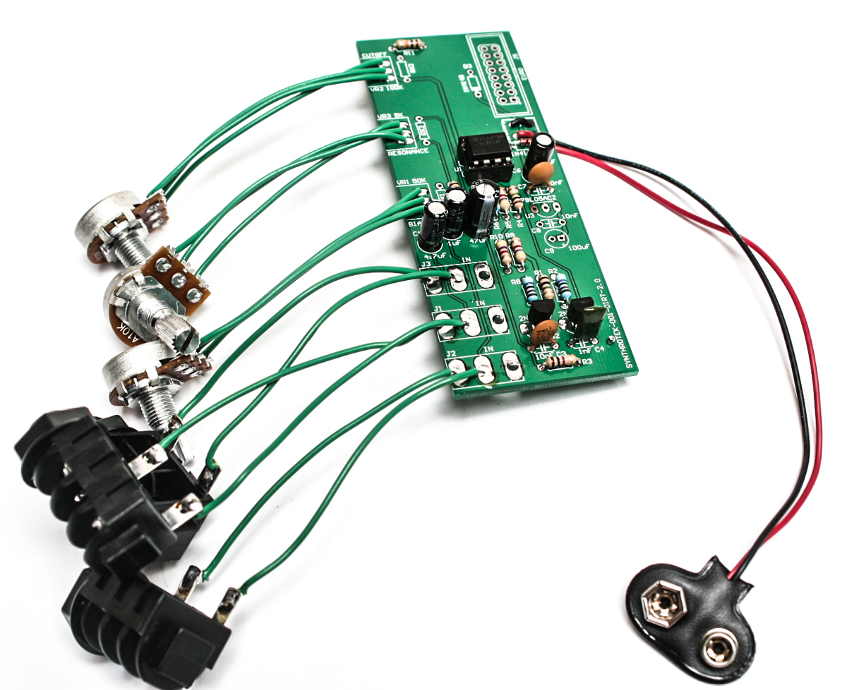
DIRT Filter 9V Battery Snap
When using the DC jack with a 9V CENTER NEGATIVE power adapter (common BOSS or ONE-SPOT style adapter), please follow the instructions below. If using a CENTER POSITIVE, reverse these instructions. You will not have color coded wire in your kit, the colors on here are just to make the instructions easier. Solder two wires as shown below.
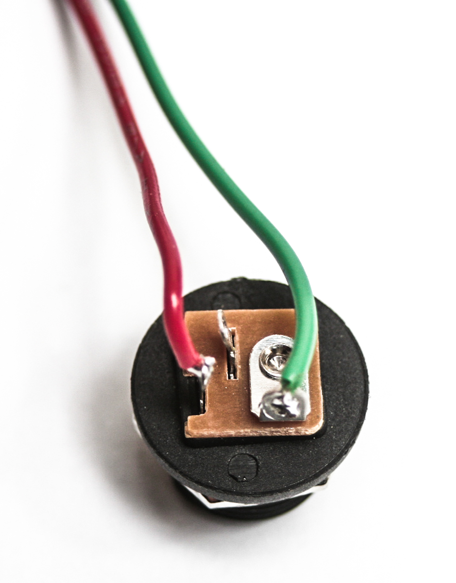
DIRT Filter CENTER NEGATIVE DC Jack wiring
With these colors of wire being used, insert and solder the red wire to the “+” hole on the PCB in the “9V battery” area and the green to the “-“
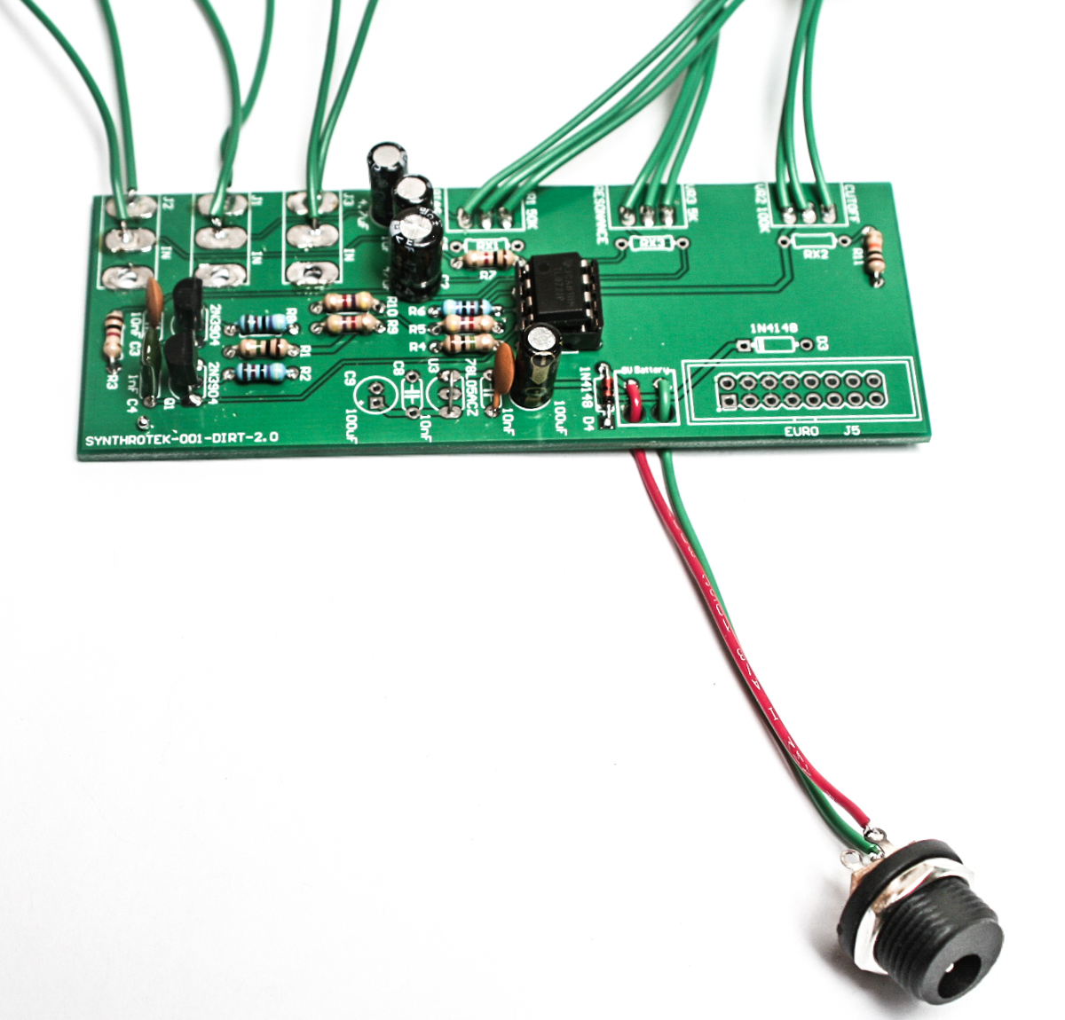
DIRT filter CENTER NEGATIVE DC Jack Wiring #2
CONGRATS! You are now done with your project and can test the unit. If you have any questions or need help debugging, please first refer to our troubleshooting guide BY CLICKING HERE. If this gets you nowhere, please contact us by email for support. Thank you again for purchasing your kit from Synthrotek!
MAKE SOME DIRTY NOISE!
What are the RX1, rx2, and rx3 spots on the pcb for? Could these be used for CV control of the pots?
Hi Roger, those are parallel to the pot pins, you could give it a try, it will change something, but probably not that precise. Adding voltage can work in some cases, but this is not the same as changing resistance.
Hi, just learned resistors are non- polar. sorry first kit!!!
No issue! Hope the rest of the build goes well!