


XFD ASSEMBLY INSTRUCTIONS
Thank you for purchasing the Synthrotek XFD – Eurorack CV controlled crossfader kit. This is an intermediate build. If you feel like you can handle it, please proceed! If not, get some help from a friend with experience or purchase a fully completed unit.
Please build according to the BOM, and not these instructions or the pictures alone. Some components may have changed since these were written, or we may not be able to get the exact components in the pictures.
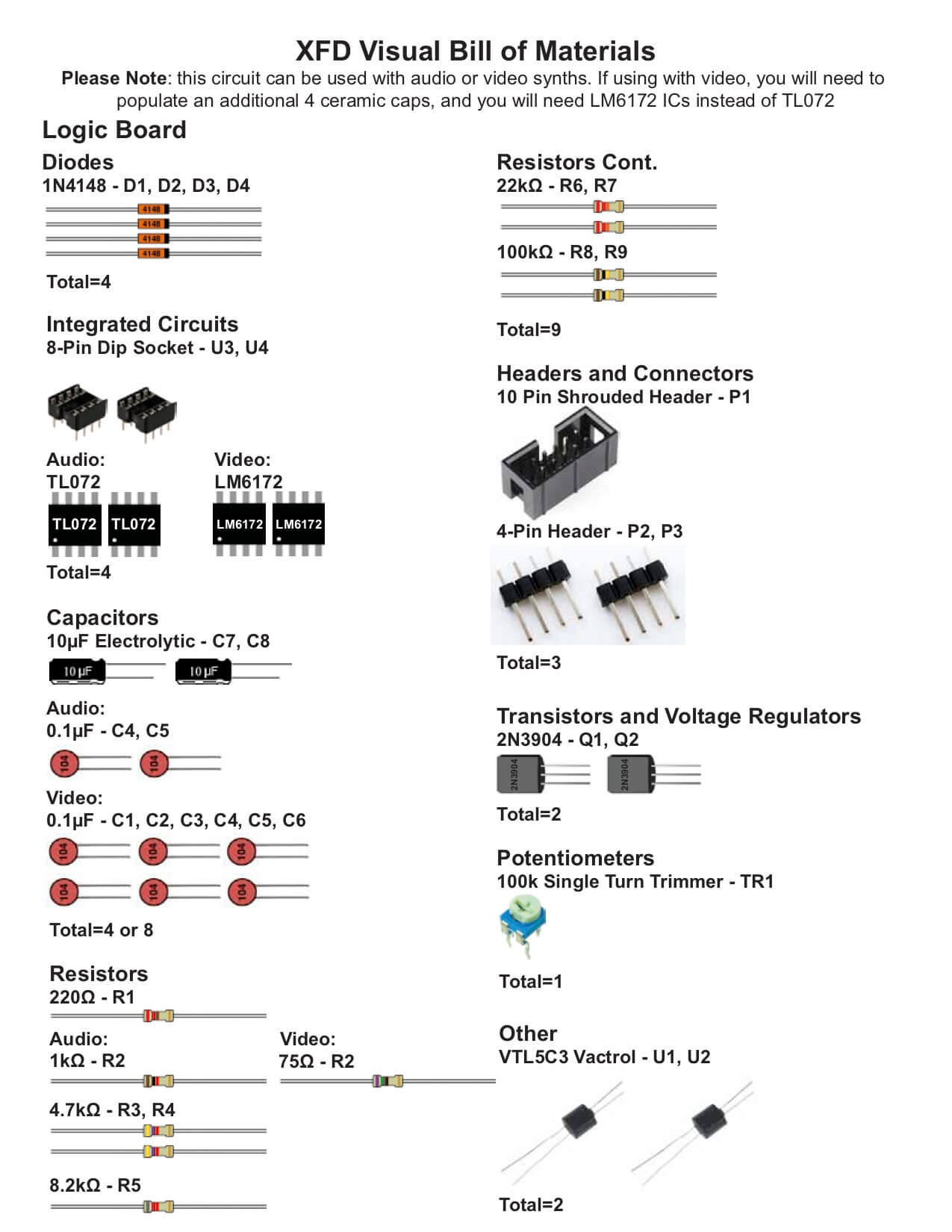
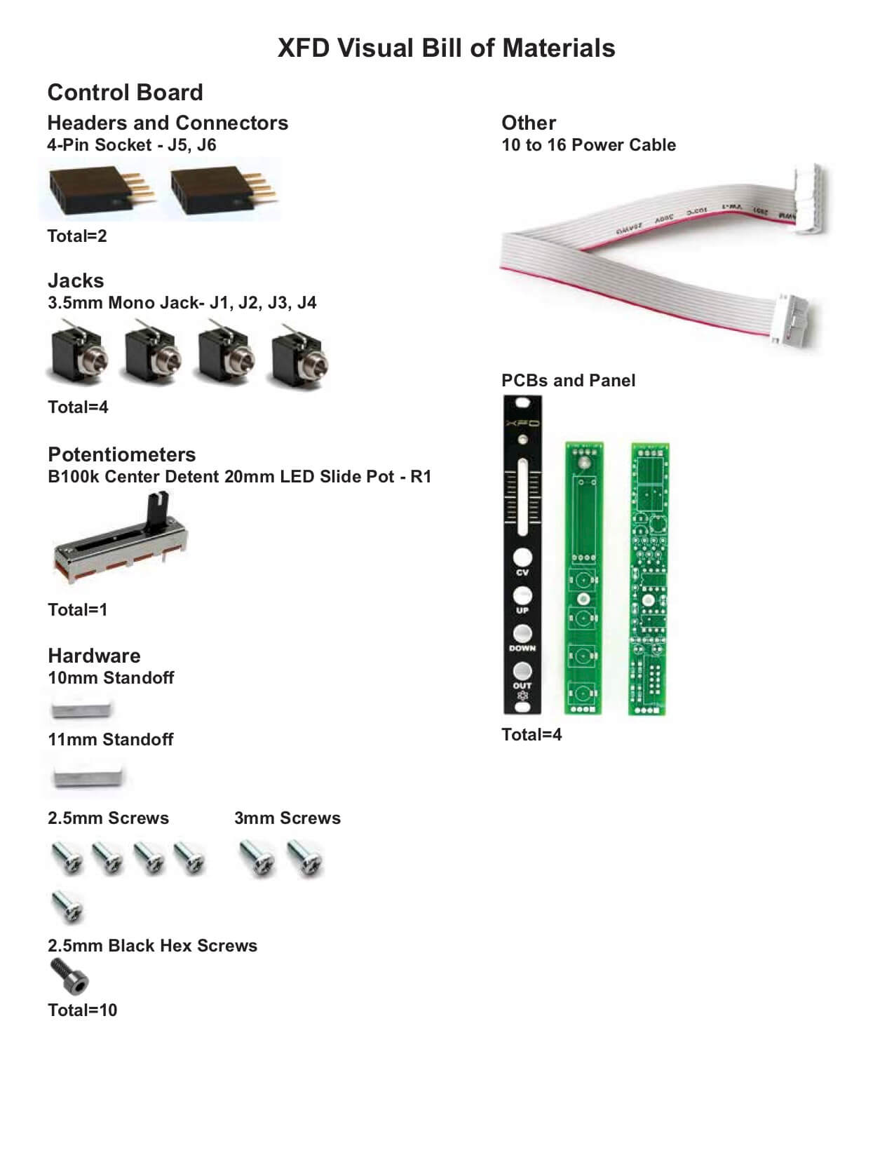 For a list of parts with Mouser part numbers, click here.
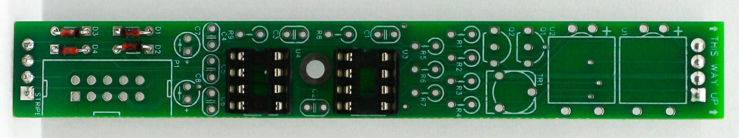
DIODES
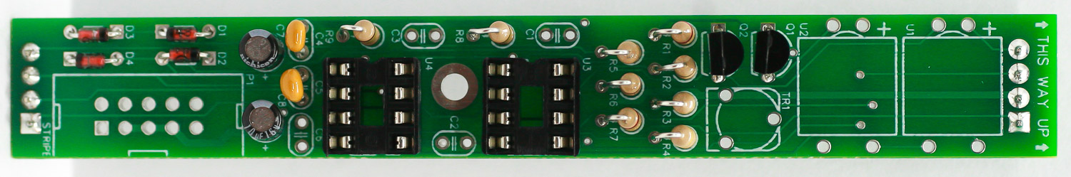
First thing we are going to populate is the diodes. Following the BOM, insert all the diodes into their proper spots, paying attention to the polarity. Diodes are polarized components, and must be populated correctly to function. Make sure to align the cathode stripe on the diode with the cathode marking on the silkscreen.
Then you can flip your project over onto a flat surface and solder all the diodes in place. Then clip the excess leads.
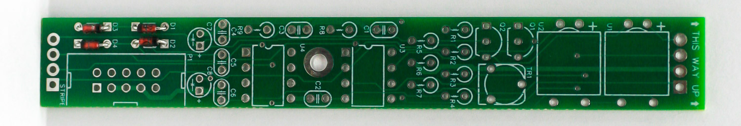
XFD Diodes
LOGIC BOARD HEADER PINS
Next, place the logic board header pins into the PCB as shown below. Make sure they are vertically straight, then carefully turn board over and solder in place.
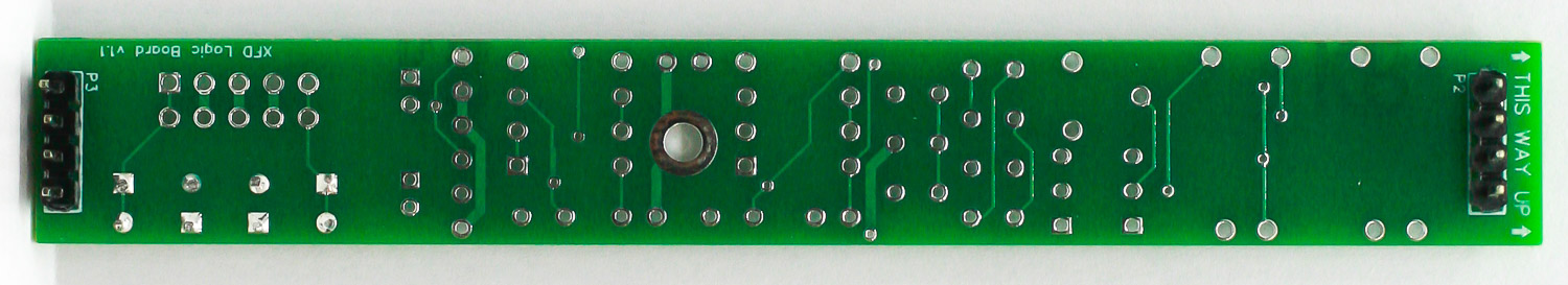
XFD – Main Board Header Pins
IC SOCKETS
IC Sockets are next up on the list. When populating them, make sure to align the semi-circular notch in the socket with the same looking notch in the silkscreen. Once you have them in there, an easy way to get them flat is to only solder one leg of each. Then you can go back and reheat the solder joint and gently apply pressure to sit them flat. Then go back and solder all the remaining legs on the IC sockets.
XFD – IC SOCKETS
ELECTROLYTIC CAPACITORS
Electrolytic capacitors are polarized, so make sure when you are placing them that you get the longer leg in the square hole, closer to the + symbol. Once in, flip your project over, solder and clip any excess leads.
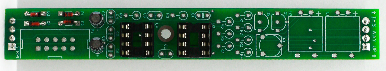
XFD – Electrolytic Capacitors
RESISTORS
Next put in the stand-up resistors as shown below. It can help to bend the resistors before placing them into the PCB. Carefully turn the PCB over and solder resistors in place.
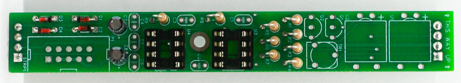
XFD – Resistors
TRANSISTORS
Place the transistors into the PCB as shown below by aligning the shape of the transistor with the silk screen. Carefully turn the PCB over and solder in place. Clip excess leads.
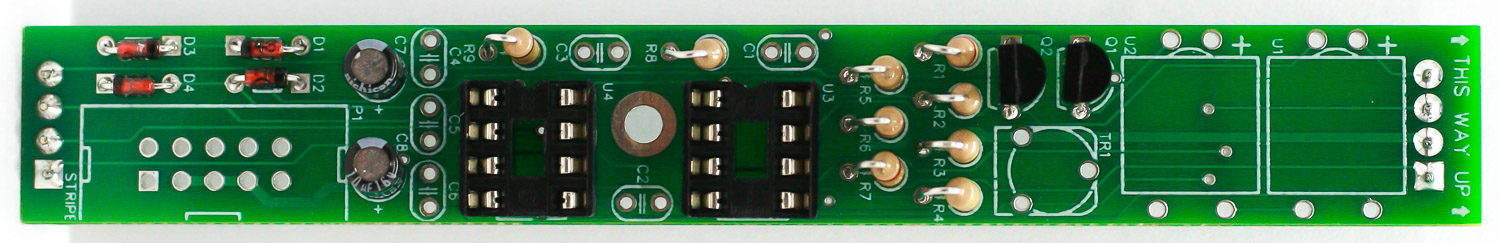
XFD – Transistors
CERAMIC CAPACITORS
ATTENTION! The XFD can be built with high-speed operational amplifiers if you care to use it with with video signals. If you bought the high-speed op-amp kit then you will need to populate all of the ceramic capacitors (comes with kit). If you purchased the normal audio version, just populate the two ceramic capacitors as shown below. Place, turn over to solder then clip excess leads.
XFD – Ceramic Capacitors
TRIM POT & VACTROLS
Place the trim pot into the PCB then carefully turn over to solder in place. Then place the two vactrols in place as shown below by aligning the small “+” mark on the Vactrol with the “+” on the PCB. These will only function if oriented properly!
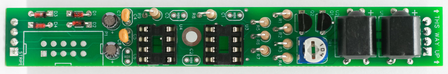
XFD – Trim Pot & Vactrols
10-PIN POWER HEADER
Place the 10-pin power header into the PCB by aligning the notch on the header with the notch on the silk screen. Turn over to solder in place.
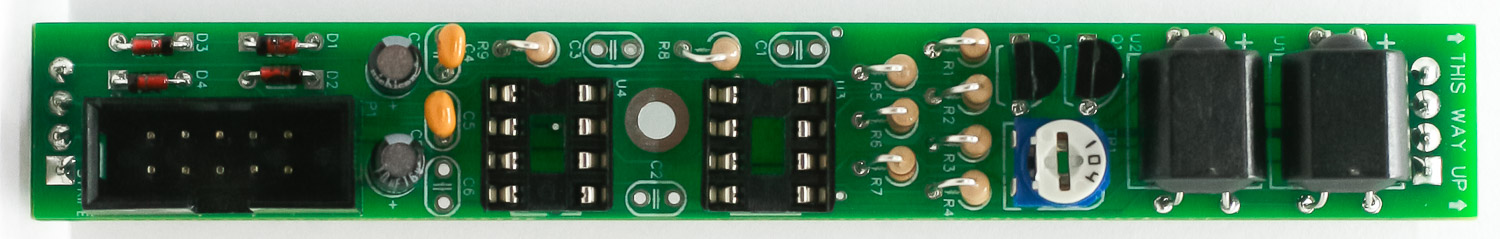
XFD – Power Header
ICs
next insert the ICs into their sockets. Following the BOM, insert each IC into its respective socket, making sure to align the notches in the ICs with the same notches in BOTH the sockets and the silkscreen.
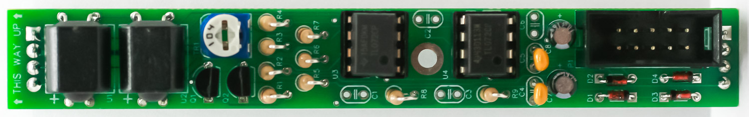
XFD – ICs
CONTROL BOARD SOCKETS
Take the two header pin sockets and place them into the control PCB. Make sure they are perfectly vertical, then carefully turn over and solder in place. One way to do this is to plug the the sockets directly into the logic board headers, then place the PCB on top and solder.
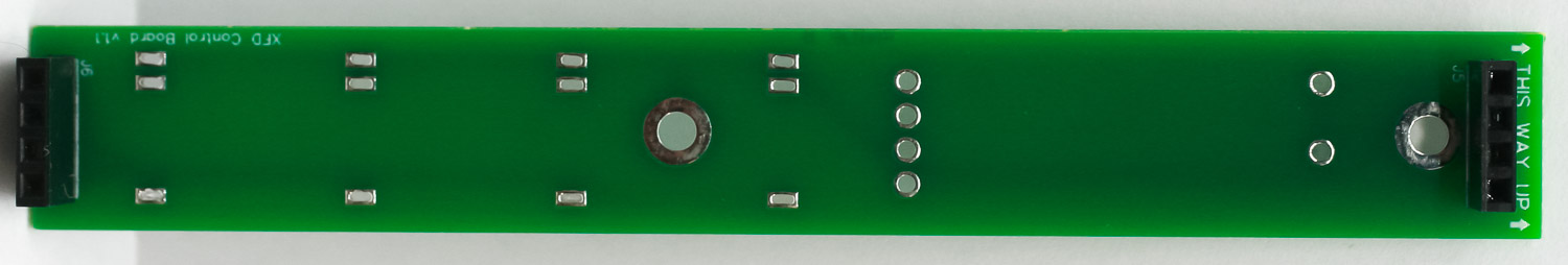
XFD – Control Board Sockets
SLIDE POT
Place the slide pot into the PCB, carefully turn over and solder in place.
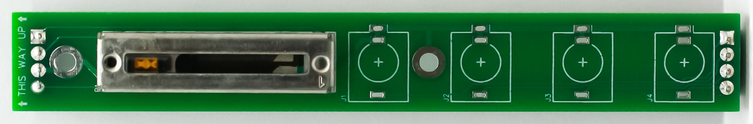
XFD – SLIDE POT
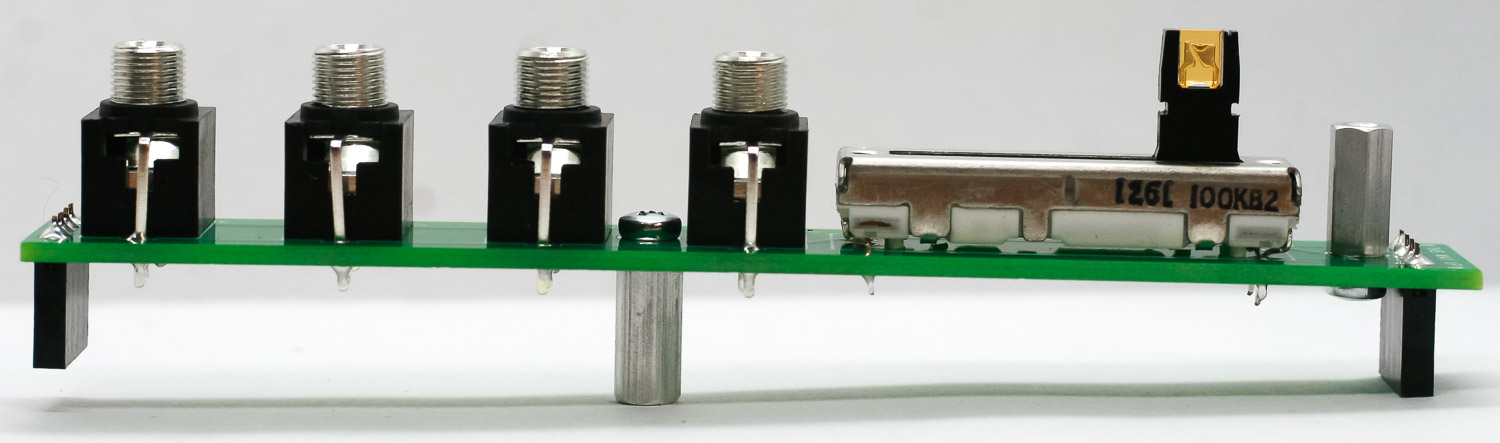
JACKS
Carefully place the jacks into the PCB as shown below. You can use the panel to help align them properly. Turn over and solder in place.
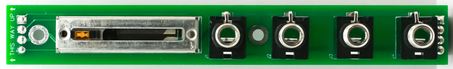
XFD – Jacks 1
STANDOFFS
Place and screw down the two metal standoffs as shown below. The 10mm standoff faces upward, connecting to the panel. The 11mm standoff faces downward, connecting the two PCBs.
XFD- Standoffs
PANEL PLACEMENT
Place the panel onto the control board and add the jack nuts and black screw onto the header.
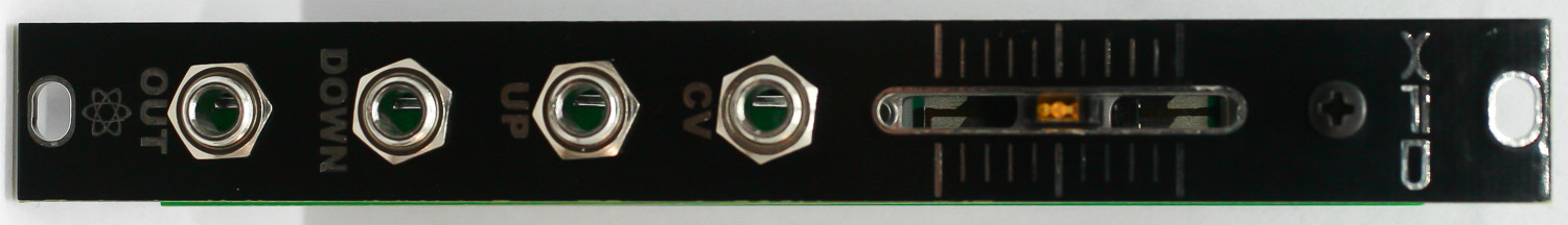
XFD – Panel Placement
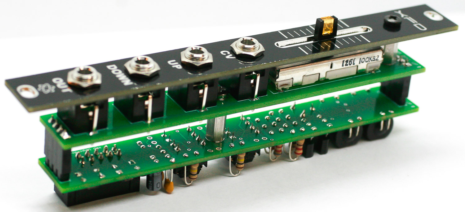
MAIN & CONTROL BOARD CONNECTION
Connect the main and control boards together by aligning the header pins and sockets and then screw in the screw into the standoff.
XFD – Control & Main Board Connection
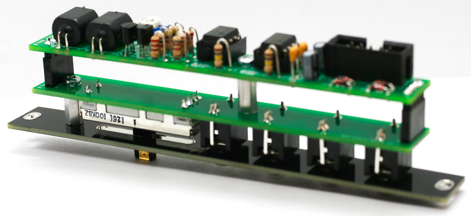
XFD – Board Connections
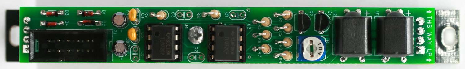
FINAL PROJECT
Congrats! Your XFD is complete. You can now test and calibrate you module.
XFD – Final Project
Calibration
Move the slide pot to the the center of the throw (at the detent). If you look at the sides of the vactrol, you can see how bright the internal LEDs are. Turn the trim pot on the back until both LEDs are approximately the same brightness.
Patch an audio signal into the UP jack, then slide the pot all the way down. The pot should go from completely cut out to full signal when you slide it upwards.
Now move the audio signal to the DOWN jack. The pot should go from completely cut out to full signal when you slide it downward.
If this isn’t the case, adjust the rear trimmer until both the UP and DOWN inputs completely cut out properly.