


Important Links
Eurorack Version:
Assembly Instructions
9V Version:
Assembly Instructions
Bill of Materials
Schematic
Capacitor and Resistor Lookup Guide
EURORACK DIRT Filter 2.0 Assembly Instructions
If your PCB says “2.0” in the corner, use these instructions.
If your PCB says “2.2” in the corner, CLICK HERE.
If you’re looking for the 9V version, CLICK HERE FOR VERSION 2.2
Thank you for purchasing your EURORACK DIRT filter Kit, please follow the instructions to ensure that you have a fully functioning unit. This kit has some ‘no pop’ parts (meaning the PCB calls out for a part, but you don’t populate it), so please follow the BOM and these instructions and don’t populate from the PCB alone. Let’s get started!
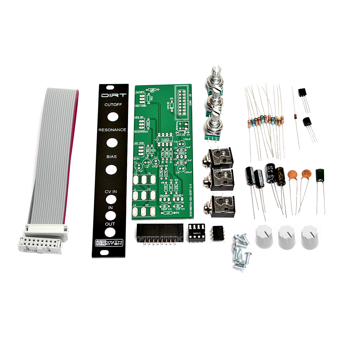
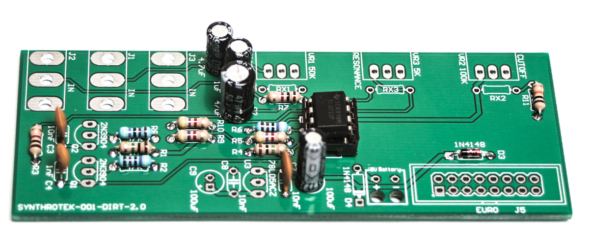
Eurorack DIRT filter visual BOM
RESISTORS & DIODES
First, start by populating the resistors and the diode, as shown below, then turn over on a firm surface to solder then clip your leads.
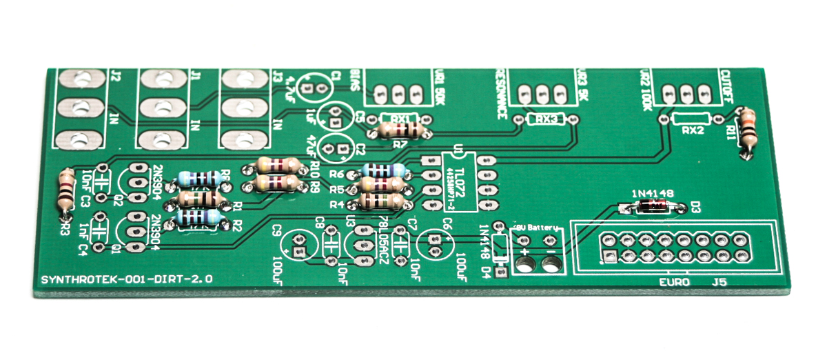
Eurorack DIRT Resistors & Diodes
SOCKET AND IC
Place the IC Socket in place by aligning the notch with the notch graphic on the PCB Silk Screen
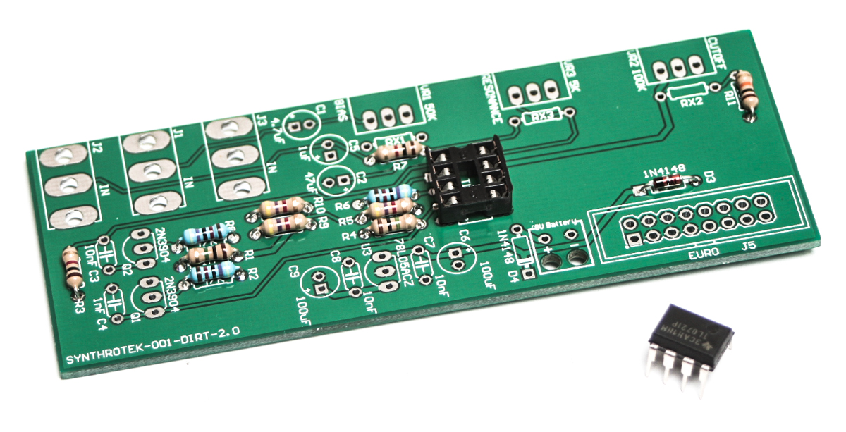
Dirt Filter IC Socket & IC
Now, place the IC in place, make sure you do not bend the pins when pressing down.
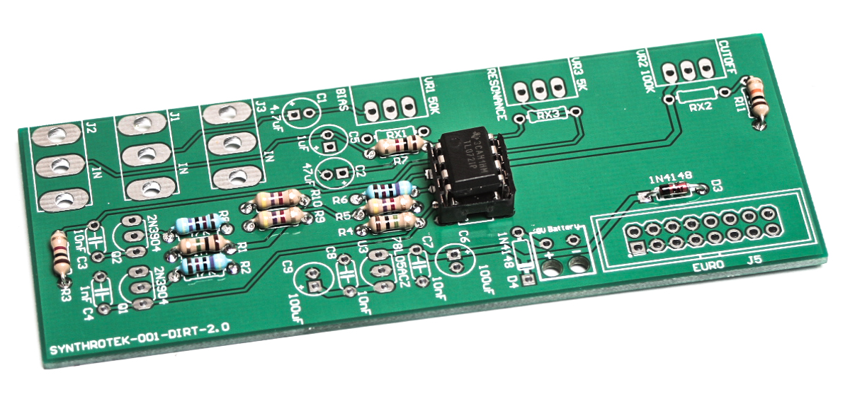
Dirt Filter IC
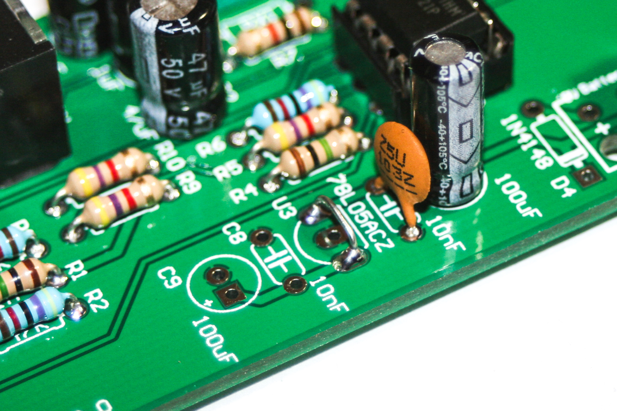
CAPACITORS
Place the capacitors in place and solder and clip leads. Make sure you orient the electrolytic capacitors in correctly. The longer lead needs to be inserted into the hole that has the “+” marking near it.
Dirt Filter Capacitors
TRANSISTORS
Add the two transistors as shown below by aligning the flat side of the transistor with the flat side of the graphic on the PCB silk screen. Turn over, solder and clip leads.
Dirt Filter Transistors
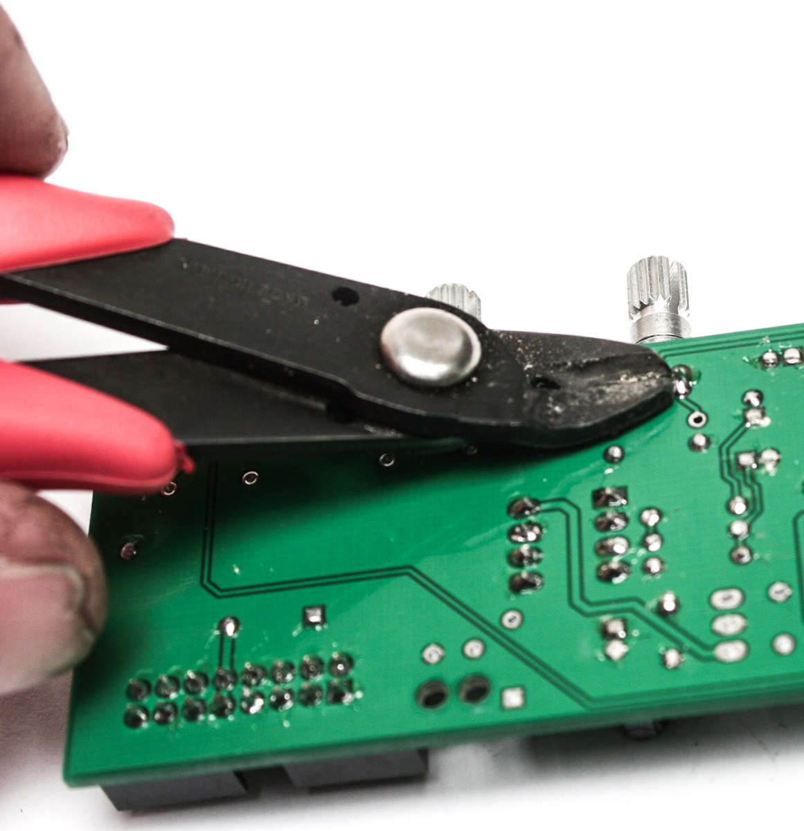
POTENTIOMETERS & JACKS & 16 PIN HEADER
First trim the alignment nub off the pots, as this will create a ‘wanky’ front panel.

Don’t forget to cut the nubs on the potentiometers as neccesary.
First place the 16-Pin shrouded header in place, turn over and solder. Next add the Pots and Jacks, solder then trim.
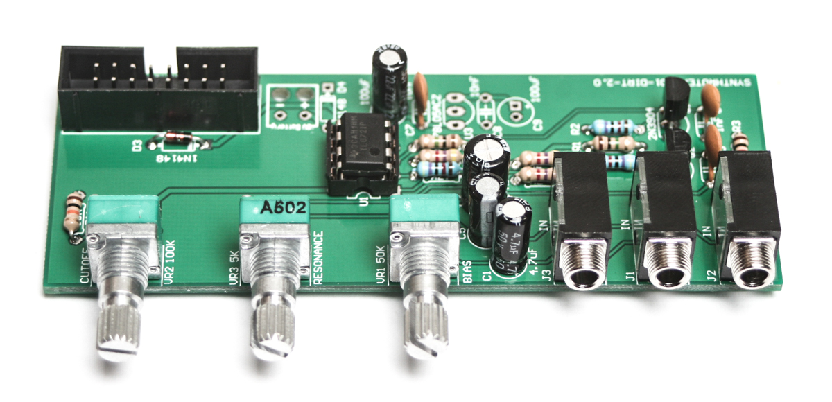
Dirt Filter Pots and jacks
Trim Pot leads
Trim Jack Leads
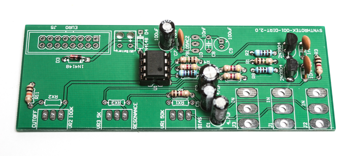
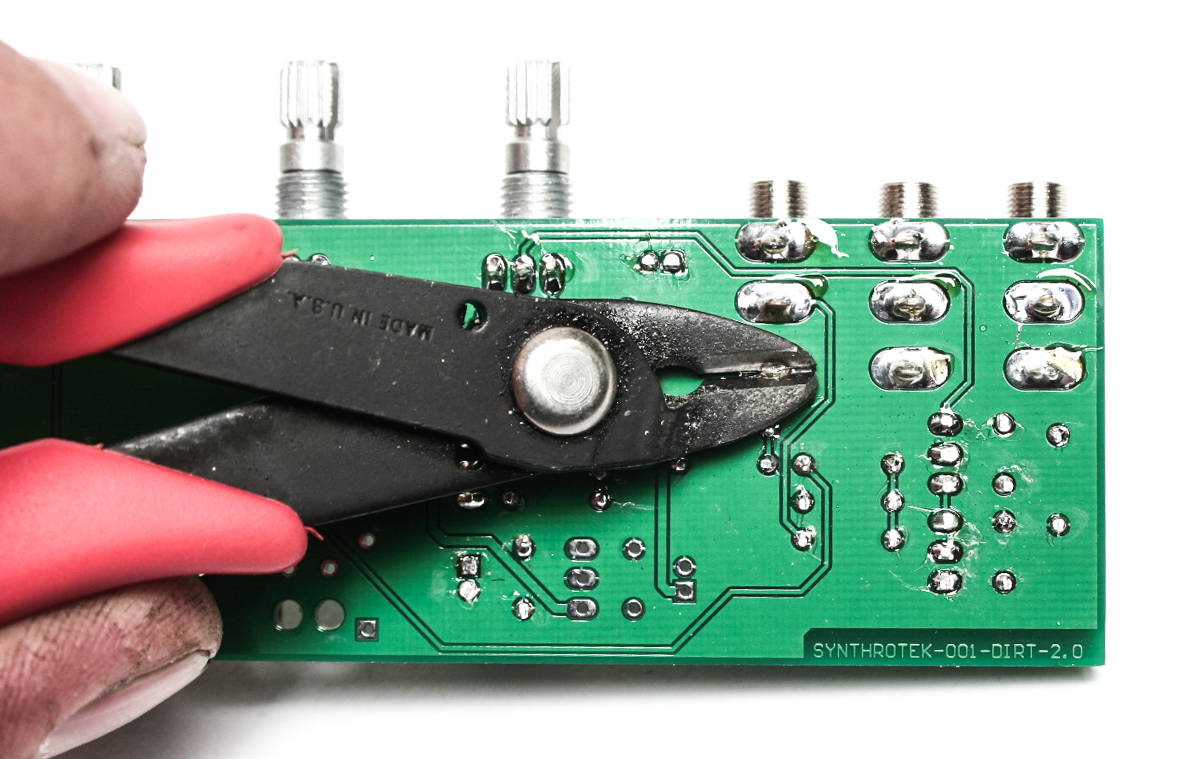
VOTAGE REGULATOR JUMPER
IMPORTANT!
For the eurorack version of the Dirt filter, you will not need the 5V voltage regulator, BUT we still need power to flow to the circuit. Take a spare resistor lead clipping and insert it into pins 1 and 3 of on the “78L05ACZ” silk screen area on the PCB. Pins 1 and 3 are the two outer-most holes. Ignore the center hole.
Voltage Regulator Jumper
FRONT PANEL & KNOBS
Add the front panel to your unit and tighten down the nuts carefully and do not over-tighten. The knobs can now be added and aligned as shown below.
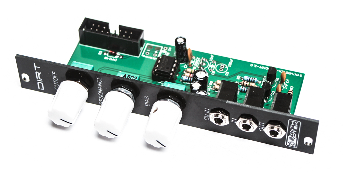
Front Panel and Knobs
CONGRATS! You are now done with your project and can test the unit in your eurorack system. If you have any questions or need help debugging, please first refer to our troubleshooting guide BY CLICKING HERE. If this gets you nowhere, please contact us by email for support. Thank you again for purchasing your kit from Synthrotek!