


Important Links
Quick Start Guide
Product Page
Store Page
Assembly Instructions
Bill of Materials
Capacitor and Resistor Lookup Guide
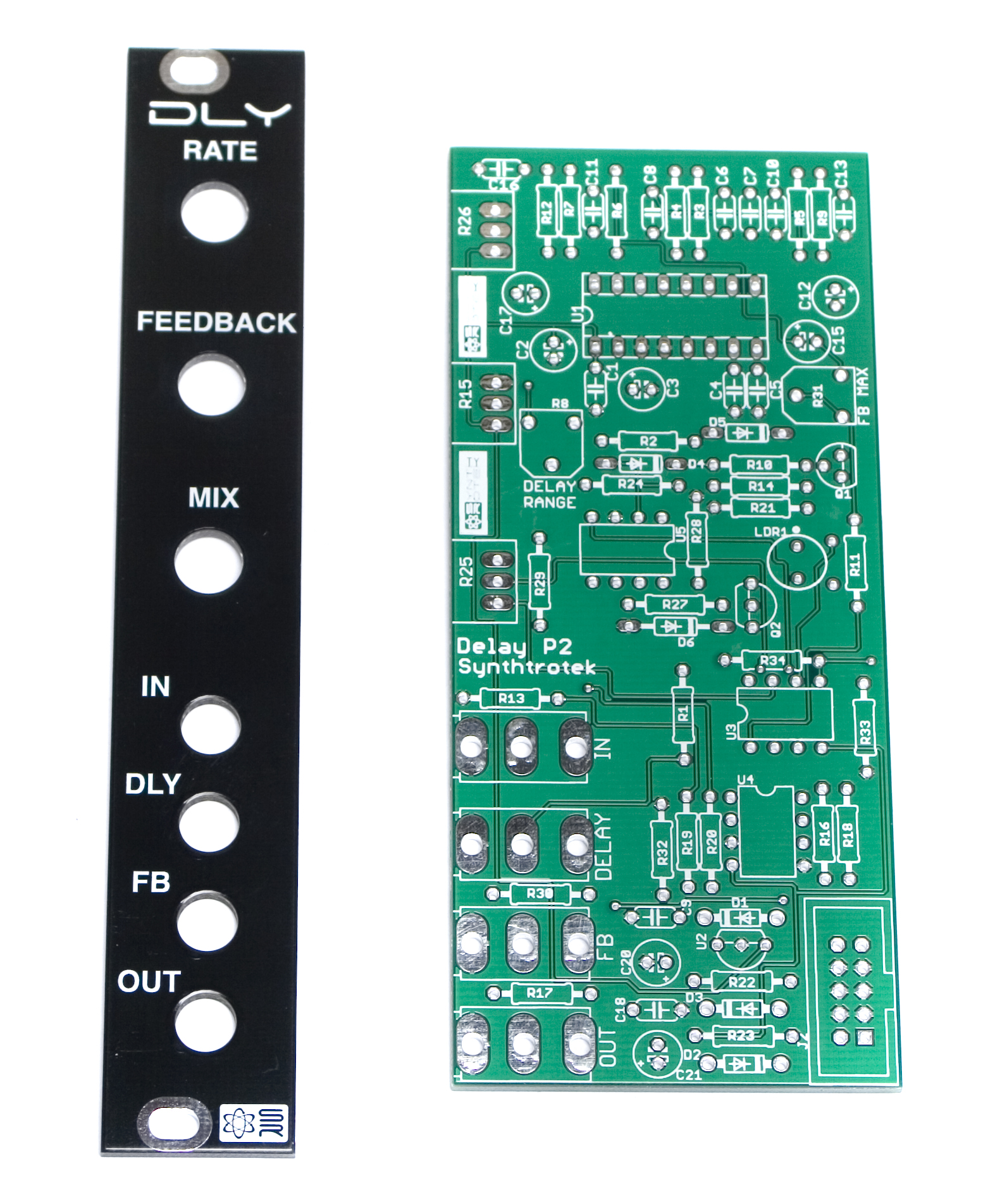
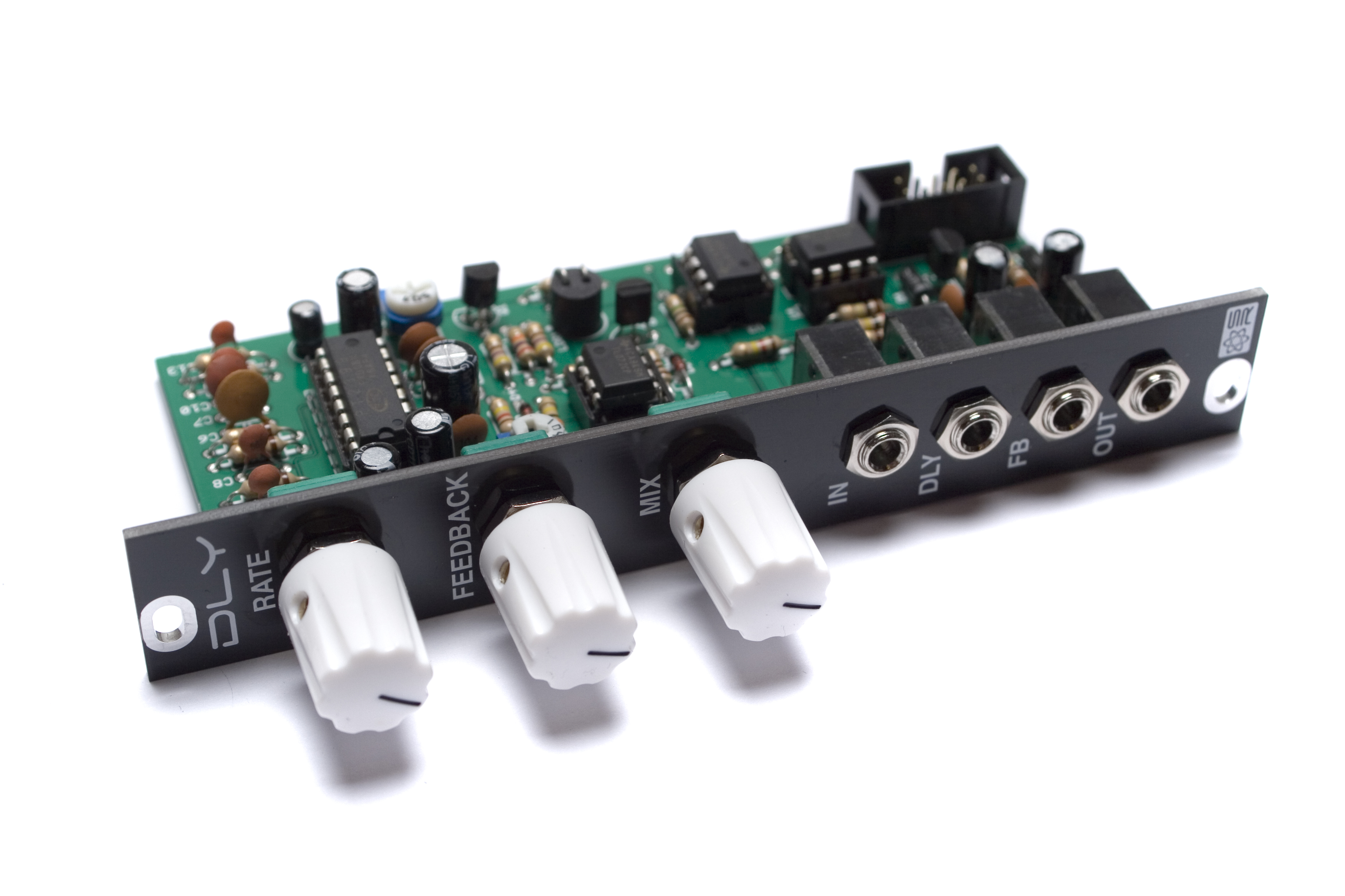
Synthrotek DLY PCB and Panel Set
Thank you for purchasing the Synthrotek DLY Eurorack module kit!
ATTN: Please follow the BOM and these instructions and don’t populate from the PCB alone. Also sometimes we cannot get the exact pictured components, so please look over your parts and check the codes first.
If you’ve received your parts and ready to build, the first thing you should do is to check to make sure you have all the parts. Check your kit against the DLY BOM. If you’re missing anything we’ll send it to you free of charge.
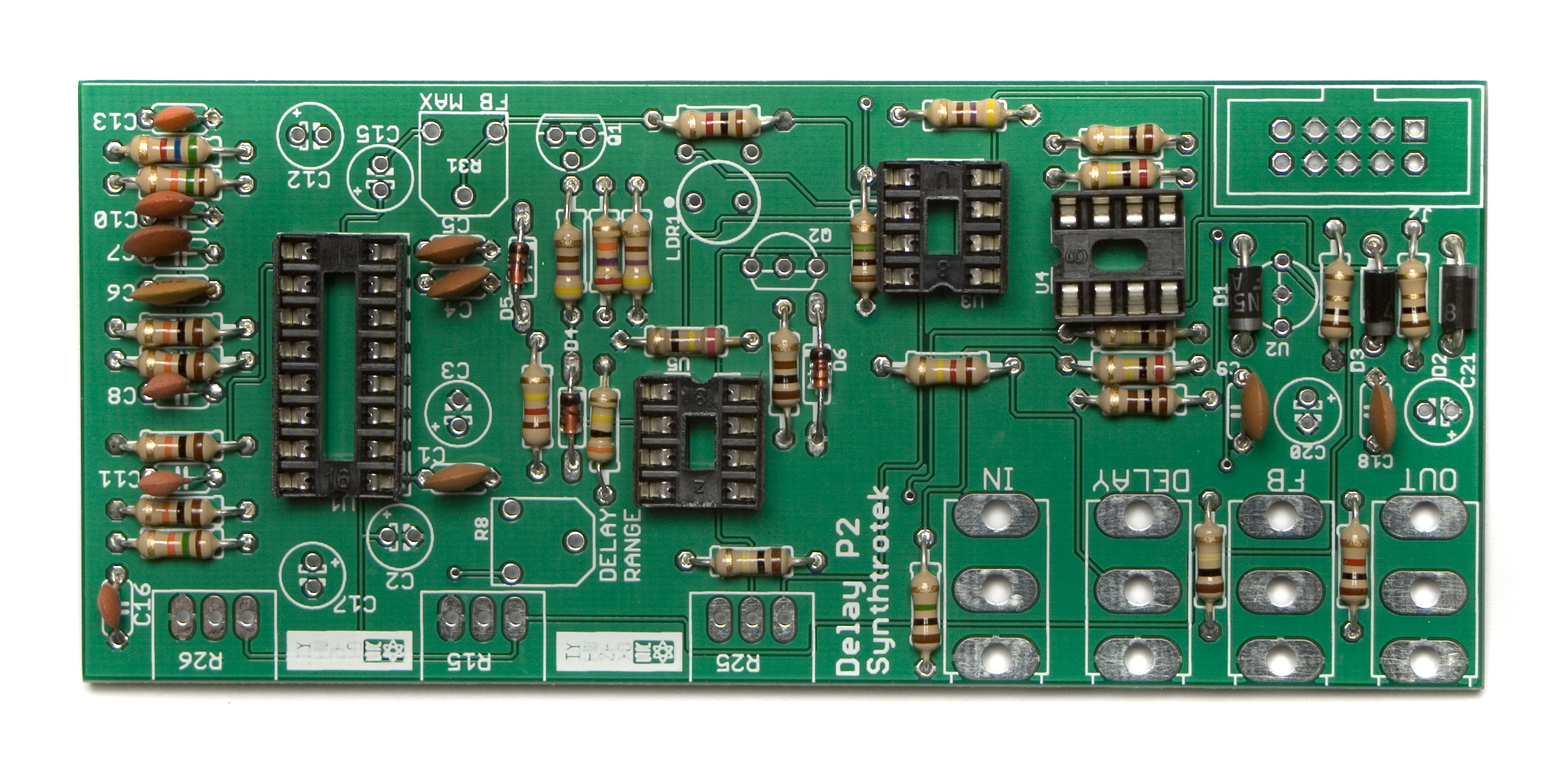
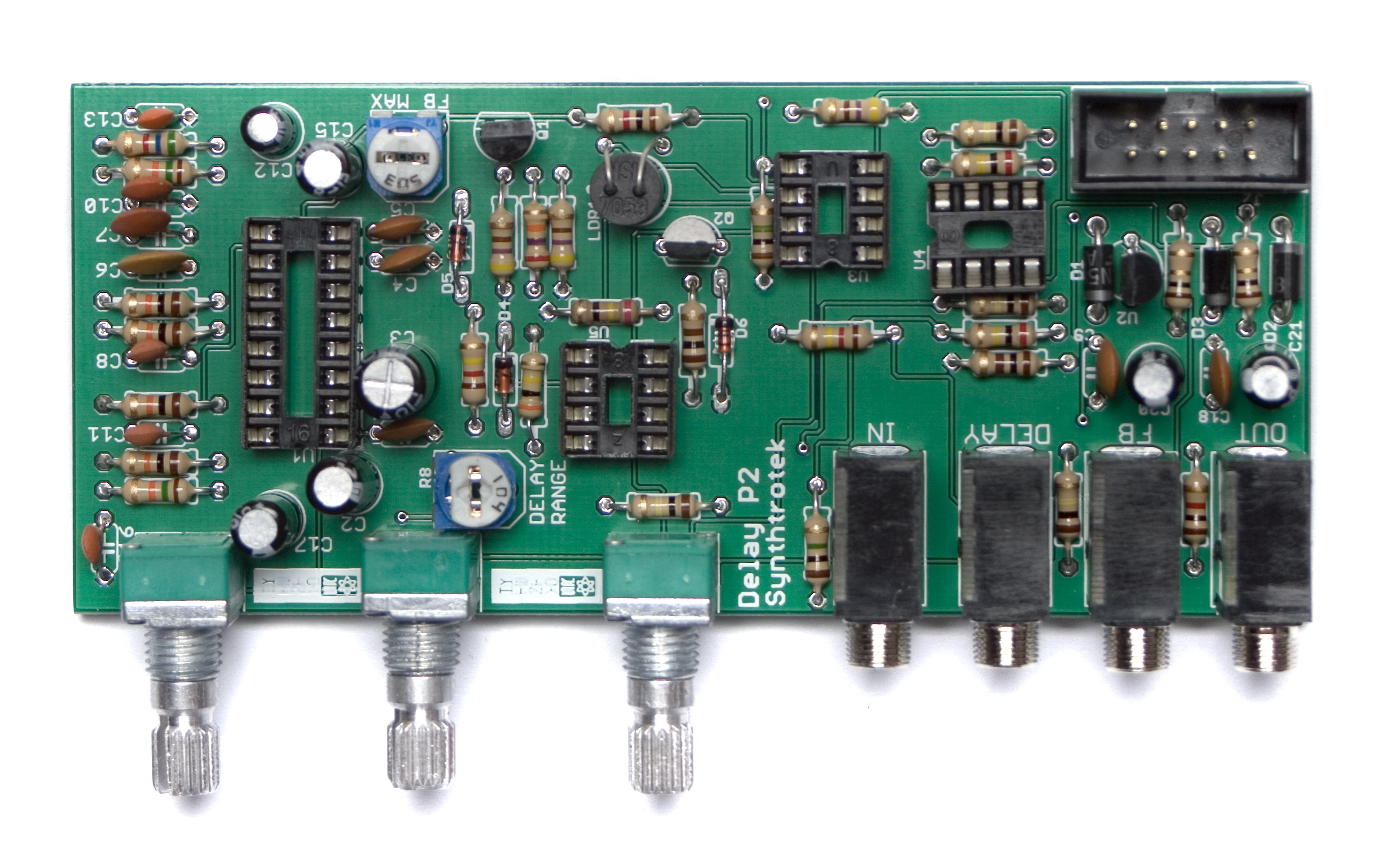
Resistors
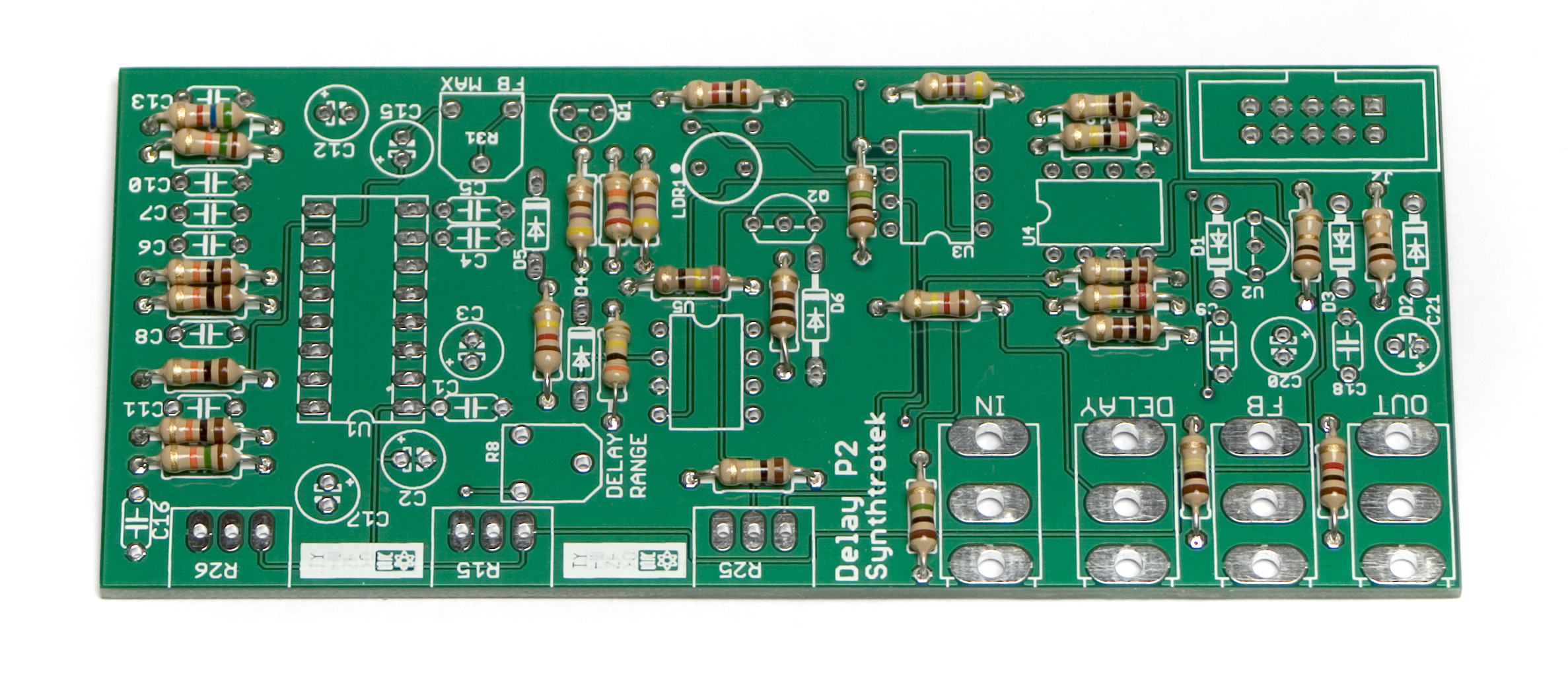
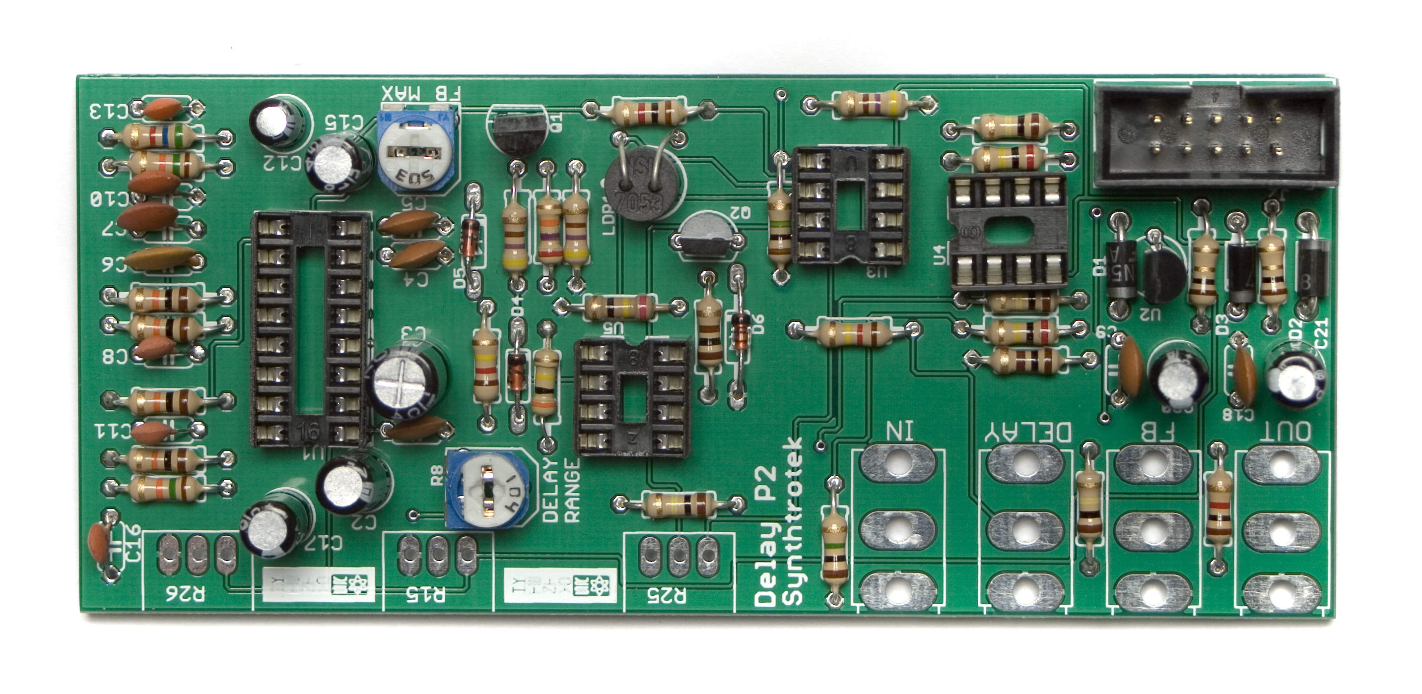
DLY Resistors
First up is the resistors. Populate them according to the BOM, and then flip the board over onto a flat surface, then solder and clip your leads. Using a flat rigid card or another PCB can help hold the resistors in place as you turn the board over.
ATTN: R13 is optional, the circuit will not be affected if that resistor is not soldered in.
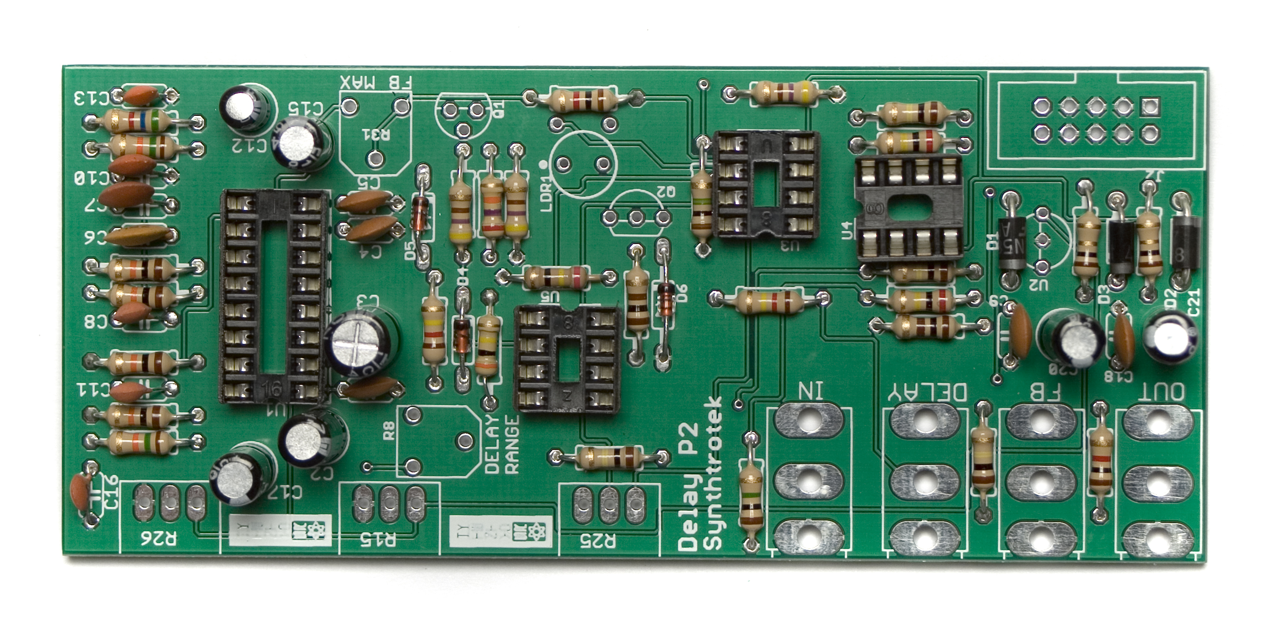
Diodes
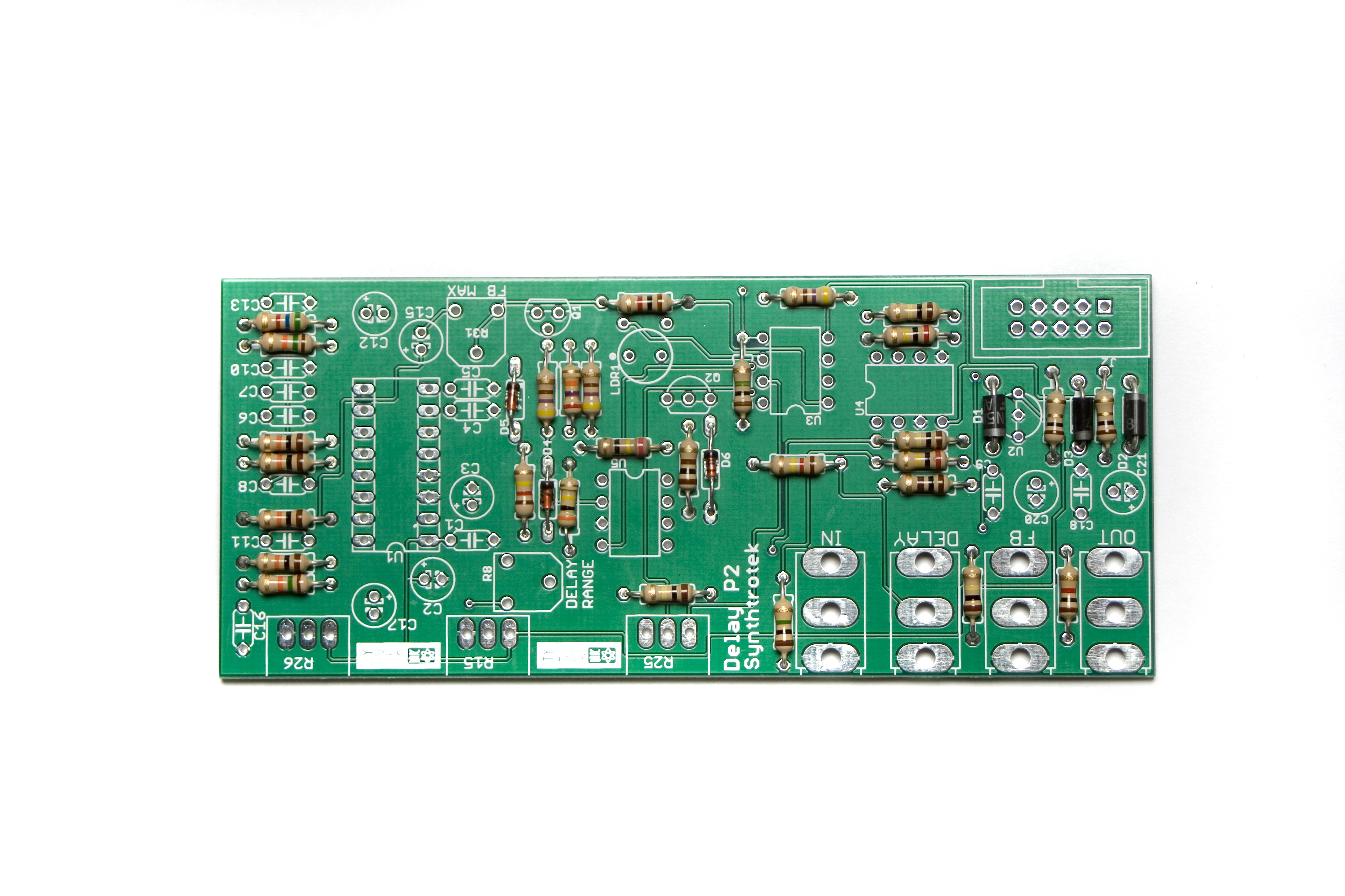
DLY Diodes
Next up are the Diodes. Insert them into their proper places according to the BOM, with the stripe (cathode) of the diode matching the direction of the stripe on the silkscreen. Diodes are polarized components and can cause big issues if not soldered in properly.
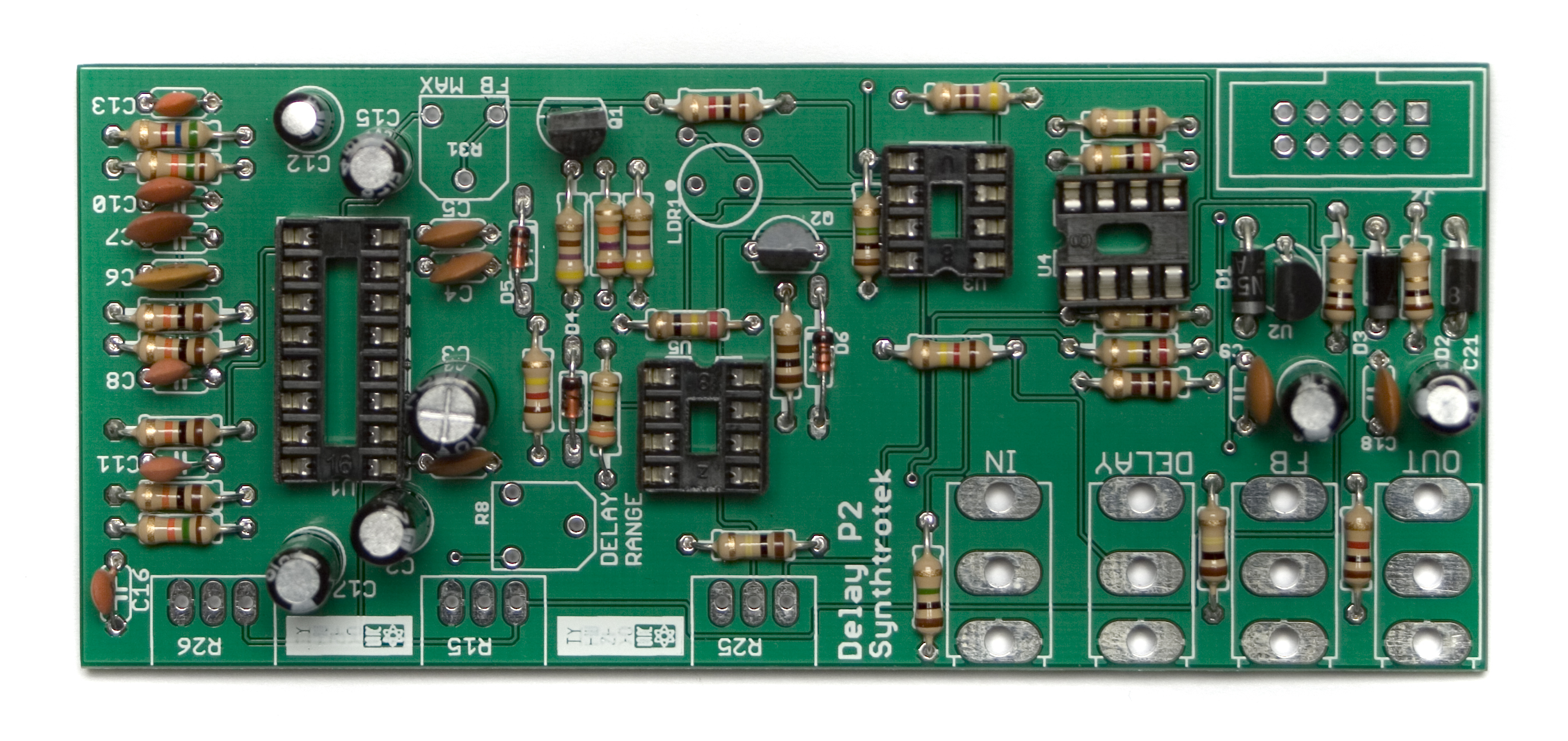
IC Sockets
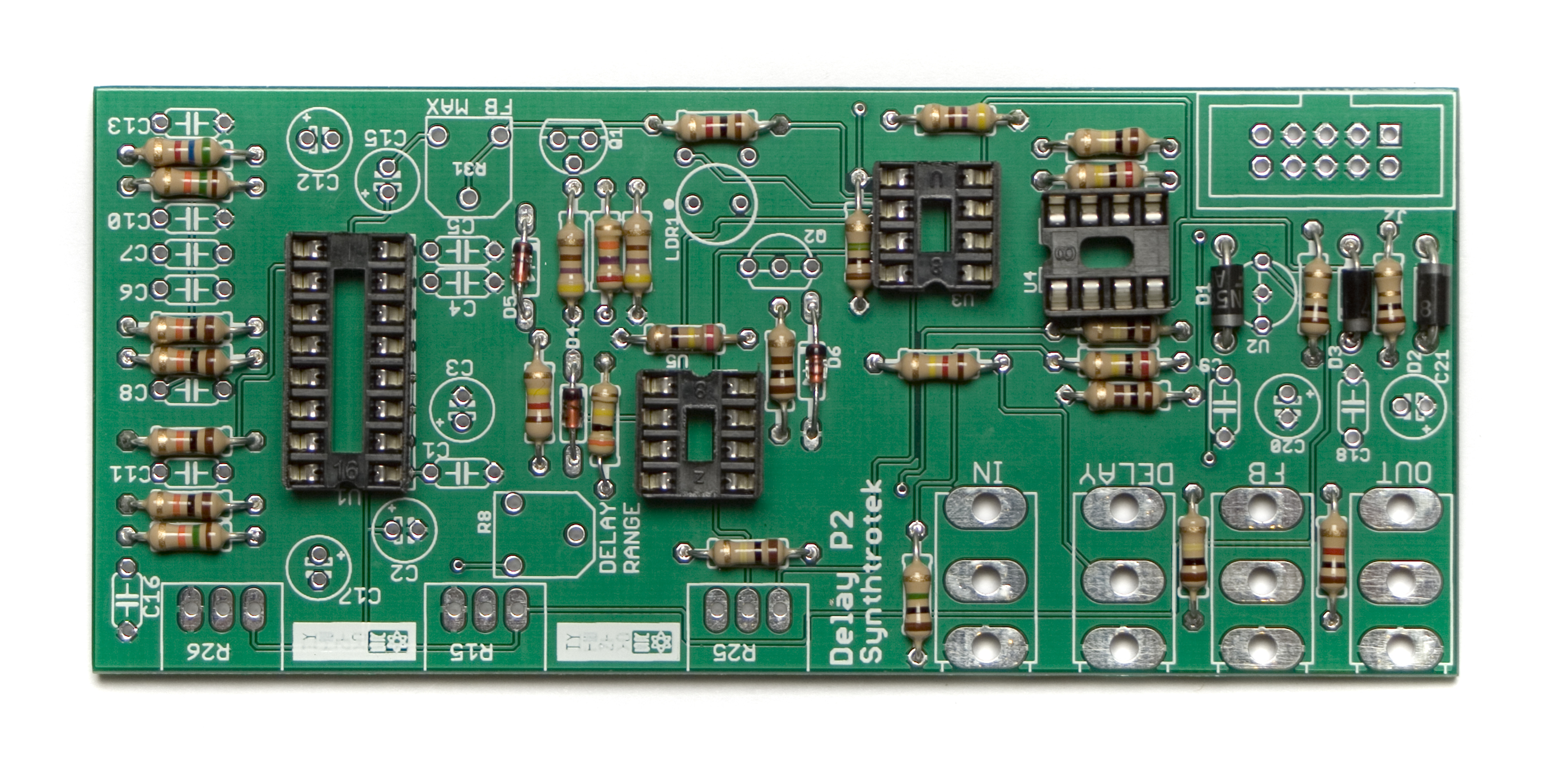
DLY IC Sockets
Now the IC sockets can be populated. Insert them into the board, making sure to align the notch, or the side with the ‘U’ shape in it, with the side of the silkscreen that has that same marking. Then flip over onto a flat surface and solder. One way to keep the IC sockets from falling out is to slightly bend one leg, or two legs on opposing corners.
Ceramic Capacitors
DLY Ceramic Capacitors
Ceramic capacitors are non-polarized, so it doesn’t matter which direction they go in their spots, just that they make it into their proper spots. The PT2399 chip is very particular about which value caps it has in which spots. Once they are all populated, flip over onto a hard surface and solder. One tip for getting these guys a little flatter is to only solder one leg first, then you can move them a little, and solder the other leg in place. Clip all your leads afterwards.
Electrolytic Capacitors
DLY Electrolytic Capacitors
Next up are the Electrolytic capacitors. Unlike the Ceramic versions, these are polarized and can do some damage to themselves or the circuit if installed improperly. On the PCB’s silkscreen, there is a little ‘+’ symbol next to one of the solder pads. When placing the Capacitors, make sure that the longer lead goes through the solder pad with the ‘+’ next to it, and that the stripe is pointing away from that side. Once you have all the Capacitors in place, flip over and solder your leads.
Transistors and Voltage Regulator
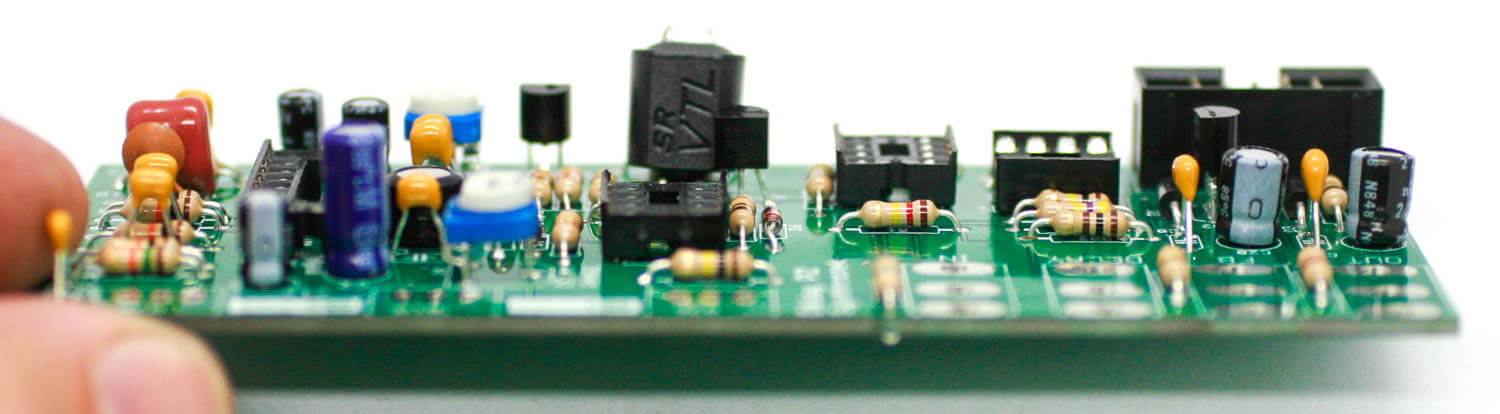
DLY Transistors and Voltage Regulator
When inserting the transistors into the board, align the flat side of the transistor with the flat side on the matching silkscreen, like in the picture above. The voltage regulator is going to be populated in the same way. Then flip over and solder your components.
Trimmer Potentiometers
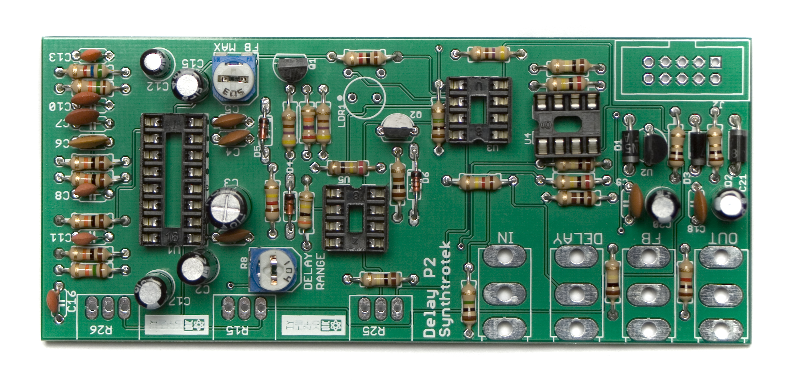
DLY Trim Pots
Next up are the two trim pots. Align them so that the flat sides match the flat part of the silkscreen, then flip over and solder them in place.
Eurorack Power and Vactrol
We are now ready to insert the Vactrol. Two important things to note:
1. You MUST use the vactrol provided with your DLY kit or PCB/Panel set. If you use any other vactrol or optocoupler, your circuit may not work.
2. Vactrols are very sensitive to overheating. Be careful not to heat them more than a second on each leg. If you need to reflow a solder joint, wait a few minutes for the vactrol to cool.
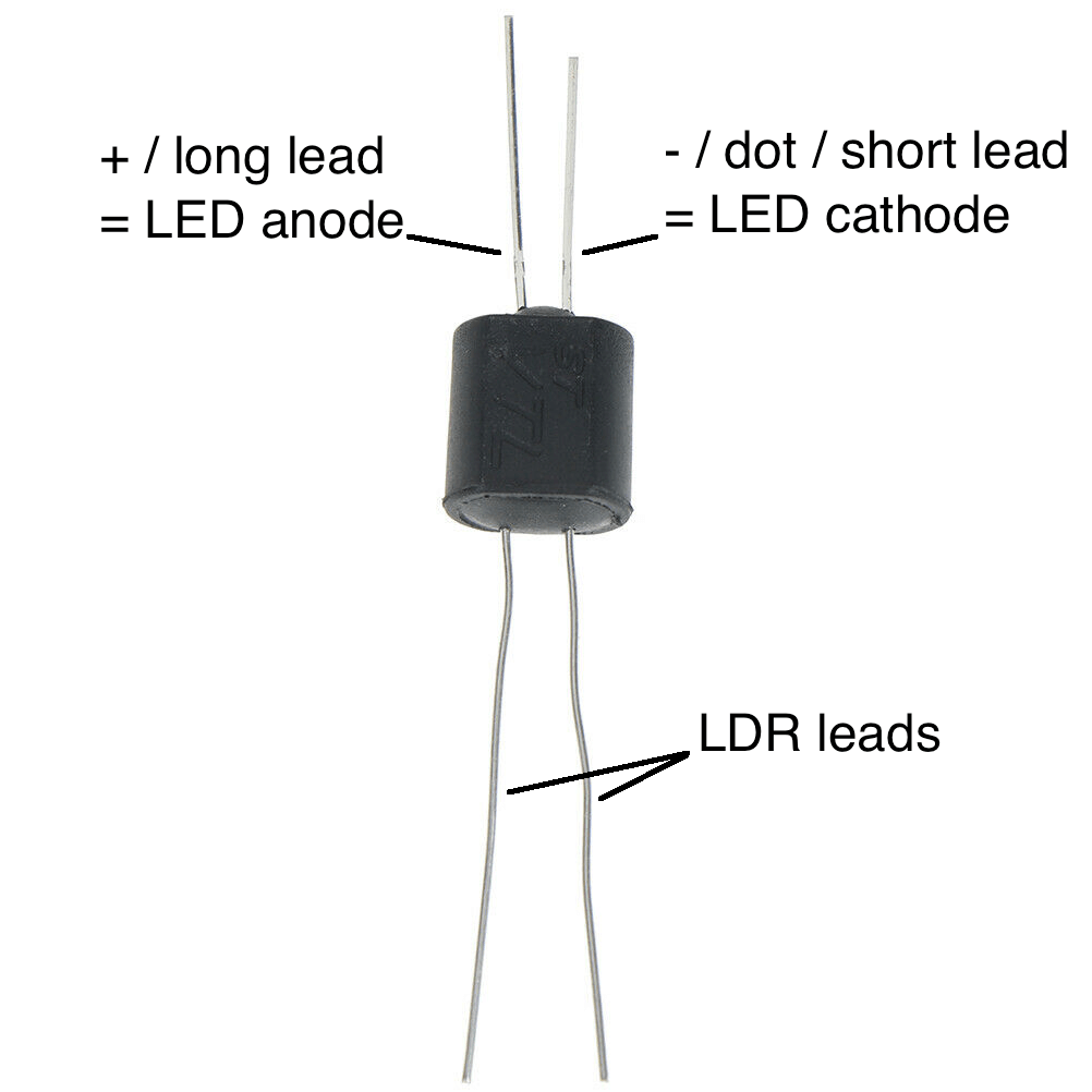
NSL-7053 Vactrol
When inserting the NSL-7053 vactrol into the board, align the dot on the side of it with the dot on the silkscreen. Put the shorter set of legs through the solder pads inside of the circle, so that the body of the vactrol sits in the circle, and the longer legs stretch out to the other two holes.
DLY Power Connector and NSL-7053 Vactrol
VTL5C3 Vactrol
There is a small “+” sign on the side of the vactrol that needs to be oriented on the OPPOSITE side of the dot on the PCB. Look for the red + in the picture below for the proper alignment.
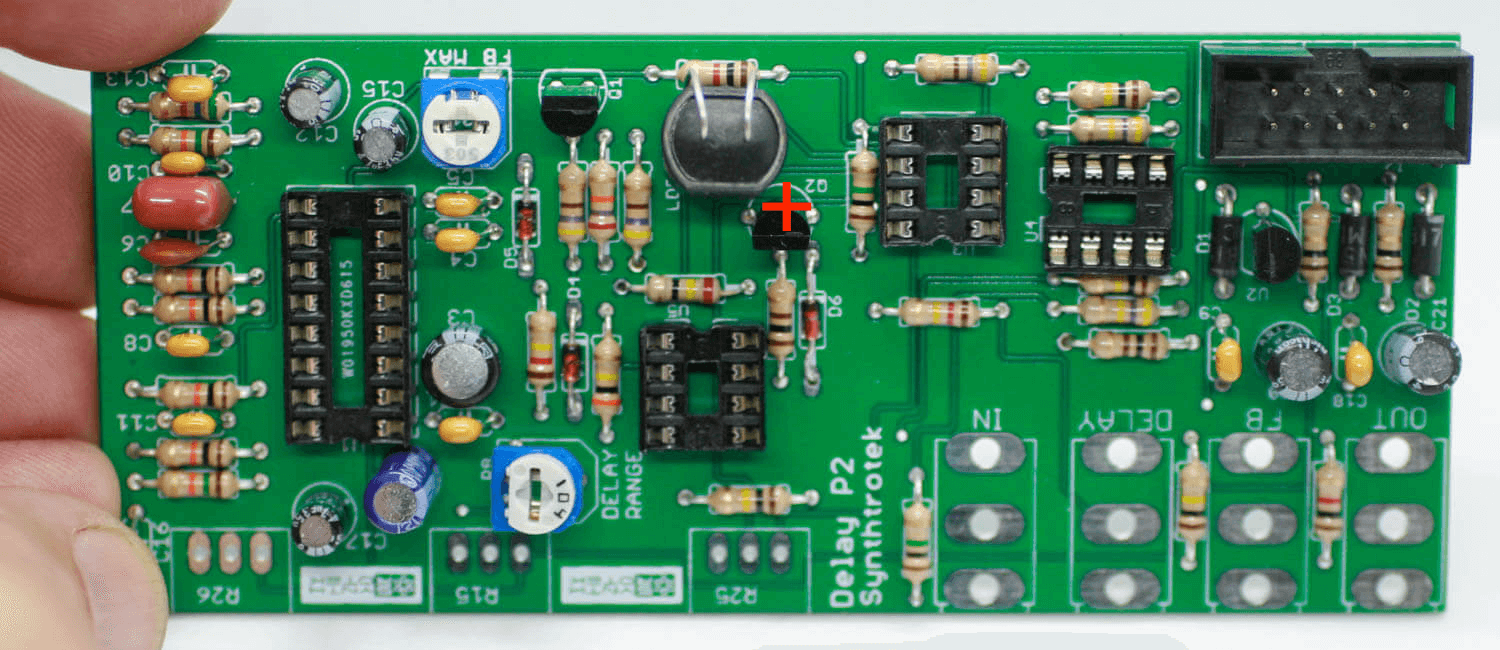
Align the + on the VTL5C3 with the red plus in the picture
DLY Power Connector and VTL5C3 Vactrol 2
Next, align the notch on the 10 pin Eurorack power connector with the notch in the silkscreen, as shown above. Flip the board over and solder everything in place.
Jacks and Potentiometers
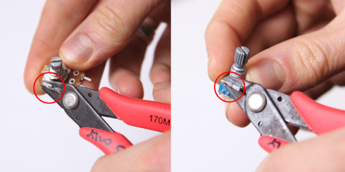
Don’t forget to cut the nubs on the potentiometers as necessary.
After trimming the nubs on your pots (if they are present), place the pots in the board first, turn the board over with the pots in place, and then solder ONLY THE CENTER PIN to the PCB. Do likewise for the jacks now. Place the the jacks in and on a flat surface ONLY THE CENTER PIN to the PCB.
DLY Jacks and Potentiometers
Once you have all the jacks and potentiometers attached, you can test fit the front panel to make sure that all of your components fit into the front panel, and that everything is straight. If it is, go ahead and solder the rest of the legs on the jacks and potentiometers.
ICs
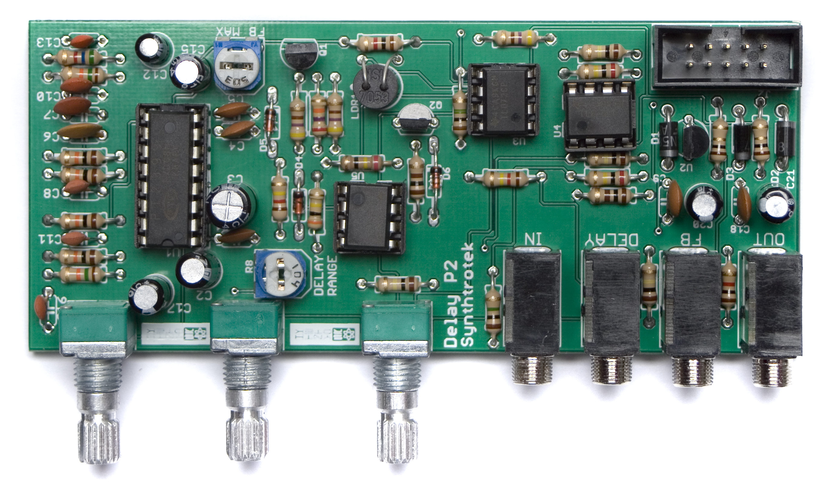
DLY ICs
Next, insert the ICs into their proper sockets, making sure that the notches on the ICs match the notch on both the socket and the PCB silkscreen.
Front Panel
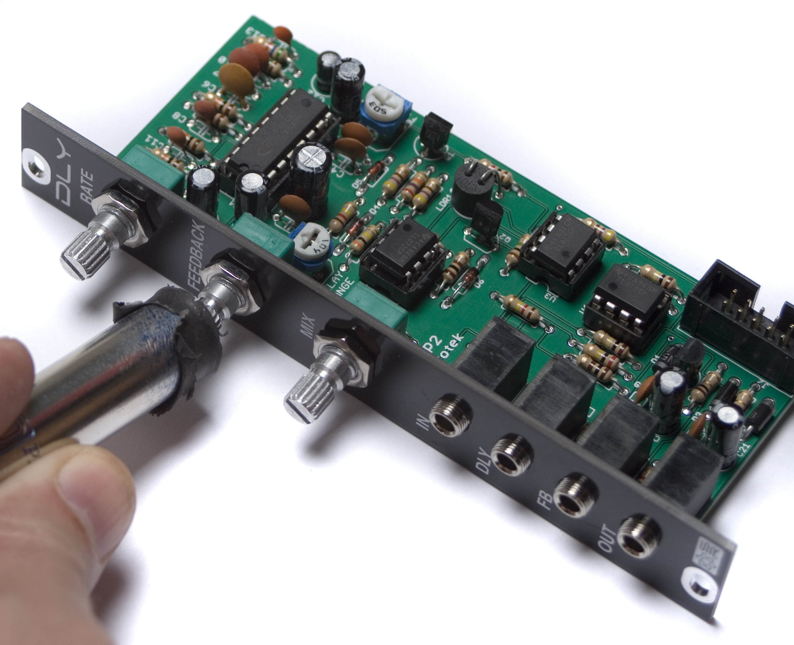
DLY Front Panel
Place all the nuts onto the potentiometers and the threaded parts of the jacks, and hand tighten first. Then go back with a 10mm and 8mm socket, respectively, and tighten the nuts so the front panel is snug.
DO NOT OVERTIGHTEN, it may damage some of the components and put undue stress on the PCB.
Finished Module
Finished DLY
Calibrating and Testing Procedures
—-CALIBRATING FEEDBACK—-
First thing to check is if the DLY will self-oscillate. Set the RATE knob fully counter clockwise, set the FEEDBACK knob fully clockwise, and set the MIX knob fully clockwise.
Slowly turn the FB MAX trimpot clockwise until you start to hear the DLY self-oscillate. Rotate the FEEDBACK knob to 3 o’clock and see if the oscillation will stop. From here you will want to dial the FB MAX trimpot to taste. We typically aim for the DLY to self-oscillate around 3 o’clock on the FEEDBACK knob (when the RATE knob is fully counter clockwise and the MIX knob is fully clockwise).
—-CALIBRATING DELAY RANGE—-
Just like you did above, set the DLY up to self-oscillate. This time, turn the RATE knob fully clockwise and slowly turn the DELAY RANGE trimpot clockwise until the delay goes as slow as possible before “getting weird.” That’s usually about 1.13 seconds. You may want to dial the DELAY RANGE trimpot to taste. We set the DLY up to go as slow as possible before the delay starts to break up and freak out.
—-TESTING INPUTS—-
Set all knobs to noon and take an audio source (preferably non drone based) and plug it into IN. Make sure that the audio is passing through and is being delayed.
Take a Bipolar (-5/+5V) Envelope, LFO, Offset, or Sample & Hold and plug it into the DLY input. You should be able to hear the speed of the delays change from fast to slow and vice versa. Unplug the DLY CV source.
Take a Unipolar (0-10V+) Envelope, Gate or an Offset and plug it into the FB input. This input is vactrol based and will only respond to Unipolar voltages. At 10V+ you should be able to hear the module self-oscillate. Take note that the FEEDBACK knob sets the starting point for CV over feedback!
By now you should be able to confirm that the DLY is working correctly.
Congratulations! You just successfully just built a DLY module from Synthrotek! You can check out all the info on the module, watch a demo video, or read the quick start guide over on the product page.
Thanks for choosing Synthrotek!
So what does R13 do? And why is it optional?
exactly, what difference does R13 make? how can we choose either option without knowing what they are..?
Hello,
R13 is the imput impedance resistor. There is no sound difference with or without this resistor.
Thanks,
-Patrick
Hi,
Is it possilbe to mod this to run at 15V
Daniel
Hey Daniel,
While it may be possible, we haven’t tried to do that, so you may need to build a little conversion board that turns the voltage down from 15 to 12.
Best,
-Patrick at Synthrotek
Thanks Patrick.
Thanks for the awesome kit and clear instructions. I’ve got a working delay on my hands but can’t get the time longer than say a long slapback. I’ve gone over my board but am missing something still. Can you point me to which components to focus on to control time?
Thanks,
Roy
Hey Roy,
Happy to hear your build went well!
Here is a link to our DLY quick start guide:
http://synthrotek.com/Manuals/DLY-QUICK-START-GUIDE.pdf
You’ll notice, by adjusting the trim pot closest to the panel, you can change the range of delay time.
If you’re planning to mod the DLY time, I would recomonend starting there.
-Zach
Built this and it was just about perfect – except when setting it up I noticed I have the trim pot installed the wrong way round, which made it a bit more difficult to set up. So I then spent a couple of hours trying to remove and swap them over. Oh dear now nothing works at all – except the Mix knob. The Delay was working for a while but the Feedback just did a couple then stopped. Do you have any suggestions what to look for? May the Vactrol has gone or something else? Any suggestions please! Ewan
Hey Ewan,
It could be that the vactrol has blown from having the trim pot mounted the wrong way.
But Definitely check that all traces around the trim pot are still connected. Desoldering components can lead to ripped vias or broken traces!
Once you check that, I would take a multi-meter to the vactrol. Check the voltage going into the dotted side of the vactrol and then check the resistance on the other two legs coming out the other side.
As you adjust the trim pot and feedback pot, you should see values changing respectively on both sides of the vactrol.
You can order DLY vactrols directly from us:
http://store.synthrotek.com/Vactrol
Just be sure to select the DLY option in the pull down menu!
Best,
-Zach
@Ewan Mathers
This happened to me also. Well the feedback just stopped on me, Im not sure why, but measure the vactrol diode with a meter on diode check, I bet its open circuit. They should measure around 1.5 one way and open the other. I have no idea why mine went, it “could” have shorted on something when I was pulling a module, but it was working in circuit one minute then dead the next. This leads to my Question : Zach whats the main difference between the Vactrols youre selecting? Do they have different LDR resistances or is it a diode characteristic? I shoved a standard NSL32 in its place and it seems to work fine. Ill get a DLY version next order but Im just curious as it still sounds great.
Cheers
@Steve Harmon
I was careless and tossed the included vactrol into a bin with others when I received the PCB/Panel. I have two questions:
1. Is there a way for me to test the vactrols to know which one is the DLY version?
2. Will the DLY vactrol in another build cause any problems – lets say the MST VCF?
thanks!
Hi, is there a schematic to download?
Hi Arnold, at this time, we don’t based upon our licensing agreements.
Hello! I am also having an issue with the delay time being awfully short — like a slapback — even after attempting to calibrate the delay range trim pot as is described on the assembly instructions page. When adjusting that pot, the delay goes from short slapback immediately into insane bursts of noise. Any thoughts? I really appreciate any guidance you can provide!
Hi Nick, I recommend going through and reflowing your solder joints, and if that doesn’t work, check your component values (resistors especially). When something is slightly off, one of these two fixes usually does the trick.