


Thank you for purchasing the Synthrotek BM 2HP Buff mult kit! This is an advanced build and only proceed If you feel like you can handle it. If not, get some help from a friend with experience or purchase a fully completed unit. This is partially a surface mount kit so that means that the parts are very small and it will take a fine tipped soldering iron tip and some tweezers in order be assembled appropriately.
Please build according to the BOM, and not these instructions or the pictures alone. Some components may have changed since these were written, or we may not be able to get the exact looking components in the pictures.
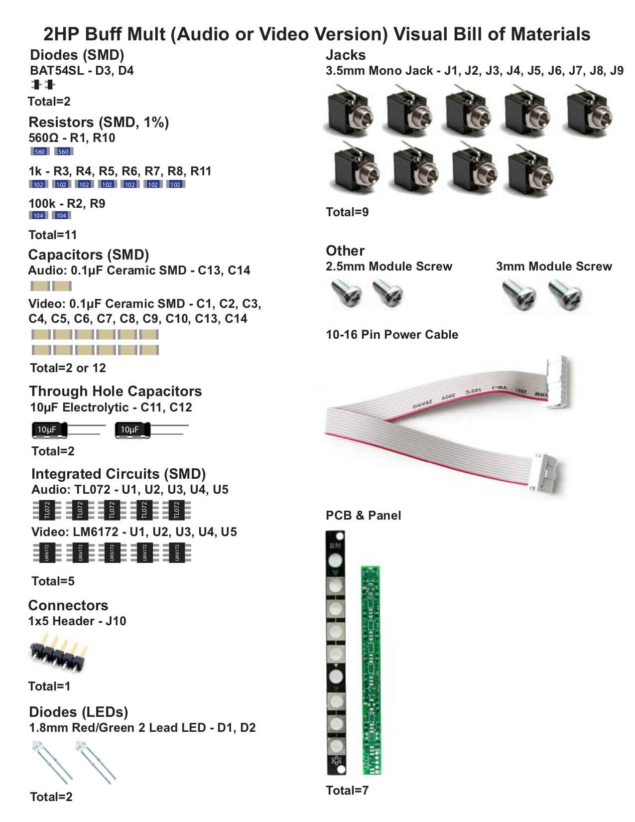 For a BOM with Mouser part numbers, click here.
DIODES
Place the diodes on the PCB as shown below and tack in place with your fine tipped soldering iron.
BM – Diodes
OP AMPS
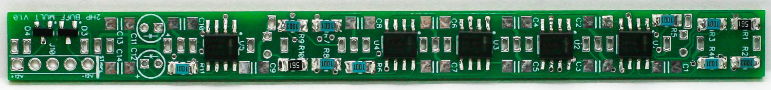
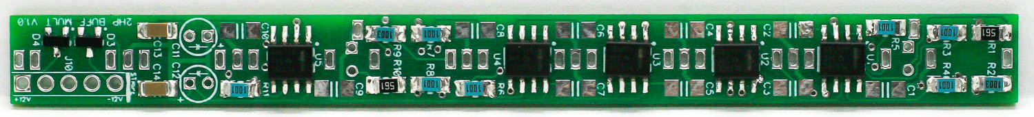
Place op-amps on the PCB as shown below. The dot on the PCB indicates pin “1” of the IC and needs to be placed toward the notch on the silkscreen. Solder in place carefully.
BM – Operational Amplifiers
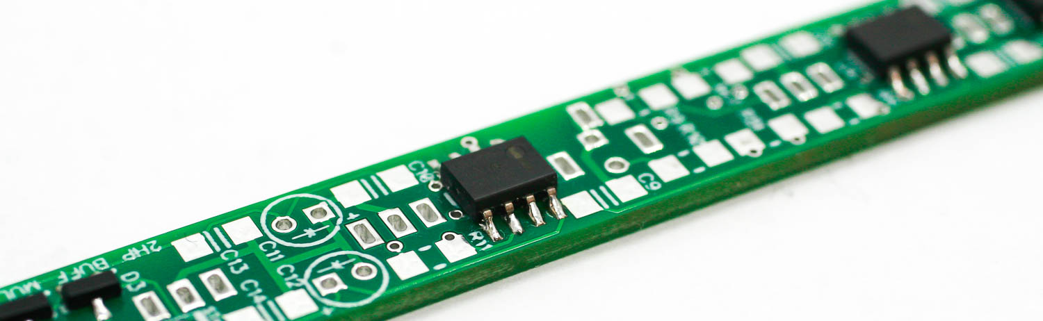
BM- Op Amp 2
RESISTORS
Place the resistors onto the PCB as shown below. Resistors are not polarized so they can be placed either direction. The blue resistors are 1% tolerance. Make sure you put the correct ones in the correct places. Carefully soldering in place.
BM – Resistors
CERAMIC CAPACITORS
Please note: the standard 2HP Buff Mult kit only requires two ceramic caps. There are callouts for more ceramic caps, but they are not necessary unless the circuit is being used for video.
Place the ceramic capacitors into the project as shown below. These ceramic capacitors are not polarized so they can be placed either direction. Carefully solder in place. You will notice that there are other places on the the PCB for more caps. When the BM is used for control voltage and audio you will not need to populate these caps. If you are using high speed op amps for modular video, you will need to populate these. The kit you purchase will include the parts you need.
BM- Ceramic Capacitors
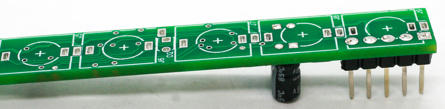
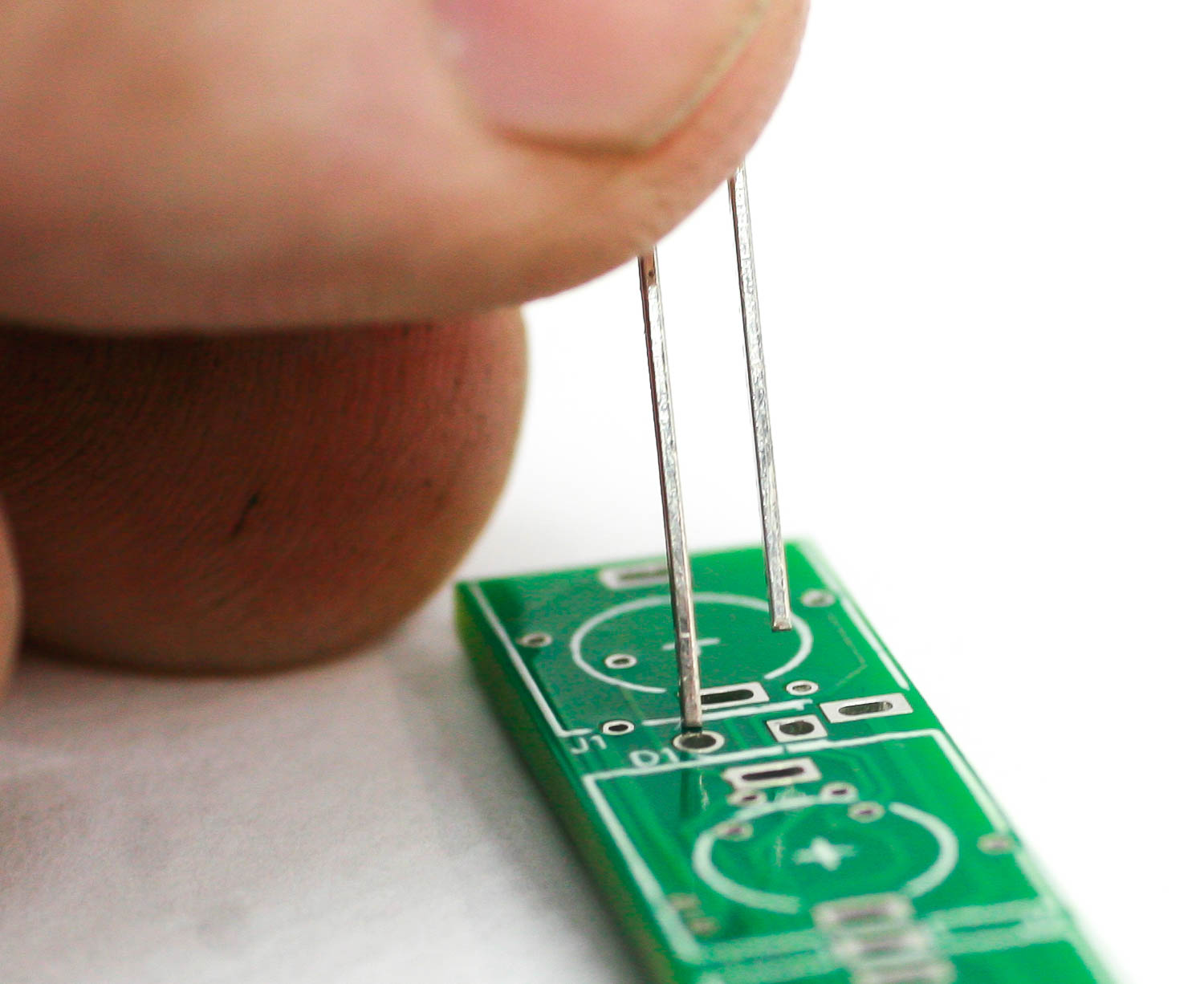
ELECTROLYTIC CAPACITORS
Place the electrolytic caps into the project by placing the longer lead into the square pad, which has the “+” next to it on the PCB silkscreen. Solder in place and trim excess leads very close to the board. Do this VERY CAREFULLY as to not scratch or damage the PCB.
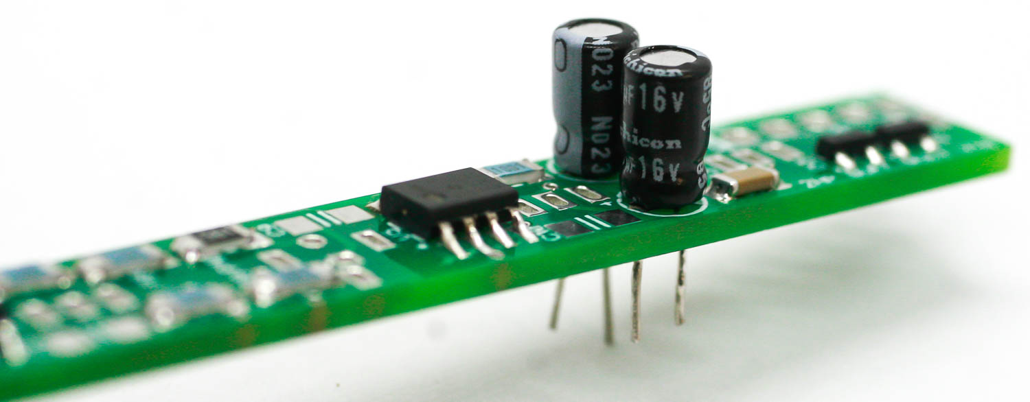
BM – Electrolytic Caps
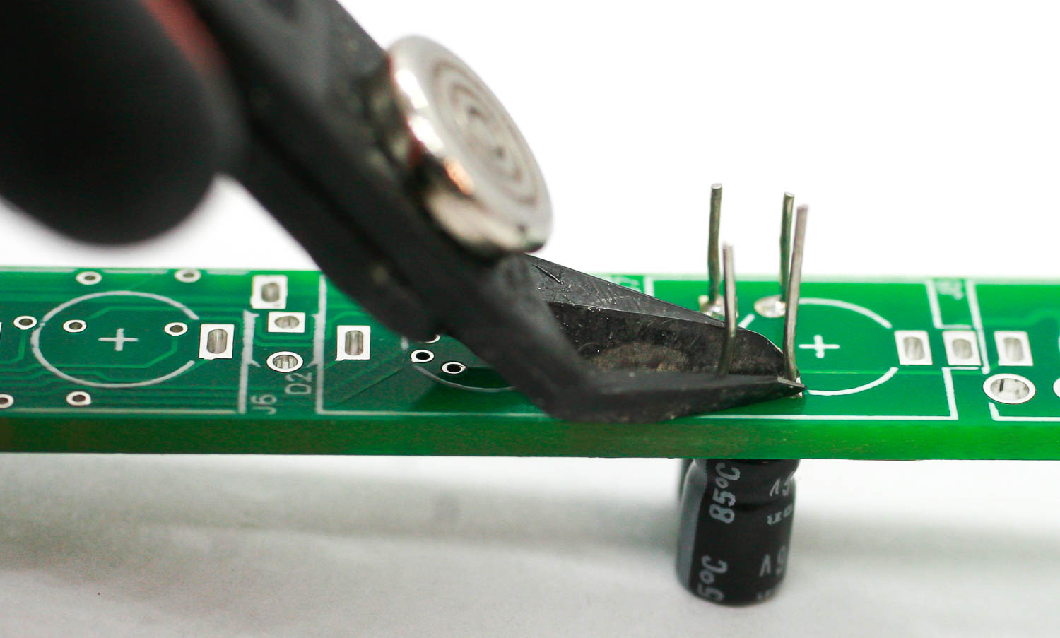
BM- Trim Cap Leads
BM – CAP LEAD TRIMMING
POWER HEADER
Place the single row power connector as shown below. Tack one pin on the backside first with solder and make sure it is perpendicular to the PCB before soldering the remaining pins. Trim the pins very close to the board carefully!
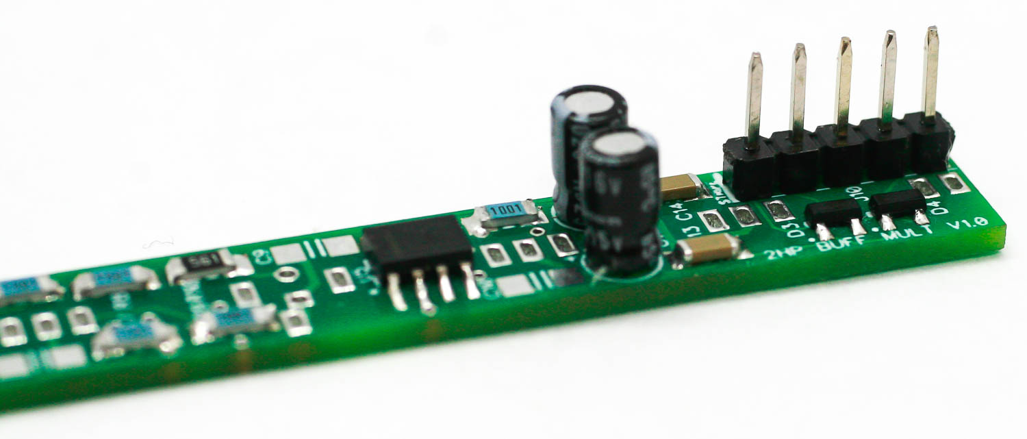
BM – Single Row Power Header
BM – Close Lead Trimming
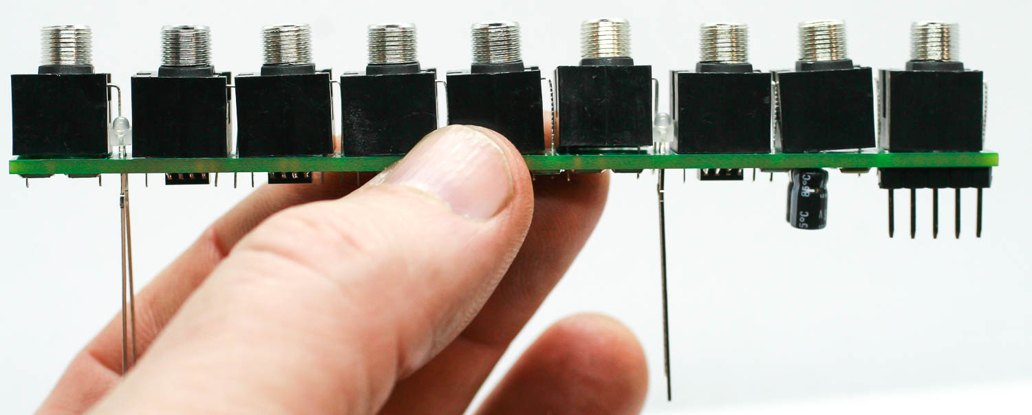
LEDs
Place the LEDs into the pads by placing the longer lead into the circular pad as shown below. DO NOT SOLDER JUST YET!
BM – LED Population
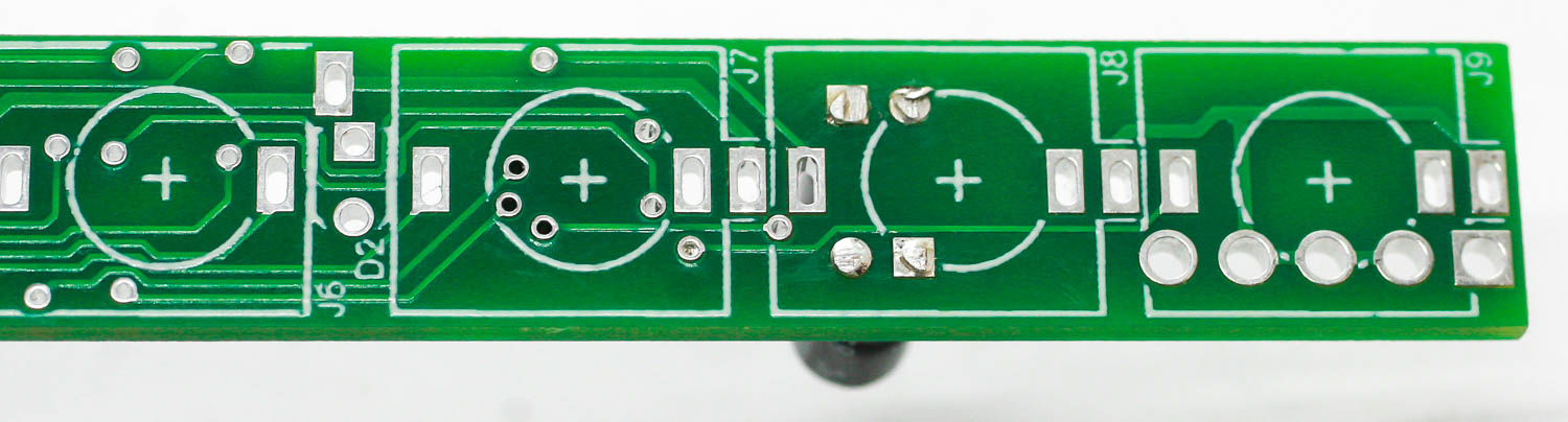
JACKS
Place all the jacks into the PCB and bend over the ground lead on the two jacks nearest to the LEDs as shown below. DO NOT SOLDER THE JACKS JUST YET!
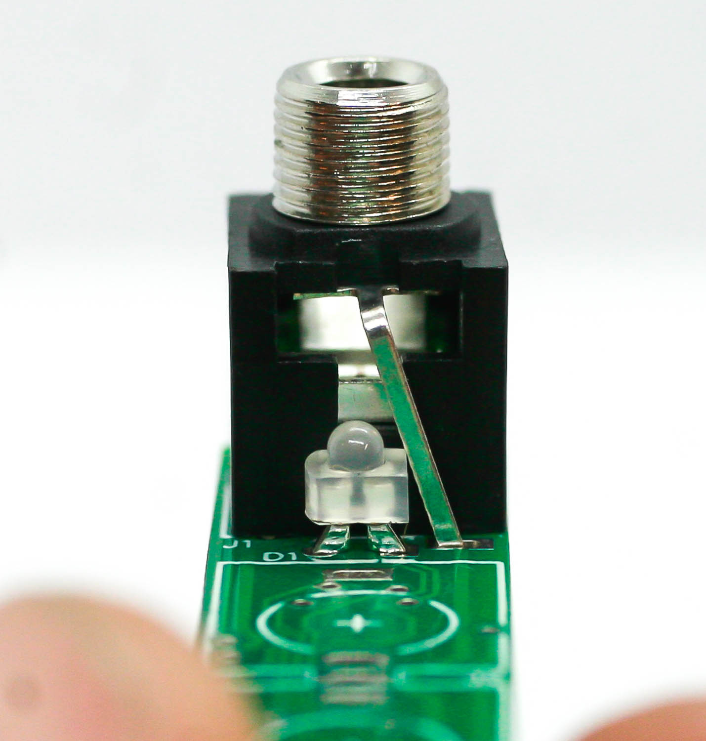
BM – Jack Placement
BM JACKS
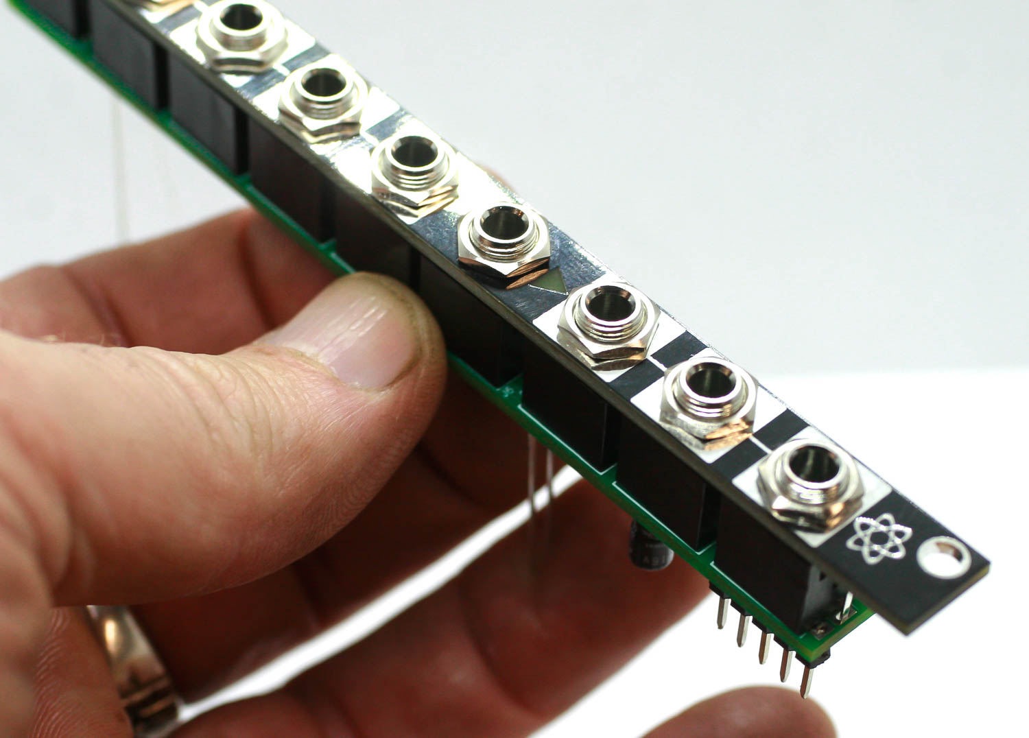
PANEL PLACEMENT
Take the panel and place it over the UNSOLDERED JACKS AND LEDS and finger-tighten the jack nuts onto each jack.
BM – Panel Placement
Press the LEDs up to the panel. then you can solder all the jacks and LEDs in place. Do this carefully and use just a little solder.
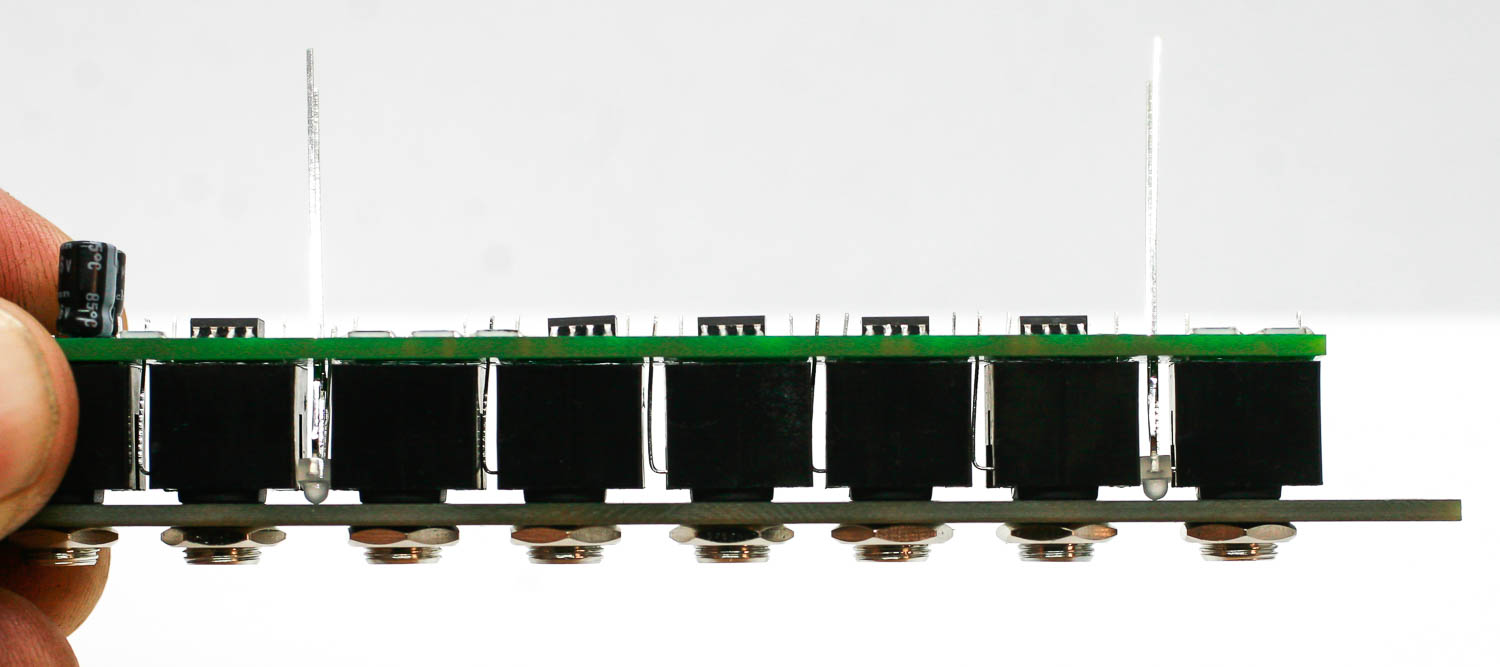
BM – LEDs
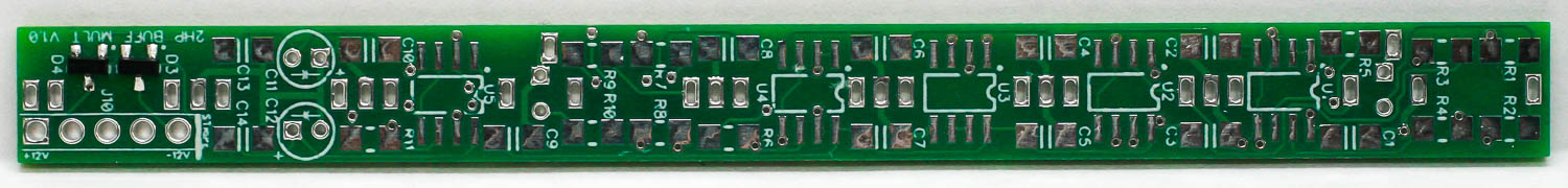
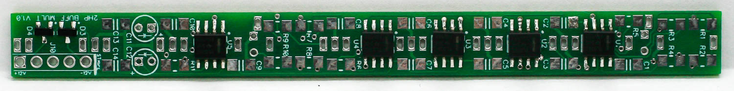
FINAL PROJECT
Once these items are soldered, you are ready to test your module. Make sure you plug your power cable in the correct way!!!
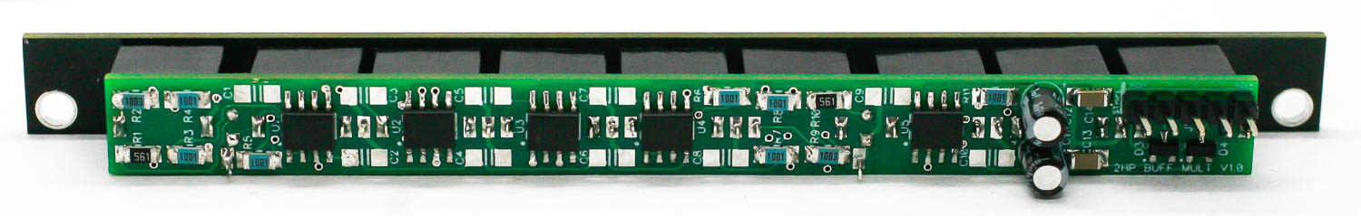
BM – Final Build 1
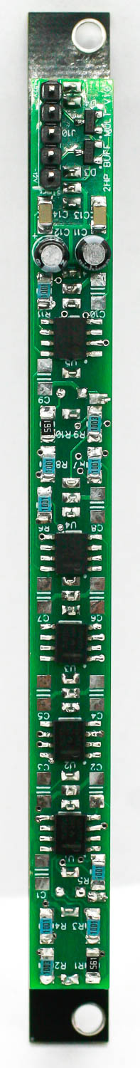
BM – Final Build 2