Important Links
Head Out Assembly Instructions
Thank you for purchasing the Synthrotek Head Out – Eurorack headphone amplifier and line level output module. This is an intermediate build. If you feel like you can handle it, please proceed! If not, get some help from a friend with experience or purchase a fully completed unit.
Please build according to the BOM, and not these instructions or the pictures alone. Some components may have changed since these were written, or we may not be able to get the exact components in the pictures.
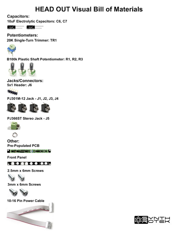
For a bill of materials with part numbers, click here.
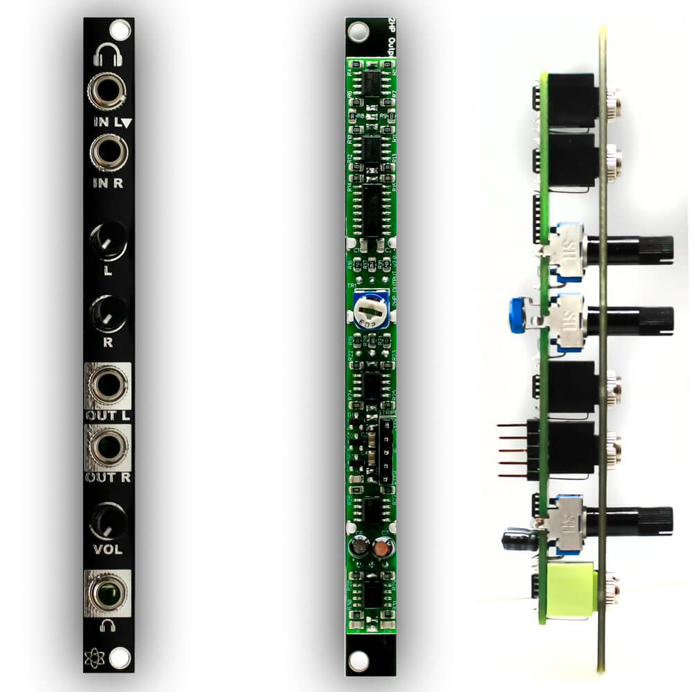
Head Out 2Hp Line Level and Headphone Output
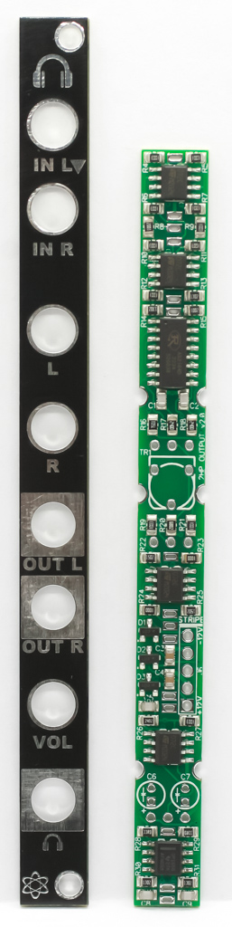
Head Out is a mostly surface mount build, so this is a “finish it yourself” kit.
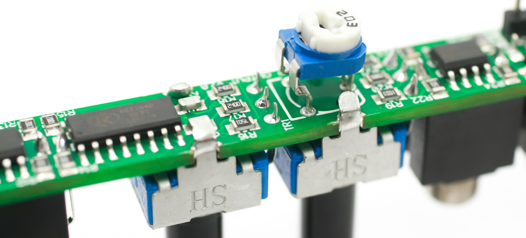
Trimmer Resistor
Place the trimmer resistor into the PCB as shown below, then carefully turn over and solder in place.
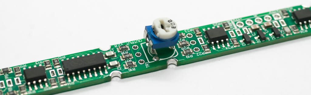
Head Out Trimmer Potentiometer
ELECTROLYTIC CAPACITORS
Place the three electrolytic caps into their respective places. Align them by placing the longer leads through the hole that has the “+” near it. Carefully turnover to solder in place then trim excess leads.
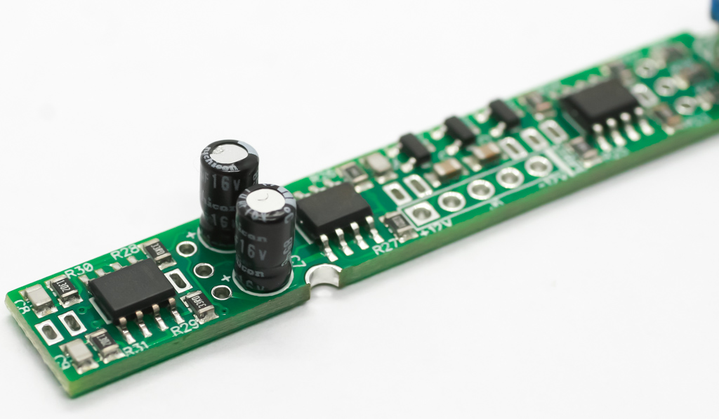
Head Out – Electrolytic Capacitors
Power Header Pins
Place the power header pins into the PCB as shown below. Carefully turn over to solder in place. Please make sure that they are standing straight.
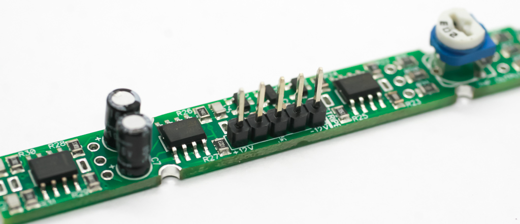
Head Out – Header Pins
After soldering, clip the excess leads (very closely without scratching the PCB or traces!), then touch up the clipped lead ends with a tad more solder.
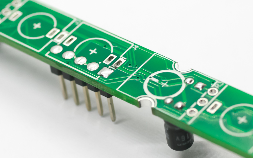
Head Out – Header Pins 2
Jacks
Carefully place the jacks into the PCB as shown below. There is only one green stereo jack, place it as shown below.
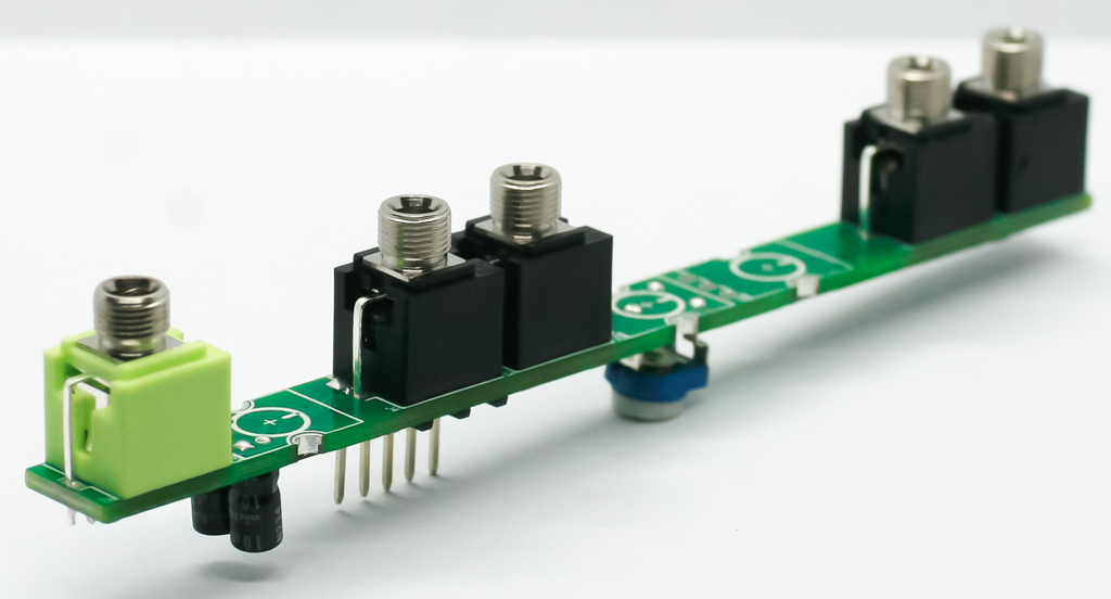
Head Out – Jacks
Before soldering, temporarily place the panel on with the jack nuts only finger-tight. This will allow you to carefully turn the project over and solder the jacks in place.
Head Out jacks 2
Potentiometers
Align and place the pots as shown below. Tuck in the clips a bit and solder those in along with the pins.
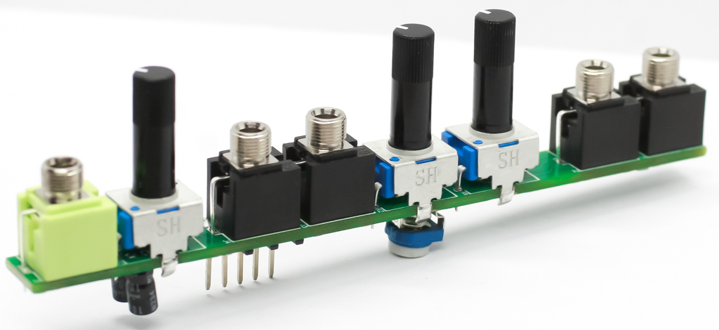
Head Out – Potentiometers
Head Out – Potentiometers 2
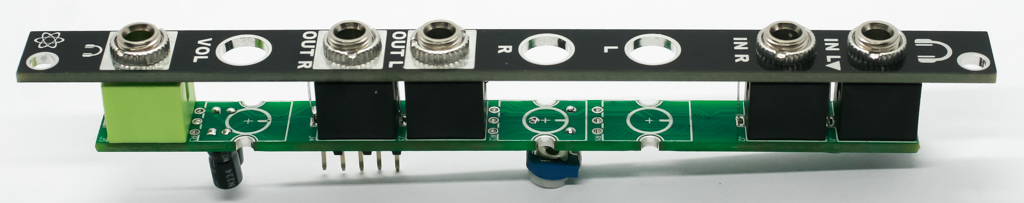
Ok! Once you are done with that, place the panel back on and tighten down the jack nuts (not too tight!) and you are ready to test the module. Make sure to pay attention to the power cable polarity!
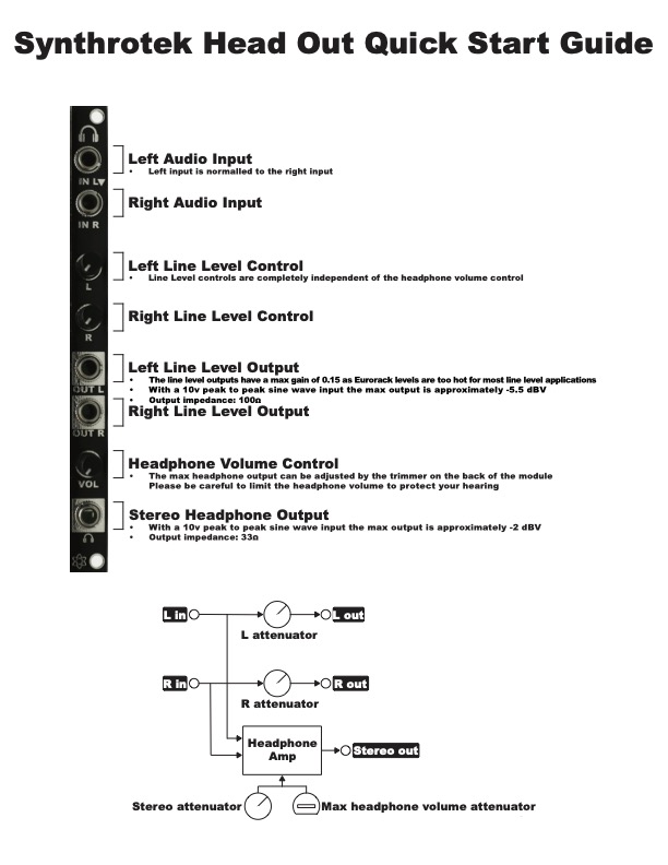
The trimmer on the back of the module attenuates the headphone volume. It does not need to be calibrated.