


Important Links
Product Page
Store Page
Assembly Instructions
Bill of Materials
Quick Start Guide
Manual
Capacitor and Resistor Lookup Guide
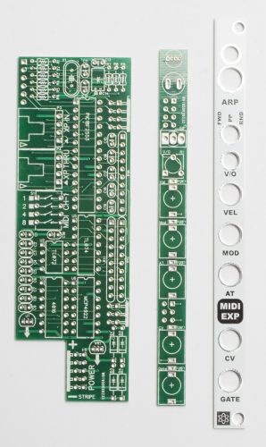
MST MIDI to CV Expander
Thank you for purchasing the MST Midi to CV Expander Eurorack module kit! This is an advanced build. It is very important to get all components flush to the board. If you feel like you can handle it, please proceed! If not, get some help from a friend with experience or purchase a fully completed unit.
ATTN: Please follow the BOM and these instructions and don’t populate from the PCB or these instruction pictures alone. Also sometimes we cannot get the exact pictured components, so please look over your parts and check the codes first.
Lets begin!
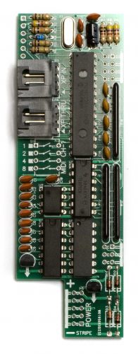
Logic Board
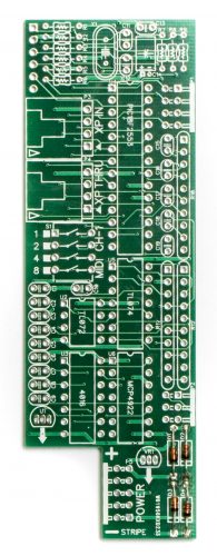
We are going to start with the logic board first, it is the largest of the three boards.
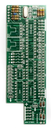
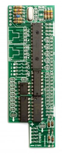
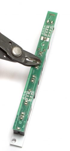
Diodes
First up are the diodes on the logic board. Diodes are polarized, so be careful to align the cathode stripe on the diode with the same cathode strip on the silkscreen. When all four are in place, you can flip the project over onto a hard flat surface, and solder them in place. Then clip the excess part of the leads.
Resistors
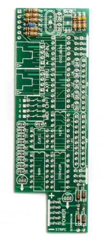
Next up are the resistors. These are not polarized so it doesn’t matter which way they are placed in, but it makes troubleshooting a lot easier if you line up all of the tolerance bands (Usually a gold stripe) on the same side. Insert each resistor, matching the value to the proper spot as per the BOM. In order to get the resistors to fully seat in the PCB, you will need to fold the leads over as close to the body as possible.
Once they are all in there, carefully flip your project over and solder the resistors in place. Then clip any excess leads.
20MHz Crystal
Now we can populate the 20MHz crystal. It isn’t polarized so it can be inserted in the board either direction. Once you have it as close to the board as possible, flip the board over, solder and clip your excess leads.
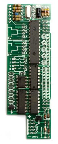
Integrated Circuits
ATTENTION: The ICs are soldered directly to the board on this project to save space. PLEASE ensure all ICs are in their correct spots and facing the right way BEFORE soldering!!
Up next are the ICs, which on this project could be a little tricky. Be very careful inserting these into the board, because the legs can get bent very easily. Also, with them being soldered directly to the board, double check everything before soldering. Trying to do re-work on one of these after the IC is soldered in is almost impossible.
Once you are done, you can flip the project over and solder everything into place. TIP: to get the ICs nice and flat, only solder one or two pins (on opposite corners) on each IC first, then go back and re-heat the solder while applying light pressure to the top of the IC. This will seat the IC firmly against the PCB and ensure it sits flat.
Electrolytic Capacitor & Voltage Regulators
Up next are the electrolytic capacitors and the voltage regulators. When populating the two voltage regulators, make sure to match up the flat side of each regulator with the flat side of the silkscreen (they also have the arrows pointing away from them).
The electrolytic capacitor is also polarized, so make sure when populating it that the side with the stripe goes into the spot that has the ‘-‘ symbol on it.
Once you have everything in place, go ahead and flip the project over and solder everything into place. Clip the excess leads.
Ceramic Capacitors
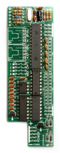
Up next are the ceramic capacitors. These aren’t polarized, and can be inserted into the PCB in any direction. If you purchased a kit from us, the 51pF capacitors will need their legs to be bent in slightly to fit. Once you get them all in there, go ahead and flip the project over, solder the legs, and clip any excess leads. An easy way to get these guys nice and flat is to only solder one leg of the capacitor first, then re-align it while reheating the solder pad.
Resistor Arrays
Resistor arrays are similar to regular resistors, but instead of just one, they have many of the same type of resistor inside of one package to save space. The other difference is that most of the time, they are polarized, meaning you can only put them in one way. When inserting these into the board, line up the dot on the resistor array with the square shaped solder pad. Once all three are in, carefully flip the project over and solder them into place. You can use the same trick as with the ICs on these guys to get them flat and straight. Solder one leg first, reheat and sit flat, then solder the remaining leads.
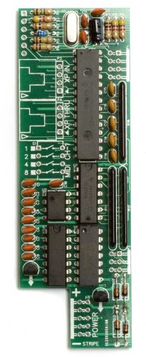
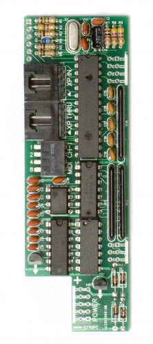
I2C Sockets
Next up are the I2C sockets. These let the Midi to CV Expander talk with the Midi to CV Converter, and also other Midi to CV Expander modules. Populate them in their proper spots as per the BOM, then flip the project over and solder them into place. If you are having trouble keeping them in while flipping the project over, you can use another PCB or a flat, stiff card to help.
SPST DIP Switch
The DIP switch is four SPST switches inside one housing, and lets you select what channel the module will listen for MIDI data on. Insert it into place, then flip the project over and solder it into place.
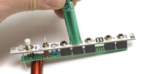
Right Angle Headers & Power Header
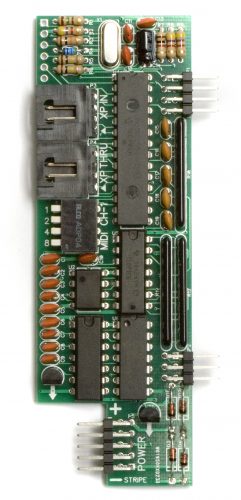
Next up are the 10 pin power header and the two board to board connectors. For the power header, insert it as shown above and then solder one leg. Once you get it flat and parallel with the PCB using the IC trick from earlier, solder the rest of the pins.
For the 4×2 and 3×2 headers, populate them according to the BOM, and then get them flat with the same trick as earlier, but only solder one leg for now, DON’T solder the rest of the legs yet. We want to attach the front panel to this one before we solder everything up.
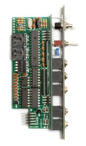
Control Board
Now we are going to get started on the control board. To make things go a little quicker, you can prep your parts by taking the nuts off of your spdt switch, jacks and push button switch.
Trimmer Potentiometer
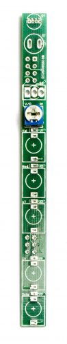
Insert the trimmer into its spot, and then flip the project over and solder it into place.
Jacks, Switches & LED
Next up are the rest of the control board components. Insert each part into its proper spot as per the BOM, and then place the front panel over top, as shown below. Do not solder anything yet!
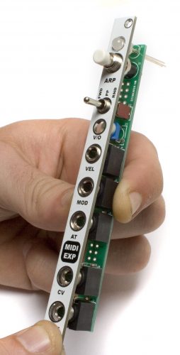
Next, place all of the nuts back on their components and hand tighten them. Once you’ve done that, make sure that the front panel and the PCB are parallel and all the jacks are sitting flat against the PCB.
Now you can use a tool to tighten the nuts down. Be careful not to over-tighten the nuts! The jacks may have shifted slightly during installation or while tightening the nuts down, so it’s recommended to double check real quick that they are sitting flat and that they are nice and straight with the PCB, as there is very little clearance between the side of the front panel and the jacks.
Now carefully flip the project over and solder everything into place. Once you have done that, clip all the leads on the back. You want to get everything as close to the PCB as possible without damaging anything. See the picture below for reference.
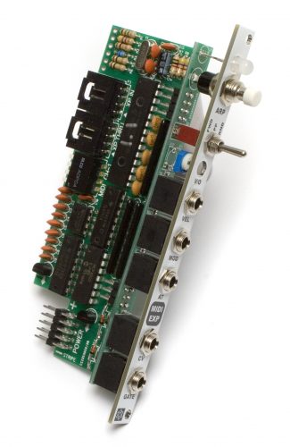
Final Assembly
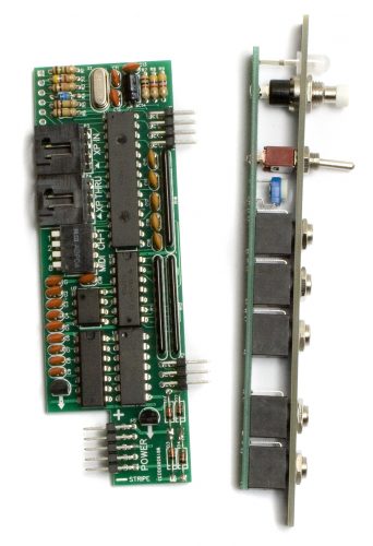
Now we are ready for the final board assembly. It is important to align the two boards so that there almost no space between the two boards. Insert the control panel assembly onto the headers that are on the logic board.
Once you are satisfied with the placement, solder just one pin of each header on the control board and then check the alignment. If something looks off, just reheat that side and re-align it. Once everything is together and straight, solder all the remaining pins on the control and logic board. Clipping the excess leads on the headers after soldering the boards together is optional, but will make it look a little better.
Finished Module
Testing and Calibration
You finished your build! Follow the steps in this guide to check that everything is functioning properly.
Power
Turn off your Eurorack system. Connect your power cable to your module, making sure that it is oriented correctly. Turn your module so that the panel is facing toward you. Power on your Eurorack system. If you hear any loud “pops” or smell anything burning, shut off your power immediately and go straight to the Troubleshooting Guide. If not, proceed to the next section.
Proper I2C cable connection
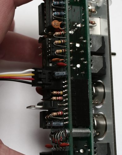
When attaching the I2C cable to the MIDI to CV Converter, ensure that the black wire is facing down, as shown above. If your module came with a shrouded header, there will be only one way it can plug in. In the case that you got an unshrouded header (very first modules), the plug will still fit, but you must be careful while attaching the cable.
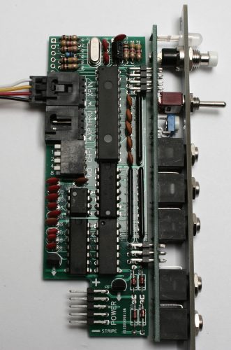
On the other end, insert the I2C cable as shown above, with the black wire facing down again. IMPORTANT: Make sure you plug the I2C cable into the top most socket. It is labeled XP IN on the PCB. The other socket is labeled XP THRU and is for connecting additional expander modules.
Select the channel you want to use the Midi to CV Expander on for testing. We recommend using channel 1 (all switches off) for simplicity during testing and calibration.
Testing the Jacks
- First up, we are going to make sure all the jacks are functioning properly. You can do this by sending midi data into the MIDI to CV Converter. If the expander is receiving data, the LED should flash on each note. While playing a note (either with a keyboard going into the DIN MIDI jack, or using a DAW through the USB jack) plug a patch cable into the CV jack of the Expander, and then plug it into an oscillator. We recommend using an oscillator with a v/o input for testing. While switching notes on your MIDI device, make sure the pitch of the VCO is changing along.
- Take the patch cable and move it from the CV jack to the Gate jack, and hit a few notes on your MIDI device. You should hear the VCOs sound turn into a high pitched sound while you hold the key down.
- Move the patch cable from the gate to the AT (After Touch) jack. Send an after touch signal from your MIDI device, and you should hear the pitch of the VCO rise as more aftertouch is applied.
- Move the patch cable to the MOD jack. Send a modulation signal from your MIDI device, and you should hear the pitch change in accordance with the level of the modulation.
- Move the patch cable to the VEL (velocity) jack. If you send a velocity signal from your MIDI device, you should hear the pitch get higher with a ‘higher’ velocity.
High Note, Low Note, Last Note.
- To cycle between the different modes of the Expander, hold down the reset button until the LED flashes. The color it flashes shows what mode it is in. If it flashes red, its in high note priority, green means low note priority, and amber is last note priority.
- When in high note priority, you should be able to hold a note, and then play a higher one, and the module should switch to that one, and then when you release just the top one, it should switch back. If you hold one note, and play a lower pitched one, the lower pitched one is ignored by the module.
- Low note priority is very similar to high note, but it works the opposite, giving the lower note the priority.
- Last note priority means that the module outputs the last note you played, regardless of what pitch it is.
Arpeggiator Mode
- If you give a short single press to the push button switch, the LED should flash blue, which means the module is now in ARP (arpeggiator) mode. To use this mode, the MIDI to CV Converter needs to be receiving a clock signal.
- With a clock signal going in the MIDI to CV Converter, patch the CV jack of the Expander to your oscillator. Now if you send multiple notes from your MIDI device, the Expander module will switch between them in time with the incoming clock signal.
- The three position switch below the push button dictates what mode the arpeggiator is in, FWD means it will play lowest note to highest note, and then go back to the first note. PP means ping pong, where it goes from lowest to highest, then back down. RND is random, it just bounces around all the notes that are being sent.
- To activate/deactivate “order played” mode, hold the button down and flip the switch to any new position within 2 seconds. The LED will light green when “order played” mode is activated or red when deactivated.
Calibration Instructions
These calibration instructions will detail how to get the Expander to put out 1v per octave CV signals. The instructions will assume the use of a MIDI keyboard, but if using a DAW, just send the appropriate notes out through the MIDI channel. In order to calibrate the Expander, you will need the following items:
- A device capable of sending MIDI data (we recommend a simple MIDI keyboard)
- Small flat head screwdriver (non conductive would be best)
- Volt meter
- Patch cables
- Start by plugging your MIDI device into the MIDI to CV Converter. Insert one end of a patch cable into the CV output of the Expander. To measure voltage, you can either use alligator clips on the patch cable, or have a friend hold them. Using one of these methods, attach the red lead from your volt meter to the tip of the patch cable, and attach the sleeve of the patch cable to the black lead of your volt meter. Make sure your volt meter is set to read DC voltage.
- Play C1 on your MIDI device. The output on the voltmeter should read 0v (or really close to it).
- Now play C3 on your MIDI device, and check the output of the volt meter. It should be close to 2v. If it is low, turn the trim pot on the front of the module to the right to raise the voltage until it is within 0.005v. If the voltage is high, turn the trim pot to the left to lower it.
- Next, play C5 on your MIDI device, and check the output of the volt meter. It should be almost dead on 4v. If off by more than 0.005v or so, adjust the trim pot so that it is close.
- Finally, play C7 on your MIDI device, and check the output of the volt meter. If the last two steps went well, it should be at 6v. If not, adjust like before, and then repeat these steps to ensure that it is still in tune.
That’s it! If you’re kit isn’t working quite right, head on over to the Troubleshooting Guide. Nine times out of ten, following the steps there will fix it. If that doesn’t solve it, email us at store@synthrotek.com for help.
If we can’t fix it over email, you can mail in your kit to us for a FREE 30-minute diagnostic. If we can’t fix it in 30 minutes, we will contact you with an update and an cost estimate before doing any more work. We will bill you for any parts and the shipping back.
Thanks for DIYing with Synthrotek!